Sign In
Upload
Download
Table of Contents
Contents
Add to my manuals
Delete from my manuals
Share
URL of this page:
HTML Link:
Bookmark this page
Add
Manual will be automatically added to "My Manuals"
Print this page
×
Bookmark added
×
Added to my manuals
Manuals
Brands
hilscher Manuals
Gateway
netFIELD
User manual
hilscher netFIELD User Manual
Hide thumbs
1
2
3
4
5
6
7
8
9
10
11
12
13
14
15
16
17
18
19
20
21
22
23
24
25
26
27
28
29
30
31
32
33
34
35
36
37
38
39
40
41
42
43
44
45
46
47
48
49
50
51
52
53
54
55
56
57
58
59
60
61
62
63
64
65
66
67
68
69
70
71
72
73
74
75
76
77
78
79
80
81
82
83
84
85
86
87
88
89
90
91
92
93
94
95
96
97
98
99
100
101
102
103
104
105
106
107
108
109
110
111
112
113
114
115
116
117
118
119
120
121
122
123
124
125
126
127
128
129
130
131
132
133
134
135
136
137
138
139
140
141
142
143
144
145
146
147
148
149
150
151
152
153
154
155
156
157
158
159
160
161
162
163
164
165
166
page
of
166
Go
/
166
Contents
Table of Contents
Bookmarks
Table of Contents
Table of Contents
1 About this Document
Description of the Contents
List of Revisions
Table 1: List of Revisions
Conventions in this Document
2 Brief Description
3 Safety
Intended Use
General Note
Personnel Qualification
Modification Reserved
Safety Instructions to Avoid Personal Injury
Safety Instructions to Avoid Device Damage
Labeling of Safety Messages
Table 2: Signal Words in Safety Messages on Personal Injury
Table 3: Safety Signs in Messages on Personal Injury
Table 4: Signal Words in Safety Messages on Property Damage
Table 5: Safety Signs in Safety Messages on Property Damage
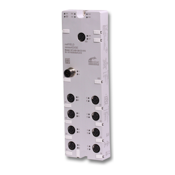
4 Hardware Description
Device Overview
Figure 1: Device Overview with Interfaces
Table 6: Positions on Sensoredge
Interfaces
Supply Voltage
Table 7: Supply Voltage
Ethernet Connector
Table 8: Ethernet
IO-Link Master
Table 9: IO-Link (Class A)
Leds
SYS (System) LED
CLD (Cloud) LED
Table 10: SYS (System) LED
Table 11: CLD (Cloud) LED
EDG (Edge) LED
Power Supply Leds
Table 12: EDG (Edge) LED
Table 13: 1L and 2L Leds
Ethernet Leds
IO-Link Port Status Leds
Table 14: Ethernet Leds
Table 15: IO-Link Port Status Leds
Block Diagram
Figure 2: Sensoredge Block Diagram
5 Commissioning and First Steps
Overview
Quick Commissioning
Table 16: Quick Commissioning of the Sensoredge Device
Advanced Setup
Table 17: Advanced Setup Sensoredge
Installation
Before You Begin
Mounting
Power Supply Requirements
Connecting Cables
After Installation
Create User Account in Sensoredge Portal
Figure 3: Create a New Account Dialog
Figure 4: Account Information
Pair Sensoredge Device with Your Sensoredge Account ("Onboarding")
Figure 5: Sensoredge Portal Landing Page
Figure 6: Empty Device Manager in Sensoredge Portal
Figure 7: Onboarding Page in Sensoredge Portal
Figure 8: Device Overview in Device Manager
Figure 9: Device Details in Device Manager
Create Dashboard(S) and Monitor IO-Link Sensor Data
Figure 10: Sensoredge Portal Landing Page
Figure 11: Dashboard Manager Start Page
Figure 12: New Dashboard Dialog
Figure 13: Empty New Dashboard
Figure 14: Drag and Drop Widget
Figure 15: Edit Chart
Figure 16: Empty Data Source Tab
Figure 17: Data Source Tab
Figure 18: Line Chart Preview
Figure 19: Change Sensor Name
Figure 20: Visualization Panel
Figure 21: Defining Line Color of Sensor Data
Table 18: Panel Configuration (Line Chart Visualization Parameters)
Figure 22: Sensor Meta Data Tab
Figure 23: Sensor Health Data Tab
Figure 24: Configured Line Chart Widget
Advanced Configuration
Login to Local Device Manager for Advanced Configuration
Figure 25: Login Device Manager
Figure 26: Enter Current Password Dialog
Figure 27: Enter New Password Dialog
Figure 28: Re-Authentication Dialog
Adjust System Time (Optional)
Figure 29: System Time Value
Figure 30: Change System Time Dialog
IO-Link Configuration (Optional)
Figure 31: Missing IODD in Live View
Figure 32: Attachments Page
Figure 33: Attachments Add Dialog
Figure 34: File Selection Dialog
Figure 35: Selected File in Add Device Attachments Dialog
6 Querying Sensoredge Data Via Netfield Cloud Websocket API Services
Overview
Figure 36: Topics on Device's Details Page
Monitor Data with Node-RED
Figure 37: Manage Palette
Figure 38: Install Netfield Websocket Nodes
Figure 39: Netfield Websocket Node
Figure 40: Editing Netfield Websocket Node
Figure 41: Properties of Netfield Websocket Node
Figure 42: Copy API Key in Sensoredge Portal
Figure 43: Paste API Key in Node-RED
Figure 44: Copy Device ID in Sensoredge Portal
Figure 45: Paste Device ID in Node-RED
Figure 46: Copy Data Topic in Sensoredge Portal
Figure 47: Paste Topic in Node-RED
Figure 48: Add and Connect Payload Node
Figure 49: Rename Telemetry Debug Node
Figure 50: Display Payload Data
Figure 51: Add Health Node
Figure 52: Properties of Health Websocket Node
Figure 53: Copy Health Topic String in Portal
Figure 54: Authorization Tab
Figure 55: Health Flow Added
Figure 56: Rename Debug Node
Figure 57: Debug Tab
Figure 58: Selected Nodes Filter
Figure 59: Health Payload Data in Debug Tab
Structure of JSON Messages
Data Message
Table 19: Important Elements in Data Message
Health Message
Table 20: Important Elements in Health Message
Code Examples for Querying Data Via Websocket
7 Local Device Manager
Overview
Figure 60: Overview Device Manager
System
Figure 61: System Page
Figure 62: Change Host Name Dialog
Networking
Overview
Figure 63: Networking Page
Figure 64: Details of LAN Interface (Eth0)
Figure 65: Ipv4 Settings
Figure 66: Manual Ipv4 Settings
Network Proxy Settings
Figure 67: Network Proxy Configuration
Figure 68: Proxy Settings Dialog Window
Figure 69: Using One Proxy Server for All Protocols
Figure 70: Separate HTTP/HTTPS/FTP Configuration
Figure 71: Restart Dialog after Changing Proxy Server Configuration
Accounts
Figure 72: Accounts
Figure 73: Create New Account
Figure 74: Edit Account
Certificate
Figure 75: Web Server Certificate
System Update
Operating System
Figure 76: os Update Page
Figure 77: Selected os Update Image
Figure 78: Upload Finished Message
Figure 79: os Update "Disconnected" Message
Netx 90 Firmware
Figure 80: Netx 90 Firmware Update Page
Logs
Figure 81: Logs
IO-Link Configurator
Overview
Figure 82: Overview of IO-Link Configurator
IO-Link Configurator Dashboard
Figure 83: Live View Tab in Dashboard
Figure 84: Payload Tab in Dashboard
Table 21: Elements in Payload Tab
Figure 85: Container Info Tab in Dashboard
Connected Device
Figure 86: Info Tab of Sensoredge IO-Link Master
Figure 87: Info Tab of Port
Table 22: Elements in Port Info Tab
Figure 88: Example of Master Event Message
Figure 89: Example of Device Event Message
Figure 90: Configuration Tab of Port
Table 23: Elements in Configuration Tab of Port
Figure 91: Tabs of Connected Sensor (Example)
Figure 92: Missing IODD File Message
Attachments
Figure 93: Attachments Page
Figure 94: Add Device Attachments Dialog
Table 24: Elements on Attachments Page
Figure 95: Upload IODD
Figure 96: Selected File in Add Device Attachments Dialog
Figure 97: Delete Dialog
Figure 98: Attachments Memory
8 Sensoredge Portal
Sign In, Landing Page & Account Menu (User Profile)
Figure 99: Sign in Dialog
Figure 100: Landing Page Sensoredge Portal
Figure 101: User Profile
Table 25: User Profile Parameters
Figure 102: Sensoredge Documentation Page
Device Manager
Start Page
Figure 103: Sensoredge Portal Device Manager Start Page
Table 26: Elements on Device Manager Start Page
Device Details Page
Figure 104: Device Details Page
Table 27: Elements on Device Details Page
Onboarding Page
Figure 105: Device Manager Onboarding Dialog
Table 28: Elements on Onboarding Page
Dashboard Manager
Brief Description
Start Page
Figure 106: Start Page
Table 29: Elements on Dashboard Manager Start Page
Dashboard
Figure 107: Dashboards
Table 30: Elements in Dashboard
Figure 108: Resizing Widget Window
Line Chart Widget
Figure 109: Line Chart Live
Figure 110: Drag Chart
Figure 111: Line Chart Configuration Window
Figure 112: Line Chart Data Source Panel
Table 31: Elements in Data Source Panel
Figure 113: Line Chart Visualization Panel
Table 32: Panel Configuration (Line Chart Visualization Parameters)
Figure 114: Sensor Visualization Parameters
Gauge Chart Widget
Figure 115: Live Gauge
Figure 116: Drag Gauge Widget
Figure 117: Gauge Chart Configuration Window
Figure 118: Gauge Data Source Panel
Figure 119: Gauge Chart Visualization Panel
Table 33: Elements in Data Source Panel
Table 34: Panel Configuration (Gauge Chart Visualization Parameters)
Vertical Bar Chart Widget
Figure 120: Vertical Bar Chart Live
Figure 121: Drag Bar Chart
Figure 122: Vertical Bar Chart Configuration Window
Figure 123: Vertical Bar Chart Data Source Panel
Table 35: Elements in Data Source Panel
Figure 124: Vertical Bar Chart Visualization Panel
Figure 125: Sensor Visualization Parameters
Table 36: Panel Configuration (Vertical Bar Chart Visualization Parameters)
API Key Manager
Figure 126: API Key Manager Start Page
Figure 127: API Key Details Page
Table 37: Elements on API Key Manager Start Page
Figure 128: Add API Key Dialog
Table 38: Elements on API Key Details Page
9 Device Recovery
10 Technical Data
Table 39: Technical Data Sensoredge
Table 40: Technical Data IO-Link Ports
11 Decommissioning, Dismounting and Disposal
12 Appendix
12.1 IO-Link Event Codes
IO-Link Master Event Codes
IO-Link Device Event Codes (Common)
List of Figures
Advertisement
Quick Links
Download this manual
User manual
netFIELD sensorEDGE
Hilscher Gesellschaft für Systemautomation mbH
www.hilscher.com
DOC200601UM01EN | Revision 1 | English | 2021-09 | Released | Public
Table of
Contents
Previous
Page
Next
Page
1
2
3
4
5
Advertisement
Chapters
Table of Contents
2
List of Figures
160
Table of Contents
Need help?
Do you have a question about the netFIELD and is the answer not in the manual?
Ask a question
Questions and answers
Related Manuals for hilscher netFIELD
Gateway hilscher NOIT-E-NPI3-51-EN-RE User Manual
Netpi edge gateway (57 pages)
Gateway hilscher netPI NOIT-E-NPI3-51-EN-RE User Manual
(65 pages)
Gateway hilscher NIOT-E-TIB100-GB-RE User Manual
Edge gateway (145 pages)
Gateway hilscher NIOT-E-TIB100-GB-RE User Manual
Netiot edge gateway (263 pages)
Gateway hilscher NIOT-E-TPI51-EN-RE User Manual
Netiot edge gateway (294 pages)
Gateway hilscher NIOT-E-TPI51-EN-RE User Manual
Netiot edge gateway (258 pages)
Gateway hilscher NIOT-E-TIJCX-GB-RE User Manual
Netiot edge gateway v1.2.0.0 (292 pages)
Gateway hilscher netNode Hardware Description Installation Instructions
(28 pages)
Gateway hilscher netTAP NT 50 Series User Manual
Gateway devices (86 pages)
Gateway hilscher netTAP NT 50 User Manual
Gateway devices (92 pages)
Gateway hilscher netFIELD NIOT-ETPI51-EN-RE/NFLD User Manual
(91 pages)
Gateway hilscher netFIELD Compact X8M User Manual
(136 pages)
Gateway hilscher netBRICK NB 100 User Manual
(135 pages)
Gateway hilscher EU5C-SWD-POWERLINK SmartWire-DT User Manual
Smartwire-dt gateway (72 pages)
Gateway hilscher EU5C-SWD-ETHERCAT User Manual
Smartwire-dt gateway (98 pages)
Gateway hilscher netTAP NT 151-RE-RE User Manual
Real-time ethernet gateway (81 pages)
This manual is also suitable for:
Sensoredge
Table of Contents
Print
Rename the bookmark
Delete bookmark?
Delete from my manuals?
Login
Sign In
OR
Sign in with Facebook
Sign in with Google
Upload manual
Upload from disk
Upload from URL


Need help?
Do you have a question about the netFIELD and is the answer not in the manual?
Questions and answers