
Related Manuals for hilscher EU5C-SWD-POWERLINK SmartWire-DT


Summary of Contents for hilscher EU5C-SWD-POWERLINK SmartWire-DT
- Page 1 User Manual SmartWire-DT Gateway EU5C-SWD-POWERLINK Hilscher Gesellschaft für Systemautomation mbH www.hilscher.com DOC130802UM02EN | Revision 2 | English | 2013-12 | Released | Public...
-
Page 2: Table Of Contents
Device Description EU5C-SWD-POWERLINK Gateway..........21 3.1.1 Function......................21 3.1.2 Configuration ......................22 3.1.3 Interfaces......................24 3.1.4 Diagnosis......................24 3.1.5 Firmware and Device Description File..............24 Prerequisites for Operation..................25 SmartWire-DT Gateway | EU5C-SWD-POWERLINK DOC130802UM02EN | Revision 2 | English | 2013-12 | Released | Public © Hilscher 2013... -
Page 3: Table Of Contents
10.1 Overview........................62 10.2 IP Address of Gateway .....................62 10.3 Prerequisites......................64 10.4 Step-by-Step Instructions for Updating Firmware .............64 10.5 Resetting Gateway ....................66 SmartWire-DT Gateway | EU5C-SWD-POWERLINK DOC130802UM02EN | Revision 2 | English | 2013-12 | Released | Public © Hilscher 2013... -
Page 4: Table Of Contents
11.2 Technical Data POWERLINK Controlled Node ............69 ANNEX ........................70 12.1 List of Figures ......................70 12.2 List of Tables ......................71 12.3 Contacts........................72 SmartWire-DT Gateway | EU5C-SWD-POWERLINK DOC130802UM02EN | Revision 2 | English | 2013-12 | Released | Public © Hilscher 2013... -
Page 5: Introduction
Please first read the Safety chapter on page 16 ff. 1.1.1 List of Revisions Revision Date Chapter Revisions 2013-10-15 Created 2013-12-09 Section Diagnosis/Status Response revised. Table 1: List of Revisions SmartWire-DT Gateway | EU5C-SWD-POWERLINK DOC130802UM02EN | Revision 2 | English | 2013-12 | Released | Public © Hilscher 2013... -
Page 6: Conventions In This Manual
Results <result> For a description of the labeling of Safety Messages, see Labeling of Safety Messages section on page 20. SmartWire-DT Gateway | EU5C-SWD-POWERLINK DOC130802UM02EN | Revision 2 | English | 2013-12 | Released | Public © Hilscher 2013... -
Page 7: Versions Of Devices, Firmware, Software Tools, Drivers And Device Description File
This manual refers to the following driver versions: Driver File name Version Windows USB Driver usbser.sys Depending on Windows version Table 4: Reference to Drivers SmartWire-DT Gateway | EU5C-SWD-POWERLINK DOC130802UM02EN | Revision 2 | English | 2013-12 | Released | Public © Hilscher 2013... -
Page 8: Software Package
You need the SWD-Assist software in order to configure the EU5C-SWD- POWERLINK gateway. The software can be ordered separately from Hilscher under the product name EU5C-SWD-SW (order number 3233.920). The package contains the SmartWire-DT Gateway Solutions product DVD and a Mini-USB cable. - Page 9 Eaton SWD-Assist software, or you can download SWD-Assist directly from the www.moeller.net website under Support > Download Center. Direct link: http://downloadcenter.moeller.net/en/software.a487d8b7-da91-486f-b3ba-a7ca2035db99 You can download other content stored on the DVD from the Hilscher website under Support > Downloads . www.hilscher.com...
-
Page 10: How To Use The Product Dvd
SWD-Assist software. Ethernet Device Scanner/Configuration Tool: installs the Hilscher Ethernet Device Configuration Tool on your PC. PROFINET GSDML File: opens a link to the device description file of the EU5C-SWD-PROFINET gateway. -
Page 11: Notes On Installing The Usb Driver
XP, choose Start menu > Control Panel > Add or Remove Programs, then select: Windows Driver Package – Hilscher GmbH (hilusbser) Ports entry. Click Change/Remove button to uninstall the driver. Under Windows 7 and 8, choose Start menu > Control Panel > Uninstall a program, then select: Windows Driver Package –... -
Page 12: Documentation Overview
DT\SmartWire-DT - The SmartWire-DT system. System\ MN05006002Z_EN.pdf Operating Instruction Hilscher Ethernet Device DOC050402OIxxEN Documentation\english\ Manual of Hilscher Ethernet Configuration 1.Software\Ethernet Device Configuration Tool. Device Setup Utility\ Ethernet Device Configuration OI xx EN.pdf Online help for SWD-Assist... -
Page 13: Legal Notes
There is no entitlement to revisions of delivered documents. The manual delivered with the product applies. Hilscher Gesellschaft für Systemautomation mbH is not liable under any circumstances for direct, indirect, incidental or follow-on damage or loss of earnings resulting from the use of the information contained in this publication. -
Page 14: Exclusion Of Liability
14/72 1.5.3 Exclusion of Liability The software was produced and tested with utmost care by Hilscher Gesellschaft für Systemautomation mbH and is made available as is. No warranty can be assumed for the performance and flawlessness of the software for all usage conditions and cases and for the results produced when utilized by the user. -
Page 15: Export Regulations
Ethernet POWERLINK and B & R Automation Studio are trademarks of B&R, Bernecker + Rainer Industrie-Elektronik Ges.m.b.H, Eggelsberg, Austria. All other mentioned trademarks are property of their respective legal owners. SmartWire-DT Gateway | EU5C-SWD-POWERLINK DOC130802UM02EN | Revision 2 | English | 2013-12 | Released | Public © Hilscher 2013... -
Page 16: Safety
(IEC 60950-1:2005, modified); German Edition EN 60950-1:2006 [S3] EN 61340-5-1 and EN 61340-5-2 as well as IEC 61340-5-1 and IEC 61340-5-2 SmartWire-DT Gateway | EU5C-SWD-POWERLINK DOC130802UM02EN | Revision 2 | English | 2013-12 | Released | Public © Hilscher 2013... -
Page 17: Safety Instructions To Avoid Personal Injury
(for example, by means of separate limit switches, mechanical interlocks etc.). SmartWire-DT Gateway | EU5C-SWD-POWERLINK DOC130802UM02EN | Revision 2 | English | 2013-12 | Released | Public © Hilscher 2013... -
Page 18: Safety Instructions To Avoid Property Damage
(VDE 0100 Part 410) or HD 384.4.41 S2. The allowed range for the supply voltage is indicated in the Technical Data EU5C-SWD-POWERLINK Gateway section on page 67. SmartWire-DT Gateway | EU5C-SWD-POWERLINK DOC130802UM02EN | Revision 2 | English | 2013-12 | Released | Public © Hilscher 2013... -
Page 19: Electrostatic Sensitive Device
Wear an approved grounding wrist strap. If possible, use a static-safe workstation. When not in use, store the device in appropriate static-safe packaging. SmartWire-DT Gateway | EU5C-SWD-POWERLINK DOC130802UM02EN | Revision 2 | English | 2013-12 | Released | Public © Hilscher 2013... -
Page 20: Labeling Of Safety Messages
Indicates a property damage message. message. Indicates an important note in the Indicates an important note in the manual. Note manual. Table 8: Signal Words SmartWire-DT Gateway | EU5C-SWD-POWERLINK DOC130802UM02EN | Revision 2 | English | 2013-12 | Released | Public © Hilscher 2013... -
Page 21: Descriptions And Requirements
1000 Bytes of process input/output data can in sum be exchanged with up to 99 SmartWire-DT participants (slaves). Figure 1: Data Flow EU5C-SWD-POWERLINK Gateway SmartWire-DT Gateway | EU5C-SWD-POWERLINK DOC130802UM02EN | Revision 2 | English | 2013-12 | Released | Public © Hilscher 2013... -
Page 22: Configuration
PC to the gateway via USB, where it is stored (like the target configuration) zero voltage-safe in the flash memory of the device. SmartWire-DT Gateway | EU5C-SWD-POWERLINK DOC130802UM02EN | Revision 2 | English | 2013-12 | Released | Public © Hilscher 2013... - Page 23 I/O modules (i. e. the SmartWire-DT slaves). Finally, you can load the project onto your POWERLINK Managing Node. SmartWire-DT Gateway | EU5C-SWD-POWERLINK DOC130802UM02EN | Revision 2 | English | 2013-12 | Released | Public © Hilscher 2013...
-
Page 24: Interfaces
Assist software. It can then be imported into a POWERLINK engineering tool (like e. g. Automation Studio by B & R). SmartWire-DT Gateway | EU5C-SWD-POWERLINK DOC130802UM02EN | Revision 2 | English | 2013-12 | Released | Public © Hilscher 2013... -
Page 25: Prerequisites For Operation
SmartWire-DT network and, if necessary, plan for an additional feeder module EU5C-SWD-PF2. You can find information on the power consumption in the operating manuals of the SmartWire-DT devices. SmartWire-DT Gateway | EU5C-SWD-POWERLINK DOC130802UM02EN | Revision 2 | English | 2013-12 | Released | Public © Hilscher 2013... - Page 26 Cable protection for cable AWG 24 in accordance with UL 508 und CSA- 22.2 No. 14: Miniature circuit-breaker 24 V DC rated operational current 2 A; Tripping characteristics Z or Fuse 2 A SmartWire-DT Gateway | EU5C-SWD-POWERLINK DOC130802UM02EN | Revision 2 | English | 2013-12 | Released | Public © Hilscher 2013...
-
Page 27: Device Picture, Connectors And Leds
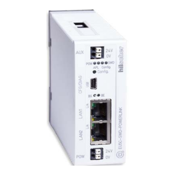
LEDs Gateway functions (see subsequent section for details) 24 V power supply AUX SmartWire-DT connection (plug, 8-pole) Figure 2: Front View EU5C-SWD-POWERLINK Gateway SmartWire-DT Gateway | EU5C-SWD-POWERLINK DOC130802UM02EN | Revision 2 | English | 2013-12 | Released | Public © Hilscher 2013... -
Page 28: Positions And Meaning Of The Leds
L/A: LINK/Activity for channel 0 Receive/Transmit (RX/TX) for channel 0 L/A: LINK/Activity for channel 1 Receive/Transmit (RX/TX) for channel 1 Figure 3: LEDs EU5C-SWD-POWERLINK Gateway SmartWire-DT Gateway | EU5C-SWD-POWERLINK DOC130802UM02EN | Revision 2 | English | 2013-12 | Released | Public © Hilscher 2013... -
Page 29: Descriptions Of The Leds
No communication with the POWERLINK PLC, or the gateway does (off) not have a project configuration. Table 9: Description of the LEDs (1) SmartWire-DT Gateway | EU5C-SWD-POWERLINK DOC130802UM02EN | Revision 2 | English | 2013-12 | Released | Public © Hilscher 2013... - Page 30 LED yellow Ch0 & Ch1 This LED is not used (yellow) Numbers in picture: & Table 10: Description of the LEDs (2) SmartWire-DT Gateway | EU5C-SWD-POWERLINK DOC130802UM02EN | Revision 2 | English | 2013-12 | Released | Public © Hilscher 2013...
-
Page 31: Pinning Powerlink Interface
Bob Smith-Termination TERM Table 11: Ethernet Interface Channel 0 and Channel 1 Pin Assignment (RJ45) Note: The Ethernet interface supports Auto-Crossover. SmartWire-DT Gateway | EU5C-SWD-POWERLINK DOC130802UM02EN | Revision 2 | English | 2013-12 | Released | Public © Hilscher 2013... -
Page 32: Device Type Label
Operating ambient temperature Device type name Part number Hardware revision number Serial number Figure 5:Device Type Label EU5C-SWD-POWERLINK Gateway SmartWire-DT Gateway | EU5C-SWD-POWERLINK DOC130802UM02EN | Revision 2 | English | 2013-12 | Released | Public © Hilscher 2013... -
Page 33: Getting Started
Download POWERLINK configuration to PLC Connect gateway to POWERLINK network Section Connecting POWERLINK on page 41 Table 12: Getting Started SmartWire-DT Gateway | EU5C-SWD-POWERLINK DOC130802UM02EN | Revision 2 | English | 2013-12 | Released | Public © Hilscher 2013... -
Page 34: Installing Gateway
Wear an approved grounding wrist strap. If available, use a static-safe workstation. When not in use, store the device in an appropriate static-safe packaging. SmartWire-DT Gateway | EU5C-SWD-POWERLINK DOC130802UM02EN | Revision 2 | English | 2013-12 | Released | Public © Hilscher 2013... -
Page 35: Mounting Gateway
Figure 7: Hook Gateway to Upper Railing SmartWire-DT Gateway | EU5C-SWD-POWERLINK DOC130802UM02EN | Revision 2 | English | 2013-12 | Released | Public © Hilscher 2013... - Page 36 Figure 9: Gateway is Clamped to Top Hat Rail SmartWire-DT Gateway | EU5C-SWD-POWERLINK DOC130802UM02EN | Revision 2 | English | 2013-12 | Released | Public © Hilscher 2013...
-
Page 37: Removing Gateway From Top Hat Rail
Figure 10: Unhook Gateway SmartWire-DT Gateway | EU5C-SWD-POWERLINK DOC130802UM02EN | Revision 2 | English | 2013-12 | Released | Public © Hilscher 2013... -
Page 38: Connecting Gateway To Power Supply
Note : For the 15 V supply of the SmartWire-DT slaves, the gateway contains an additional power feed module with an amperage of 0.7 A. SmartWire-DT Gateway | EU5C-SWD-POWERLINK DOC130802UM02EN | Revision 2 | English | 2013-12 | Released | Public © Hilscher 2013... - Page 39 SmartWire-DT system will not be electrically isolated from one another. The POWERLINK network and the SmartWire-DT system are electrically isolated from one another. SmartWire-DT Gateway | EU5C-SWD-POWERLINK DOC130802UM02EN | Revision 2 | English | 2013-12 | Released | Public © Hilscher 2013...
-
Page 40: Connecting Smartwire-Dt
(SWD4-8SF2-5) to the 8 pole Smart-Wire-DT cable are provided in chapter Fitting external device plugs SWD4-8SF2-5 of the manual SmartWire-DT – The System, MN05006002Z-EN (previously AWB2723- 1617en). SmartWire-DT Gateway | EU5C-SWD-POWERLINK DOC130802UM02EN | Revision 2 | English | 2013-12 | Released | Public © Hilscher 2013... -
Page 41: Connecting Powerlink
For more detailed information on this, please refer to the IAONA Industrial Ethernet -Planning and Installation Guide by IAONA e.V. Magdeburg, Germany. SmartWire-DT Gateway | EU5C-SWD-POWERLINK DOC130802UM02EN | Revision 2 | English | 2013-12 | Released | Public © Hilscher 2013... -
Page 42: Configuring Gateway
(even after a repeated power up of the gateway). The failure is reported to the application. SmartWire-DT Gateway | EU5C-SWD-POWERLINK DOC130802UM02EN | Revision 2 | English | 2013-12 | Released | Public © Hilscher 2013... - Page 43 The SmartWire-DT status LED (SWD LED) on the gateway shows steady green. SmartWire-DT Gateway | EU5C-SWD-POWERLINK DOC130802UM02EN | Revision 2 | English | 2013-12 | Released | Public © Hilscher 2013...
-
Page 44: Installing Swd-Assist And Usb Driver On Configuration Pc
SmartWire.exe file in the root directory of the DVD. In the menu of the start screen, click Install Planning and Configuration Tools. SmartWire-DT Gateway | EU5C-SWD-POWERLINK DOC130802UM02EN | Revision 2 | English | 2013-12 | Released | Public © Hilscher 2013... - Page 45 Hardware Wizard, which automatically opens when you connect the gateway to your configuration PC via USB cable for the first time (see following section). SmartWire-DT Gateway | EU5C-SWD-POWERLINK DOC130802UM02EN | Revision 2 | English | 2013-12 | Released | Public © Hilscher 2013...
-
Page 46: Connecting Gateway To Configuration Pc Via Usb
If you have carried out the setup of the USB driver before first connecting the USB cable (as recommended), the installation will automatically be finished. Afterwards, the USB connection is instantly operative. SmartWire-DT Gateway | EU5C-SWD-POWERLINK DOC130802UM02EN | Revision 2 | English | 2013-12 | Released | Public © Hilscher 2013... -
Page 47: Configuring Gateway In Swd-Assist (Creating Project Configuration)
Eaton EMEA option and click OK button. SWD-Assist opens in the Project View: Figure 15: Start Window of SWD-Assist SmartWire-DT Gateway | EU5C-SWD-POWERLINK DOC130802UM02EN | Revision 2 | English | 2013-12 | Released | Public © Hilscher 2013... - Page 48 COM port of your configuration PC to which you have connected the gateway via USB. You can recognize the correct port by the entry next to the COM port number (Hilscher EU5C-SWD). Click Online button. SmartWire-DT Gateway | EU5C-SWD-POWERLINK DOC130802UM02EN | Revision 2 | English | 2013-12 | Released | Public ©...
- Page 49 4. Edit project configuration. To change from Communication View back to Project View click button or press Ctrl+Alt+1 on your keyboard. SmartWire-DT Gateway | EU5C-SWD-POWERLINK DOC130802UM02EN | Revision 2 | English | 2013-12 | Released | Public © Hilscher 2013...
- Page 50 Workbench window) and determine whether the device should be a Required module and whether it Can be replaced with universal module. SmartWire-DT Gateway | EU5C-SWD-POWERLINK DOC130802UM02EN | Revision 2 | English | 2013-12 | Released | Public © Hilscher 2013...
- Page 51 Assist compare it with the target configuration stored in the gateway by clicking the PC = Device? button in the Target configuration area. SmartWire-DT Gateway | EU5C-SWD-POWERLINK DOC130802UM02EN | Revision 2 | English | 2013-12 | Released | Public © Hilscher 2013...
- Page 52 Config LED starts to show steady green light after a few seconds (see also Positions and Meaning of the LEDs section on page 28). SmartWire-DT Gateway | EU5C-SWD-POWERLINK DOC130802UM02EN | Revision 2 | English | 2013-12 | Released | Public © Hilscher 2013...
-
Page 53: Configuring Gateway In Powerlink
The Save XDD file dialog window opens. Choose the directory where you want to store the XDD file and enter a file name, then click Save. SmartWire-DT Gateway | EU5C-SWD-POWERLINK DOC130802UM02EN | Revision 2 | English | 2013-12 | Released | Public © Hilscher 2013... - Page 54 In the right window, select the Managing Node of your POWERLINK project. Figure 21: POWERLINK Project in Automation Studio Open the context menu and choose Insert… SmartWire-DT Gateway | EU5C-SWD-POWERLINK DOC130802UM02EN | Revision 2 | English | 2013-12 | Released | Public © Hilscher 2013...
- Page 55 In the Enter node number field, enter the Node-ID which you have assigned to the gateway in the project configuration of SWD-Assist. Click Next. SmartWire-DT Gateway | EU5C-SWD-POWERLINK DOC130802UM02EN | Revision 2 | English | 2013-12 | Released | Public © Hilscher 2013...
- Page 56 In the left window, select the gateway. Open context menu and select Open I/O Mapping. Figure 25: Open I/O Mapping SmartWire-DT Gateway | EU5C-SWD-POWERLINK DOC130802UM02EN | Revision 2 | English | 2013-12 | Released | Public © Hilscher 2013...
- Page 57 In the menu, choose Project > Transfer To Target to compile the project and load it onto the POWERLINK PLC. The project is compiled and loaded to the PLC SmartWire-DT Gateway | EU5C-SWD-POWERLINK DOC130802UM02EN | Revision 2 | English | 2013-12 | Released | Public © Hilscher 2013...
-
Page 58: Powerlink Data Communication
Elements Slave Address SWD Index Request Type Length 0x3000 0x01 0x05 0x7F 0x00 0x78 Table 14: Example Read Request SDO Write SmartWire-DT Gateway | EU5C-SWD-POWERLINK DOC130802UM02EN | Revision 2 | English | 2013-12 | Released | Public © Hilscher 2013... - Page 59 Slave Address SWD Index Request Type Length Data 0x3000 0x01 0x05 0x7F 0x01 0x01 0x00 Table 16: Example Write Request SDO Write SmartWire-DT Gateway | EU5C-SWD-POWERLINK DOC130802UM02EN | Revision 2 | English | 2013-12 | Released | Public © Hilscher 2013...
-
Page 60: Sdo Read (Acyclic Input)
Request Type Length Data State Error Code Address 0x3000 0x02 0x05 0x7F 0x00 0x78 (…) 0x02 0x00000000 Table 18: Example SDO Read SmartWire-DT Gateway | EU5C-SWD-POWERLINK DOC130802UM02EN | Revision 2 | English | 2013-12 | Released | Public © Hilscher 2013... -
Page 61: Diagnosis/Status Response
SWD: The use of compatible slaves is allowed Info SWD: All slaves are registered as “optional” Table 21: Error Flags if Error Code = 0xFF00 SmartWire-DT Gateway | EU5C-SWD-POWERLINK DOC130802UM02EN | Revision 2 | English | 2013-12 | Released | Public © Hilscher 2013... -
Page 62: Updating Firmware
Using the Ethernet Device Configuration Tool Apart from POWERLINK, you can assign a temporary IP-address to the gateway by using the Hilscher Ethernet Device Configuration Tool and the netIdent protocol. This temporary IP address is stored volatile in the gateway and is thus lost after power-off at the device. - Page 63 After having set the temporary IP address and having updated the firmware in the gateway via web browser and WebServer, you must perform an ordinary reset of the gateway. SmartWire-DT Gateway | EU5C-SWD-POWERLINK DOC130802UM02EN | Revision 2 | English | 2013-12 | Released | Public © Hilscher 2013...
-
Page 64: Prerequisites
IP address http://<IP address>/fwupdate in the address bar of your browser. The following web page opens: Figure 27: Firmware Update via HTTP (as depicted in Internet Explorer) SmartWire-DT Gateway | EU5C-SWD-POWERLINK DOC130802UM02EN | Revision 2 | English | 2013-12 | Released | Public © Hilscher 2013... - Page 65 Afterwards, the WebServer requests a reset, in order to start the new firmware. SmartWire-DT Gateway | EU5C-SWD-POWERLINK DOC130802UM02EN | Revision 2 | English | 2013-12 | Released | Public © Hilscher 2013...
-
Page 66: Resetting Gateway
Note : You can use the Cancel button to uncheck the checkbox in front of Please confirm... Click Submit button to start the reset. The device is reset. SmartWire-DT Gateway | EU5C-SWD-POWERLINK DOC130802UM02EN | Revision 2 | English | 2013-12 | Released | Public © Hilscher 2013... -
Page 67: Technical Data
POWERLINK bus cable: 1 kV Radiated RFI 0.15 – 80 MHz, 10 V, 80% AM / 1 KHz (IEC/EN 61131-2:2008, Level 3) SmartWire-DT Gateway | EU5C-SWD-POWERLINK DOC130802UM02EN | Revision 2 | English | 2013-12 | Released | Public © Hilscher 2013... - Page 68 Participant type SmartWire-DT master SmartWire-DT Master ASIC SWD-80P-RS485 Number of SmartWire-DT slaves Baud rate 125 / 250 kBd Address setting Automatic SmartWire-DT Gateway | EU5C-SWD-POWERLINK DOC130802UM02EN | Revision 2 | English | 2013-12 | Released | Public © Hilscher 2013...
-
Page 69: Technical Data Powerlink Controlled Node
Ethernet POWERLINK version Limitation No slave to slave communication Reference to firmware/stack version V2.1.x.x Table 24: Technical Data POWERLINK Controlled Node (Slave) Protocol SmartWire-DT Gateway | EU5C-SWD-POWERLINK DOC130802UM02EN | Revision 2 | English | 2013-12 | Released | Public © Hilscher 2013... -
Page 70: Annex
Figure 27: Firmware Update via HTTP (as depicted in Internet Explorer) Figure 28: Reset via HTTP (as depicted in Internet Explorer) SmartWire-DT Gateway | EU5C-SWD-POWERLINK DOC130802UM02EN | Revision 2 | English | 2013-12 | Released | Public © Hilscher 2013... -
Page 71: List Of Tables
Table 22: Controls in Firmware Update Page Table 23: Technical Data EU5C-SWD-POWERLINK Gateway Table 24: Technical Data POWERLINK Controlled Node (Slave) Protocol SmartWire-DT Gateway | EU5C-SWD-POWERLINK DOC130802UM02EN | Revision 2 | English | 2013-12 | Released | Public © Hilscher 2013... -
Page 72: Contacts
+49 (0) 6190 9907-50 E-Mail: info@hilscher.com Support Phone: +49 (0) 6190 9907-99 E-Mail: de.support@hilscher.com Subsidiaries China Japan Hilscher Systemautomation (Shanghai) Co. Ltd. Hilscher Japan KK 200010 Shanghai Tokyo, 160-0022 Phone: +86 (0) 21-6355-5161 Phone: +81 (0) 3-5362-0521 E-Mail: info@hilscher.cn E-Mail: info@hilscher.jp...
Need help?
Do you have a question about the EU5C-SWD-POWERLINK SmartWire-DT and is the answer not in the manual?
Questions and answers