
Related Manuals for LEYBOLD TURBOVAC 850 i


Summary of Contents for LEYBOLD TURBOVAC 850 i
- Page 1 TURBOVAC i TURBOVAC 850 i, 950 i Turbomolecular Pumps with Integrated Frequency Converter Operating Instructions 300855170_002_C4 Part Nos. 840071V1000 /V2000 840081V1000 /V2000 840091V1000 /V2000 840111V1000 /V2000...
-
Page 2: Table Of Contents
Forevacuum connection Connect the cooling 3.6.1 Air cooling 3.6.2 Water cooling 3.6.3 Water Quality Connect a power failure venting valve or a venting valve Connect purge gas Connect a flange heater 3.10 Electrical connection 300855170_002_C4 - 06/2020 - © Leybold... - Page 3 RS 485, Profibus and USB interfaces of the TURBOVAC. The Operating Instructions 300687441 TURBOVAC iX EtherCAT Interface offers information on the EtherCAT Interface. These Operating Instructions are a translation of the German original instruc- tions 300855170_001_C4. 300855170_002_C4 - 06/2020 - © Leybold...
- Page 4 Operating Instructions and follow the information so as to ensure optimum and safe working right from the start. The Leybold TURBOVAC has been designed for safe and efficient operation when used properly and in accordance with these Operating Instructions. It is...
-
Page 5: Important Safety Information
The safety symbols that follow are used on the product or in the product documentation. General warning sign Warning vacuum Warning of falling loads Warning - Dangerous voltage Warning - Hot surfaces Warning - Risk of explosion 300855170_002_C4 - 06/2020 - © Leybold... -
Page 6: Mechanical Hazards
Do not operate the vacuum pump with open flanges. CAUTION: FALLING PARTS Errors during transport can cause the pump to fall down. Transport the pump only in its transport packaging or at the eye-bolts provided for this purpose. 300855170_002_C4 - 06/2020 - © Leybold... -
Page 7: Electrical Hazards
Install an emergency shut down switch in the system. The emergency shut down switch must be present in the building installation ■ suitably arranged and easily accessible for the user ■ marked as the disconnecting device for this device. ■ 300855170_002_C4 - 06/2020 - © Leybold... -
Page 8: Description
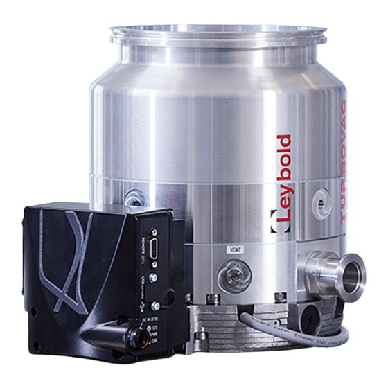
Fig. 1.1 TURBOVAC models Description The TURBOVAC 850 i and 950 i are turbomolecular pumps designed to evacuate vacuum chambers down to pressure levels in the high vacuum and ultra-high vacuum range. They are suitable for pumping air and clean gases. A forevacuum pump and a power supply are required for their operation. -
Page 9: Design
Turbomolecular pump with integrated electronic drive unit, two eye-bolts High and fore-vacuum flanges are protective-capped. Flange mounting elements, the DC In plug and the inlet screen are not enclosed, but are available as accessories, see Section 1.5. 300855170_002_C4 - 06/2020 - © Leybold... -
Page 10: Technical Data
* Please contact us when using Argon or other “heavy” gases as process gas. 1) * Depending on the ambient temperature, the gas throughput and the type of gas, forced air cooling or water cooling may be necessary. 300855170_002_C4 - 06/2020 - © Leybold... -
Page 11: Technical Data For The Integrated Drive Electronics
Overvoltage category Contamination grade Accessory connections 1 pc. M8 connector, 24 V DC Maximum load rating for the 24 V DC outputs 24 V, max. 18 W (powering accessories, e.g. cooling unit or valves) 300855170_002_C4 - 06/2020 - © Leybold... -
Page 12: Pumping Speed Curves
1.3.2 Pumping speed curves 1.000 TURBOVAC 850 i Helium Hydrogen Nitrogen Argon mbar Inlet pressure Fig. 1.2 Pumping speed curves for the TURBOVAC 850 i 1.000 TURBOVAC 950 i Helium Nitrogen Argon Hydrogen mbar Inlet pressure Fig. 1.3 Pumping speed curves for the TURBOVAC 950 i... -
Page 13: Operation Diagrams
TRIVAC D 65 B TRIVAC D 65 B SCROLLVAC 7 plus SCROLLVAC 7 plus DIVAC 3.8 HV3 DIVAC 3.8 HV3 Pressure in mbar Druck in mbar Fig. 1.4 Operation diagram for TURBOVAC 850 i 300855170_002_C4 - 06/2020 - © Leybold... - Page 14 TRIVAC D 65 B TRIVAC D 65 B SCROLLVAC 7 plus SCROLLVAC 7 plus DIVAC 3.8 HV3 DIVAC 3.8 HV3 Pressure in mbar Druck in mbar Fig. 1.5 Operation diagram for TURBOVAC 850 i 300855170_002_C4 - 06/2020 - © Leybold...
- Page 15 TRIVAC D 65 B TRIVAC D 65 B SCROLLVAC 7 plus SCROLLVAC 7 plus DIVAC 3.8 HV3 DIVAC 3.8 HV3 Pressure in mbar Druck in mbar Fig. 1.6 Operation diagrams for TURBOVAC 950 i 300855170_002_C4 - 06/2020 - © Leybold...
-
Page 16: Ordering Data
Power failure venting valve 24 V DC, G 1/8“ 800120V0022 Purge gas valve, 24 V DC, G 1/8“, 24 sccm 800120V0013 Purge gas throttle 24 sccm 800120V0014 Air filter for TMP, G 1/8“ 800110V0022 Air drier TURBOVAC on request 300855170_002_C4 - 06/2020 - © Leybold... - Page 17 Mounting kit TURBOVAC DN 160 ISO-K 800134V0030 + 267 01 DN 160 CF 800134V0031 DN 160 ISO-K to ISO-F 800134V0035 DN 200 ISO-K 268044 + 26701 (3x) DN 200 CF ES83946 + 83907 300855170_002_C4 - 06/2020 - © Leybold...
- Page 18 160 CF 202,5 200 ISO-K 250,5 200 CF 250,5 Ø 213 Ø a VENT 4x M8 -14 G 1/8" PURGE G 1/8" DN 25 KF 4x M5 -8 Fig. 1.7 Dimensional drawings, dimensions in mm 300855170_002_C4 - 06/2020 - © Leybold...
-
Page 19: Transport And Storing
The devices are delivered in safe transport packaging. Check whether the packaging has been damaged during transport. If that is the case, notify the freight forwarder and Leybold if necessary. Keep transport packaging for any further transportation and storage of the pump. -
Page 20: Installation
The turbomolecular pump must be bolted to a rigid vacuum system and con- nected to a suitable backing pump. It is intended for being operated within closed rooms. The use of any accessories which have not been specified by Leybold is only allowed after approval by Leybold. 3.1.1 Non-conforming utilization... -
Page 21: Operating Environment
In this case both devices will be switched parallelly (i.e. de-energised active / in-active). The factory-set accessories’s interface features a plug-and-play mode, and is instantly ready for operation with the connected device (ener- gised with pump switched on). 300855170_002_C4 - 06/2020 - © Leybold... -
Page 22: Attach The Pump To The Vacuum Chamber
(caused, for example, by solid objects from the process rotor seizes chamber entering the pump through the high vacuum flange), the following torques need to be absorbed by the system: TURBOVAC 850/950 i max. 10 kNm 300855170_002_C4 - 06/2020 - © Leybold... - Page 23 If several turbomolecular pumps are installed to the vacuum chamber of the same system, there is the risk of interference (vibration interference between the pumps). If such a risk exists please contact Leybold Application Support. The standard mounting arrangement for the pump is adequate to ensure earthquake protection.
- Page 24 18 mm 23 mm Recommended bolts – ISO 4014 for steel flanges M10x40 for aluminium flanges M10x45 Bolt quality 8.8 or A2(A4)-80 stainless steel bolts Fastening torque Fig. 3.2 Mounting high vacuum flange ISO-K 300855170_002_C4 - 06/2020 - © Leybold...
- Page 25 (accessories, optional) ■ The contact surfaces of pump housing, vacuum system and centering ring NOTICE must be free of grease and dry so as to ensure adequate strength in case the rotor should seize. 300855170_002_C4 - 06/2020 - © Leybold...
- Page 26 Minimum screw-in depth for steel 12 mm Recommended bolts for steel flanges – DIN 835 M8x30 M8x30 L1 = Bolt quality 8.8 or A2(A4)-70 stainless steel bolts Fastening torque Fig. 3.4 Mounting the CF high vacuum flange 300855170_002_C4 - 06/2020 - © Leybold...
-
Page 27: Forevacuum Connection
WARNING or the gases being pumped can react with air or humidity. Observe Safety Information 0.4. The forevacuum pump can be energised at the accessories connection of the TURBOVAC i via the relay box. 300855170_002_C4 - 06/2020 - © Leybold... -
Page 28: Connect The Cooling
The accessory con- nection is so pre-configured that the air cooler will always be running when the pump is running. To change this setting, refer to the interface Operating Instructions. 300855170_002_C4 - 06/2020 - © Leybold... -
Page 29: Water Cooling
With pump downtimes the cooling water has to be turned off. When switching the cooling water supply on and off by means of an electric- ally actuated valve, connect the valve so that it will be switched on and off together with the pump. 300855170_002_C4 - 06/2020 - © Leybold... -
Page 30: Water Quality
If there is the danger of frost, you may use a water glycol mixture of up to 30 %. DS water (softened or fully desalinated water) can be used for cooling the pump, if the pH value corresponds to the range indicated above. 300855170_002_C4 - 06/2020 - © Leybold... - Page 31 Example: Max. ambient temperature 25 °C Min. coolant inlet temperature 17 °C ⇒ Max. relative humidity °C Minimum coolant inlet temperature Abb. 3.7 Dewpoint diagram 300855170_002_C4 - 06/2020 - © Leybold...
-
Page 32: Connect A Power Failure Venting Valve Or A Venting Valve
Plug in the corresponding control cable into the accessories connection. For the electronic drive unit change the venting valve settings to venting operation (via the interfaces). 300855170_002_C4 - 06/2020 - © Leybold... -
Page 33: Connect Purge Gas
Purge gas connection with purge gas throttle Unscrew and remove the locking screw and the gasket from the purge gas connection of the pump. Then screw in the throttle and the gasket into the thread. 300855170_002_C4 - 06/2020 - © Leybold... -
Page 34: Connect A Flange Heater
The cable protection and voltage drop and the minimum supply voltage must be adhered to when wiring. When operating more than one pump with a single power supply, it may be necessary to fuse each pump separately due to the line protection. 300855170_002_C4 - 06/2020 - © Leybold... - Page 35 Fig. 3.11 Interfaces Earth (ground) connection We recommend fitting a separate earth (ground) conductor. The impedance between the pump body and the earth connection point must be < 0.1 Ω. Earth (ground) connector M6 - 8 300855170_002_C4 - 06/2020 - © Leybold...
- Page 36 Initialisation shortly after switching on the supply voltage Memory procedure in progress (power supply must not be interrupted) Reset of factory setting is ongoing Firmware update is ongoing Valid from firmware parameter P2: R02.09.01 Fig. 3.12 LEDs 300855170_002_C4 - 06/2020 - © Leybold...
- Page 37 1 and 2 connected (normal position) No error com. 1 and 9 connected Error n. c. Warning relay 14 and 15 connected (normal position) No warning com. 14 and 15 open Warning Fig. 3.13 REMOTE interface X1 300855170_002_C4 - 06/2020 - © Leybold...
- Page 38 Error has just occurred Start passive active Error is present; pump is at standstill Start passive active flashes Error is present; pump is decelerating Start passive active flashes Error has just occurred 300855170_002_C4 - 06/2020 - © Leybold...
-
Page 39: Operation
The PC software LeyAssist allows convenient access by the user to the para- meters of the frequency converter. Operating Instructions 300450826 Serial Interfaces for TURBOVAC i/IX offer a detailed description of the interfaces RS 232, RS 485, Profibus and USB of the TURBOVAC. 300855170_002_C4 - 06/2020 - © Leybold... - Page 40 This function is only changed after de-energising the may be used for other electrical con- pump and then restarting it. sumers and the pump is also decele- rated faster. 300855170_002_C4 - 06/2020 - © Leybold...
-
Page 41: Switching On
In the case of critical applications you must consult our Applications Dept. first. After a mains power failure the pump can run up automatically once more if a start command is present. 300855170_002_C4 - 06/2020 - © Leybold... -
Page 42: Shutting Down
■ apply a stop command via the interface ■ for the power supply units offered or recommended by Leybold switch off ■ the DC voltage. After switching off, the green status LED will flash until the rotor of the turbo- molecular pump is at standstill. -
Page 43: Venting
During venting, the flow Particles must be of the laminar type in both the vacuum chamber and the turbomo- lecular pump. The pump must not be vented to pressures above atmospheric pressure. 300855170_002_C4 - 06/2020 - © Leybold... -
Page 44: Bakeout
[0] is written to 0 by the electronics. For pumps that have been stored for more than 3 years, we recommend a preventive exchange of the ball bearings, see Section 5 Bearing replace- ment. 300855170_002_C4 - 06/2020 - © Leybold... -
Page 45: Removing The Pump From The System
Pack the pump so that it cannot be damaged during shipping and storage. Pay particular attention to protection for the flanges and the electrical plug. Observe the instructions in Section 5.2 if you forward the pump to Leybold. 300855170_002_C4 - 06/2020 - © Leybold... -
Page 46: Maintenance
Leybold Service Center or by the customer: please contact us for this. If you wish to exchange the bearings yourself, you will need a Leybold tool kit and spare ball bearings. Immediately after exchanging the bearings, let them run in, see Section 4.7. -
Page 47: Bearing Monitoring And Conditioning
Maintenance Bearing monitoring and conditioning To ensure maximum reliability and bearing life TURBOVAC 850 i and 950 i have an integrated system to manage the bearing condition. The status is indicated by a blue LED on the pump. The pumps have an integrated battery-backed real time clock that is con- stantly monitoring pump storage time. - Page 48 LED is permanently ON BRIM is running LED is flashing 0.25 s ON and 0.25 s Pump has been stored for more than 3 years, bearing replacement is required 300855170_002_C4 - 06/2020 - © Leybold...
-
Page 49: Troubleshooting
The pump can continue to run, as long as opera- tion limits are only exceeded for a short time. In case of longer exceeding send pump and fre- quency converter to the Leybold service. Turbomolecular pump Interface protocol error Use USS protocol. - Page 50 * Default values for normal operation threshold (P25) and max. run-up time (P32), can be changed via serial interface. 300855170_002_C4 - 06/2020 - © Leybold...
-
Page 51: Waste Disposal
6(a) Lead as an alloying element in steel for machining purposes and in galvanised steel containing up to 0,35 % lead by weight. 0.35% 6(b) Lead as an alloying element in aluminium containing up to 0.4% by weight . 0.4 % 6(c) Copper alloy containing up to 4% lead by weight. 300855170_002_C4 - 06/2020 - © Leybold... -
Page 52: Certificates
Certificate No. CU72191742.01 cTUVus File No. 31982384.001 The components are in compliance to the tested standards. The TÜV Rheinland of North America is a “Nationally Recognized Testing Laboratory” (NRTL) for the USA and Canada. 300855170_002_C4 - 06/2020 - © Leybold... -
Page 53: Eu Declaration Of Conformity
EU Declaration of Conformity 300855170_002_C4 - 06/2020 - © Leybold... - Page 54 Leybold GmbH Bonner Strasse 498 50968 Cologne GERMANY T: +49-(0)221-347-0 info@leybold.com www.leybold.com...
Need help?
Do you have a question about the TURBOVAC 850 i and is the answer not in the manual?
Questions and answers