Table of Contents

Related Manuals for LEYBOLD TURBOVAC 151


Summary of Contents for LEYBOLD TURBOVAC 151
- Page 1 TURBOVAC Turbomolecular pumps with external frequency converter TURBOVAC 151, 151 C TURBOVAC 361, 361 C TURBOVAC 600 C TURBOVAC 1000 C TURBOVAC 1100 C and pumps modified by Leybold Incorporation Declaration & Operating Instructions GA05118_002_C1...
-
Page 2: Table Of Contents
Forevacuum connection Connect the cooling Connecting the purge gas and venting device Connecting the frequency converter Operation Media compatibility / purge gas Start-up Switching on Shutting down Venting Bakeout Removing the pump from the system GA05118_002_C1 - 11/2017 - © Leybold... - Page 3 Contents Maintenance Cleaning Leybold Service Troubleshooting Waste Disposal EU Declaration of Conformity EC Declaration of Incorporation Original installation and operating instructions. GA05118_002_C1 - 11/2017 - © Leybold...
- Page 4 Operating Instructions and follow the information so as to ensure optimum and safe working right from the start. The Leybold TURBOVAC has been designed for safe and efficient operation when used properly and in accordance with these Operating Instructions. It is...
-
Page 5: Important Safety Information
To avoid the destruction of the equipment and to prevent injuries of the operating staff the leading European manufacturers of vacuum pumps strictly recommend to follow the installation instructions as given in this manual. GA05118_002_C1 - 11/2017 - © Leybold... -
Page 6: Electrical Hazards
When applying external voltages above 42 V to the connection termi- nals, observe the applicable VDE safety regulations! Make the electrical connections only after pump and accessories (e.g. air cooler) have been installed mechanically. GA05118_002_C1 - 11/2017 - © Leybold... -
Page 7: Thermal Hazards
Contaminated parts can be detrimental to health and environment. Before beginning with any work, first find out whether any parts are contaminated. Adhere to the relevant regulations and take the neces- sary precautions when handling contaminated parts. GA05118_002_C1 - 11/2017 - © Leybold... -
Page 8: Danger Of Ignition
Exposure of the pump to accelerating forces must be avoided or reduced to such an extent that the rotor unit will not be excited by vibrations. In the case of critical applications you must consult our Applications Dept. first. GA05118_002_C1 - 11/2017 - © Leybold... -
Page 9: Description
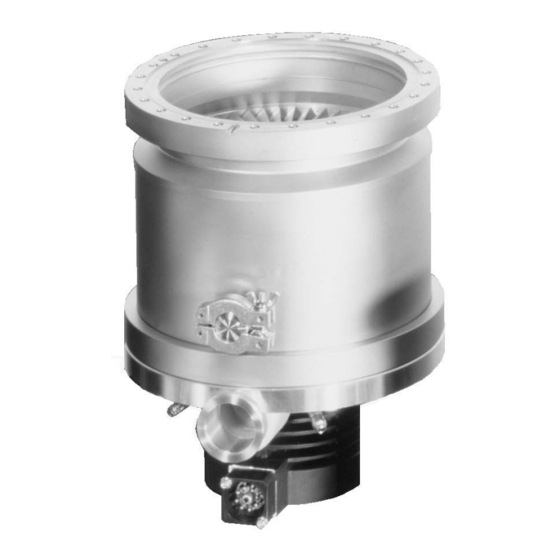
Both the purge gas port and the venting port are blank ed off for shipping. In addition the pivoted threaded fittings used to make the coolant connection are included as standard equipment for the TURBOVAC 151, 361 and 600; if needed, they can be used to replace the hose nipples installed at the factory. - Page 10 – 10 bis + 60 Max. bakeout temperature at CF flange °C High-vacuum port Electrical connection Vent port Connection for Purge water cooling gas port Forevacuum port Fig. 1.1 TURBOVAC 151 C; TURBOVAC 361 C similar GA05118_002_C1 - 11/2017 - © Leybold...
- Page 11 680 / 480 Max. ambient temperature °C at operation Storing temperature °C – 10 to + 60 – 10 to + 60 – 10 to + 60 Max. bakeout temperature °C at CF flange GA05118_002_C1 - 11/2017 - © Leybold...
- Page 12 TURBOVAC 1000 C / 1100 C A High-vacuum port B Forevacuum port C Vent port D Purge gas port E Connection for water cooling F Electrical connection Fig. 1.2 TURBOVAC 600 C, 1000 C, 1100 C GA05118_002_C1 - 11/2017 - © Leybold...
-
Page 13: Ordering Data
DN 100 CF, 230 V, 50 Hz 854 27 DN 100 CF, 110 V, 50 Hz 854 28 DN 160 CF, 230 V, 50 Hz 854 37 DN 160 CF, 110 V, 50 Hz 854 38 GA05118_002_C1 - 11/2017 - © Leybold... - Page 14 Description Air cooler TURBOVAC 151, 361, 230 V AC 855 31 TURBOVAC 151, 361, 110-115 V AC 800152V0016 TURBOVAC 600, 1000, 230 V AC 855 41 TURBOVAC 600, 1000, 110-115 V AC 800152V0017 Vibration absorber DN 100 ISO-K 800131V0100 DN 100 CF...
-
Page 15: Transport And Storing
Make sure that the product has not been damaged during transportation. If this unit is damaged contact your carrier and inform Leybold if necessary. For storage of the product, use the packaging pro vided. Be careful not to damage the sockets and connections during transporta- NOTICE tion. -
Page 16: Installation
Both pump and frequency converter are intended for being operated within closed rooms. The use of any accessories which have not been specified by Leybold is only allowed after approval by Leybold. 3.1.1 Non-conforming utilization... - Page 17 Storing in a humid atmosphere can cause corrosion. Conversions, manipulations and maintenance work by personnel not ■ authorised by Leybold. Any non-conforming utilisation of pump, frequency converter and accesso- WARNING ries can result in severe injury and cause damage to components. GA05118_002_C1 - 11/2017 - © Leybold...
-
Page 18: Operating Environment
Make the electrical connection for the ventilation unit in such a way that it will be started and stopped together with the pump itself. Observe the information given in the operating instructions for the air ventila- tion unit (GA 05199). GA05118_002_C1 - 11/2017 - © Leybold... -
Page 19: Attach The Pump To The Vacuum Chamber
In this case mount the turbomolecular pump separately. A vibration absorber cannot reliably sustain the high deceleration torque in case of a rotor seizure. If additional mounting is not possible, then the pump must be protected by a suitable shield during operation. GA05118_002_C1 - 11/2017 - © Leybold... - Page 20 If several turbomolecular pumps are installed to the vacuum chamber of the Vibration influence same system, there is the risk of interference (vibration interference between the pumps). If such a risk exists please contact Leybold Application Support. Earthquake protection The standard mounting arrangement for the pump is adequate to ensure earthquake protection.
- Page 21 During operation the pump can get so hot that there is the risk of suffer ing CAUTION burns (up to approximately 80 °C). Protect the hot parts against being touched. GA05118_002_C1 - 11/2017 - © Leybold...
- Page 22 M10x40 for aluminium flanges M8x35 M8x35 M10x45 M10x45 Bolt quality 8.8 or 8.8 or 8.8 or 8.8 or A2(A4)-70 A2(A4)-80 A2(A4)-80 A2(A4)-80 stainless steel bolts Fastening torque Fig. 3.2 Mounting high vacuum flange ISO-K GA05118_002_C1 - 11/2017 - © Leybold...
- Page 23 M10x35 for aluminium flanges M8x40 M8x40 M10x40 M10x40 Bolt quality 8.8 or 8.8 or 8.8 or 8.8 or A2(A4)-70 A2(A4)-80 A2(A4)-80 A2(A4)-80 stainless steel bolts Fastening torque Fig. 3.3 Mounting high vacuum flange ISO-K GA05118_002_C1 - 11/2017 - © Leybold...
- Page 24 – DIN 835 M8x30 M8x30 M8x30 M8x35 L2 = L3 = 17,5 24,5 Bolt quality 8.8 or A2(A4)-70 stainless steel bolts Fastening torque Fig. 3.4 Mounting the CF high vacuum flange GA05118_002_C1 - 11/2017 - © Leybold...
-
Page 25: Forevacuum Connection
Ensure that the pump is sufficiently isolated against vibrations generated by the forevacuum pump. No forces from the piping system may be allowed to affect the turbomolecu- lar pump. Support the piping correspondingly or decouple through flexible joints. GA05118_002_C1 - 11/2017 - © Leybold... -
Page 26: Connect The Cooling
Aggressive carbon dioxide None, not detectable Chloride < 100 mg/l Sulphates < 150 mg/l Nitrate ≤ 50 mg/l Iron < 0.2 mg/l Manganese < 0.1 mg/l Ammonium < 1.0 mg/l Free chlorine < 0.2 mg/l GA05118_002_C1 - 11/2017 - © Leybold... - Page 27 When switching the cooling water supply on and off by means of an electric- ally actuated valve, connect the valve so that it will be switched on and off together with the pump. GA05118_002_C1 - 11/2017 - © Leybold...
- Page 28 Example: Max. ambient temperature 25 °C Min. coolant inlet temperature 17 °C ⇒ Max. relative humidity °C Minimum coolant inlet temperature Fig. 3.6 Dewpoint diagram GA05118_002_C1 - 11/2017 - © Leybold...
-
Page 29: Connecting The Purge Gas And Venting Device
Consider the additional purge gas flow when selecting a suitable backing pump. We recommend a purge gas flow (with Nitrogen) of 0,4 mbar·l/s (24 sccm) for the TURBOVAC 151 C and 361 C and ■ 0,6 mbar·l/s (36 sccm) for the TURBOVAC 600 C, 1000 C and 1100 C. -
Page 30: Connecting The Frequency Converter
The connections are of the IP 40 safety classification. Do not expose the pump, frequency converter or connectors to dripping water. TURBOVAC 600 C,1000 C and 1100 C from year of production 2007 must not be operated with the TURBOTRONIK NT 1000/1500. GA05118_002_C1 - 11/2017 - © Leybold... - Page 31 — — — — Roughing pump line; recommended to achieve the shortest possible cycling times — · — · — · — · Drive and control line Fig. 3.7 Schematic of a turbomolecular pump system GA05118_002_C1 - 11/2017 - © Leybold...
-
Page 32: Operation
Change the filters after some time, at least annually. Start-up Turbomolecular pumps which were not operated for a period of over 12 months should be returned to us. For more information on this please con- tact your local sales partner. GA05118_002_C1 - 11/2017 - © Leybold... -
Page 33: Switching On
Exposure of the pump to accelerating forces must be avoided or reduced NOTICE to such an extent that the rotor unit will not be excited by vibrations. In the case of critical applications you must consult our Applications Dept. first. GA05118_002_C1 - 11/2017 - © Leybold... -
Page 34: Shutting Down
If a failure occurs the turbomolecular pump will be shut down automatically. The red LED at the frequency converter lights up. Unplug any connectors only when the mains voltage is switched off and CAUTION the pump does no longer turn (the green LED is off). GA05118_002_C1 - 11/2017 - © Leybold... -
Page 35: Venting
The speed of the pressure rise during venting of the running pump will greatly influence the load on the rotor/stator pack and the bearings. The pump must not be vented to pressures above atmospheric pressure. GA05118_002_C1 - 11/2017 - © Leybold... -
Page 36: Bakeout
Pack the pump so that it cannot be damaged during shipping and storage. Pay particular attention to protection for the flanges and the electrical plug. Observe the instructions in Section 5.2 if you forward the pump to Leybold. A packing set is included with TURBOVAC models with a “C” in the type designation. -
Page 37: Maintenance
We recommend an exchange of the rotor unit after 80,000 operating hours at Rotor exchange the latest. Such maintenance work can only be done by the Leybold Service. If required contact the Leybold service center nearest to your location. You can find the address on our internet page www.leybold.com. -
Page 38: Troubleshooting
Check the water flow monitoring device by jumping its terminals and start- ing the TURBOVAC. Is the forevacuum pressure sufficient? ■ Is the vacuum chamber free of leaks? ■ Observe also the troubleshooting instructions for the frequency converter. GA05118_002_C1 - 11/2017 - © Leybold... - Page 39 Department). vibrations. Bearing is defective. Bearings will have to be replaced (only by the Leybold Service Department). Pump running within the natural frequency Change the masses of the system or install vibration range of the system, causing resonance.
-
Page 40: Waste Disposal
Separate clean components according to their materials, and dispose of these accordingly. We offer this service. Further details are available on request. When sending us any equipment, observe the regulations given in Section “5.2 Leybold service”. GA05118_002_C1 - 11/2017 - © Leybold... -
Page 41: Eu Declaration Of Conformity
EU Declaration of Conformity GA05118_002_C1 - 11/2017 - © Leybold... -
Page 42: Ec Declaration Of Incorporation
EC Declaration of Incorporation GA05118_002_C1 - 11/2017 - © Leybold... - Page 43 Person to contact: Calibration: Factory-calibr. Phone : Fax: Quality test certificate DIN 55350-18-4.2.1 End user: A. Description of the Leybold product: Failure description: Material description : Catalog number: Additional parts: Serial number: Application-Tool: Type of oil (ForeVacuum-Pumps) : Application- Process: B.
- Page 44 Sales and Service Germany America Great Britain Leybold Japan Co., Ltd. Tsukuba Technical Service Center 1959, Kami-yokoba Leybold UK LTD. Leybold GmbH Tsukuba-shi, Ibaraki-shi 305-0854 Unit 9 Sales, Service, Support Center (3SC) Japan Silverglade Business Park Leybold USA Inc. Bonner Strasse 498...
Need help?
Do you have a question about the TURBOVAC 151 and is the answer not in the manual?
Questions and answers