
Related Manuals for LEYBOLD E 250


Summary of Contents for LEYBOLD E 250
- Page 1 LEYBOLD VACUUM Vacuum Solutions Application Support Service GA 02.200/8.02 E and DK - Pumps Rotary Piston Pumps E 250, DK 200 Cat. No. 105 36 111 16 895 08 895 09 895 10 166 17 166 37 Operating Instructions...
-
Page 2: Table Of Contents
Leybold Service .....23 such a way that the type of contamination is apparent. -
Page 3: Description
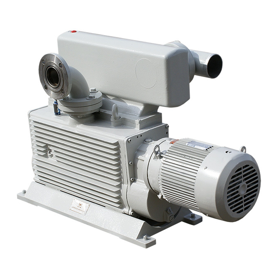
Description Fig. 1 Rotary Piston Pump E 250 1 Description 1.1 Design and Principle of 1.1.1 Principle of Operation Operation In the pump body (2/14), the piston (2/1) is guided by the eccentrically mounted cam (2/2) along the wall of the The E series comprises single-stage rotary piston pumping chamber, without contacting it. -
Page 4: Design
Description Key to Fig. 2 Piston Drive shaft Oil channel Exhaust valve Oil-level glass Exhaust box Gas ballast activator Dirt trap 10 Inlet port 11 Piston neck 12 Slide valve 13 Cooling fins 14 Pump body Fig. 2 Cross-section of rotary piston pump and principle of operation 1.1.2 Design This prevents condensation of vapours in the pump up to the vapour tolerance specified in the Technical Data. -
Page 5: Transporting
When shelving the pump for over one year, you should run maintenance on the pump and also do an oil change before putting the pump into service again. We recom- mend that to get in touch with Leybold Service in such a case. GA 02.200/8.02 - 10/02... -
Page 6: Technical Data And Accessories
Description ød E 250/DK 200 63 ISO-K 63 ISO-K 1190 E 250/DK 200 63 ISO-K 63 ISO-K Dimension “a” applies only in connection with the standard type of motor used by us Without adaptor Fig. 4 Dimensional drawing 1.3 Technical Data and Accessories... -
Page 7: Lubricants
Description Accessories E 250 DK 200 -- Cat. Nos. -- Vibration absorbing feet 101 55 101 55 Seal kit 192 63 192 63 Dust separator 178 02 178 02 Dust filter 278 17 278 17 Separator (intake side) 188 45... -
Page 8: Operation
Description 2 Operation 2.1 Installation Install the pump on a flat, horizontal surface. The base of the pump must be supported evenly and horizontally at the four points of contact. If the pump stands on a level Warning The standard pump is not suited for instal- floor, it is not necessary to bolt it down unless the inlet lation in explosion hazard areas. -
Page 9: Electrical Connections
(see marking on motor hood). Warning For all work on the wiring, disconnect the When connecting a condenser to the E 250 line cords from the mains. and DK pumps - without motor - it must be The electrical connections must only be... -
Page 10: Connection To Vacuum System
Operation 2.3 Connection to Vacuum 2.3.2 Exhaust Side System Warning The exhaust gases must be lead away safe- ly and - if required - subjected to suitable (see Fig. 7) post-processing. If you have not already done so, remove the temporary covers from the inlet and exhaust ports. -
Page 11: Start-Up
Operation The pressure in the exhaust line must be greater than 2.5.2 Pumping of Condensable Gases and 500 mbar (abs.) so that the pressure differential (in rela- Vapours tion to the pumping chamber) needed for lubrication is With the gas ballast valve open and at operating tempe- maintained. -
Page 12: Shutdown And Storage
Operation 2.6 Shutdown and Storage Drain the oil (see Section 3.3). Fill the pump with fresh oil (see Section 3.3) and let it run for a while. Warning • When the pump has been switched off while warm, it may not be switched on Drain the oil again and fill the pump with fresh oil once immediately again. -
Page 13: Maintenance
Pump 1 day Gear 1 week If you send a pump to Leybold for repair, please specify all hazardous substances in or around the pump. Please use the special Check condition depends very much form for this which has been included with... -
Page 14: Checking The Condition Of The Oil And The Oil Level
Gas ballast activator Oil-level glass Eyebolts for lifting Exhaust box Oil-fill plug screw, pumping chamber Sealing disk Collar flange: E 250, DK 200 Clamping ring 10 Exhaust port 11 Collar flange 12 Snap ring 13 Dirt trap 14 Oil-fill plug screw, gear... -
Page 15: Oil Change
Maintenance 3.3 Oil Change Caution Use only the original oil-fill plug or the pro- per spare. This plug contains a venting devi- 3.3.1 Pumping Chamber ce for avoiding excessive pressure in the gear housing. Always carry out the oil change when the pump is shut down but still warm. -
Page 16: Disassembling And Reassembling The Pump
Maintenance 3.6 Disassembling and Reassembling the Pump Warning This kind of work should be left to trained 3.6.2 Disassembling the Valves and Oil personnel. At this point we recommend our Level Glass practical training courses. Please note especially the safety informati- Remove the exhaust box (7/5). - Page 17 Maintenance Key to Fig. 8 Gas ballast activator Oil-level glass Exhaust and gas ballast valve assembly Valve holder without oil drain groove Gas ballast adaptor T-screw connection Silencer nozzle Tubing Valve holder with oil drain groove (on two-stage pumps only) Fig.
-
Page 18: Disassembling The Motor End
If the parts (9/20) to (9/26) do not have to be replaced, To remove the piston and cam from the middle pumping mark them or place them in the right order for reassem- chamber on E 250 and DK 200, see Section 3.6.5. bly. Unscrew the outer race (9/20). - Page 19 Maintenance Key to Fig. 9 Piston Piston bushings Slide valve O-ring Tapered dowel pins Radial shaft seal Front end plate Three-phase motor 10 Spacer bushing 11 Pinion gear 12 Spacer bushing 13 Screw 14 Gasket 15 Gear box 16 Gasket 17 Retainer ring 18 Ring gear 19 Spacer...
-
Page 20: Disassembling The Front End
Maintenance Key to Fig. 10 1 Tapered dowel pin 2 Rear end plate 3 O-ring 4 Slide valve 5 O-ring 6 Side cover 7 Cam 8 Piston bushing 9 Piston 10 Shaft bushing 11 O-ring 12 O-ring 13 Gasket ring 14 Oil-drain plug screw Fig. -
Page 21: Removing The Shaft And Intermediate Plate(S)
14 Tapered pin 15 Foot Fig. 11 Removing the shaft and intermediate plate(s); removing the middle piston and cam on E 250 and DK 200 3.6.5 Removing the Shaft and Intermediate If the piston bushings (11/7) are damaged, force them out of the piston (11/6). -
Page 22: Cleaning The Parts And Checking For Wear
Maintenance Key to Fig. 12 L-ring shaft seal (8/27) Oil flow holes Circular spring on ID of radial shaft seal Radial shaft seal (8/7) Bottom surface of bearing well Spacer (8/26) Front end plate (8/8) Retainer ring (8/25) Bearing (8/24) 10 Ring gear (8/18) 11 Shims (8/23) 12 Retainer ring (8/17) -
Page 23: Leybold Service
When withdrawing the sleeve tool, hold the L-ring shaft seal tight. If a pump is returned to LEYBOLD, indicate whether the pump free of substances damaging to health or whether The spacer (9/26) has an oil channel, which must point it is contaminated. -
Page 24: Troubleshooting
Troubleshooting 4 Troubleshooting Fault Possible cause Remedy Repair note Pump does not Motor is connected incorrectly. Connect the motor correctly (wiring diagram in junction box). start. Reverse lock prevents start-up. Interchange two of the input leads at motor junction box or install the reverse lock correctly. - Page 25 Troubleshooting Fault Possible cause Remedy Repair- note Pump gets hotter Air intake or discharge surfaces of the cooler Set up the pump correctly or clean the cooler. than previously are obstructed or dirty. observed. Ambient or intake temperatures are too high. 40 °C max.
-
Page 26: Ec Declaration Of Conformity
EC Declaration of Conformity We - Leybold Vacuum GmbH - herewith declare that the The products conform to the following directives: products defined below meet the basic requirements • EC Directive on Machinery (98/37/EG) regarding safety and health of the relevant EC directives by design, type and the versions which are brought in to •... -
Page 27: Eec Manufacturer's Declaration
EEC Manufacturer’s Declaration in the sense of the Directive on Machinery 89/392/EWG, Annex IIb Applied harmonised standards: We – Leybold Vacuum GmbH – herewith declare that operation of the incomplete machine defined below, is • DIN EN 292 Part 1 11.91... - Page 28 GA 02.200/8.02 - 10/02...
- Page 29 GA 02.200/8.02 - 10/02...
- Page 30 Sales Net Worldwide AMERICA EUROPE ASIA USA: Germany Great Britain/Ireland: Peoples Republic of Singapore: LEYBOLD VACUUM USA LEYBOLD VAKUUM LEYBOLD LTD. China: BALZERS and LEYBOLD 5700 Mellon Road GmbH Waterside Way, LEYBOLD (Tianjin) Singapore Pte. Ltd. Export, PA 15632 Bonner Straße 498...
Need help?
Do you have a question about the E 250 and is the answer not in the manual?
Questions and answers