
Subscribe to Our Youtube Channel
Related Manuals for LEYBOLD MAG integra Series


Summary of Contents for LEYBOLD MAG integra Series
- Page 1 MAG integra Turbomolecular Pumps with Magnetic Bearing and Frequency Converter Installation & Operating Instructions 300324726_002_C0 Part Nos. 411300Vxxxx 411600Vxxxx 411700Vxxxx 412200Vxxxx and pumps modified by Leybold...
-
Page 2: Table Of Contents
Attach the pump to the vacuum chamber Forevacuum connection Connecting the cooling water 3.5.1 Water Quality Connect the purge gas and venting valve Electrical connection for the integrated frequency converter Relays, LEDs, PLC interface 300324726_002_C0 - 10/2016 - © Leybold... - Page 3 Operation Switching off Venting Removing the pump from the system Maintenance Cleaning Changing the touch-down bearings Leybold Service Troubleshooting Waste Disposal EC Incorporation Declaration EC Declaration of Conformity Certificates Original installation and operating instructions. 300324726_002_C0 - 10/2016 - © Leybold...
- Page 4 Operating Instructions and follow the information so as to ensure optimum and safe working right from the start. The Leybold MAG integra has been designed for safe and efficient opera- tion when used properly and in accordance with these Operating Instructions.
-
Page 5: Important Safety Information
To avoid the destruction of the equipment and to prevent injuries of the operating staff the leading European manufacturers of vacuum pumps strictly recommend to follow the installation instructions as given in this manual. 300324726_002_C0 - 10/2016 - © Leybold... -
Page 6: Electrical Hazards
When applying external voltages above 42 V to the connection termi- nals, observe the applicable VDE safety regulations! Make the electrical connections only after pump and accessories (e.g. air cooler) have been installed mechanically 300324726_002_C0 - 10/2016 - © Leybold... -
Page 7: Thermal Hazards
Contaminated parts can be detrimental to health and environment. Before beginning with any work, first find out whether any parts are contaminated. Adhere to the relevant regulations and take the neces- sary precautions when handling contaminated parts. 300324726_002_C0 - 10/2016 - © Leybold... -
Page 8: Danger Of Ignition
120°C internally, and at parts of the outside surfaces 80 °C. Sparks could occur in case of damage to the pump and these could ignite explosive mixtures. Also note the safety information provided by the gas supplier. 300324726_002_C0 - 10/2016 - © Leybold... -
Page 9: Risk Of Damaging The Pump
Connect the pump in an EMC compliant manner so as to avoid line related interference. Pressures given in bar or mbar are absolute values. If exceptionally a gauge pressure is meant, a “g” is added (bar(g)). 300324726_002_C0 - 10/2016 - © Leybold... -
Page 10: Description
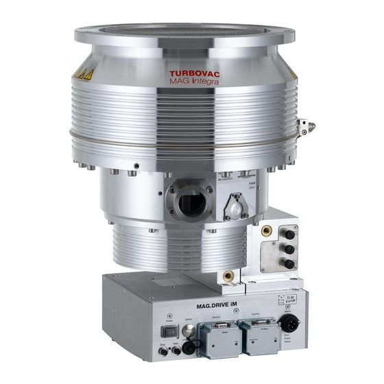
MAG W 2200 iP MAG W 2200 iPL Fig. 1.1 MAG integra models Description The Leybold MAG integra pumping system consists of: The MAG integra turbo pump ■ The MAG are turbomolecular pumps uti li zing magnetic bearings.They are designed to evacuate va cuum chambers down to pressure values in the high-vacuum range. -
Page 11: Design And Function
100 Hz and will then touch down on the touchdown bearings. The MAG has a purge gas device. It is water-cooled. A controlled synchronous motor is used to power the rotor. 300324726_002_C0 - 10/2016 - © Leybold... -
Page 12: Supplied Equipment
The frequency converter has the following interfaces: a Profibus or another optional interface, see Section 4.2 ■ an interface for the Leybold Service (RS 232) and ■ three connections for accessories, e.g. valves. ■... -
Page 13: Technical Data
25 °C and a forevacuum pump system having a pumping speed of over 600 m /h. These values may differ for other operating conditions. 2) Maximum gas throughput and maximum forevacuum pressure cannot be attained simultaneously. 300324726_002_C0 - 10/2016 - © Leybold... - Page 14 Temperature during operation 10 - 45 °C Storage temperature – 10 - 60 °C Relative air humidity (non condensing) 5 to 85 % Type of protection IP 54 Overvoltage category Contamination level acc. to IEC 61010 300324726_002_C0 - 10/2016 - © Leybold...
- Page 15 Nitrogen Argon Argon mbar Hochvakuumdruck Inlet pressure MAG W 1300 mbar·l/s temporary Stickstoff Nitrogen Argon Argon Continuous operation mbar Vorvakuumdruck Pressure Fig. 1.3 Pumping speed curves and operation diagrams for the MAG W 1300 300324726_002_C0 - 10/2016 - © Leybold...
- Page 16 Argon 1200 1000 mbar Hochvakuumdruck Inlet pressure MAG W 1600 temporary mbar·l/s Nitrogen Stickstoff Argon Argon Continuous operation mbar Vorvakuumdruck Pressure Fig. 1.4 Pumping speed curves and operation diagrams for the MAG W 1600 300324726_002_C0 - 10/2016 - © Leybold...
- Page 17 Argon Argon 1000 mbar Hochvakuumdruck Inlet pressure MAG W 1700 mbar·l/s temporary Stickstoff Nitrogen Argon Argon Continuous operation mbar Vorvakuumdruck Pressure Fig. 1.5 Pumping speed curves and operation diagrams for the MAG W 1700 300324726_002_C0 - 10/2016 - © Leybold...
- Page 18 1400 1200 1000 mbar Hochvakuumdruck Inlet pressure MAG W 2200 mbar·l/s temporary Stickstoff Nitrogen Argon Argon Continuous operation mbar Druck Pressure Fig. 1.6 Pumping speed curves and operation diagrams for the MAG W 2200 300324726_002_C0 - 10/2016 - © Leybold...
- Page 19 200 ISO-F 200 CF – – – 1600/1700 250 ISO-F 250 CF – 2200 250 ISO-F 250 CF – 1) 4 mm for cooling coil Fig. 1.7 Dimensional drawing of the pumps, dimensions in mm 300324726_002_C0 - 10/2016 - © Leybold...
-
Page 20: Ordering Data
* The IP 54 type of protection is only ensured with an IP 54 protection cap on the customer interface. Pump versions without IP 54 protection cap can only be classified as IP 20. Please consult with us for an optional IP 54 protection cap. 300324726_002_C0 - 10/2016 - © Leybold... -
Page 21: Accessories
0.6 mbar·l/s at 1.5 to 6 bar 121 33 0.6 mbar·l/s at 1 to 1.5 bar 800152V0010 Cable set (2 pieces) for connection to the pump 411300V01 Cooling water valve kit 411300V02 800152V0013 800110V0011 800110V0012 300324726_002_C0 - 10/2016 - © Leybold... -
Page 22: Transport And Storing
Keep the packaging Make sure that the product has not been damaged during transportation. If this unit is damaged contact your carrier and inform Leybold if necessary. To prevent damages to the pump, use the packaging pro vided for storage and transport. -
Page 23: Installation
Both pump and frequency converter are intended for being operated within closed rooms. The use of any accessories which have not been specified by Leybold is only allowed after approval by Leybold. The supplied integrated MAG.DRIVE iM frequency converter will be required for the operation of the turbomolecular pump. - Page 24 Storing in a humid atmosphere can cause corrosion. Conversions, manipulations and maintenance work by personnel not ■ authorised by Leybold. Any non-conforming utilisation of pump, frequency converter and accesso- WARNING ries can result in severe injury and cause damage to components. 300324726_002_C0 - 10/2016 - © Leybold...
-
Page 25: Operating Environment
35 kNm maximum needs to be absorbed by the system, should the pump suddenly seize. We have successfully tested the pumps in agreement with ISO 27892 both against crashes and also bursts. 300324726_002_C0 - 10/2016 - © Leybold... - Page 26 ISO 3669 (CF flange connections). Basically the frequency converter can be detached from the pump. However, this must only be done by an expert trained by Leybold. For this consult with Mount the turbomolecular pump as close as possible to the vacuum chamber.
- Page 27 If several turbomolecular pumps are installed to the vacuum chamber of the Vibration influence same system, there is the risk of interference (vibration interference between the pumps). If such a risk exists please contact Leybold Application Support. The standard pump fixing is sufficient for earthquake protection. If required fix Earthquake protection the system to the bottom or to the walls.
- Page 28 Mount the turbomolecular pump according to Fig 3.5 and tighten the bolts crosswise step-by-step. When the pump shall be baked out, the threads of the bolts should have been lubricated with a high temperature lubricant. 300324726_002_C0 - 10/2016 - © Leybold...
- Page 29 During operation the pump can get so hot that there is the risk of suffer ing CAUTION burns (up to approximately 120 °C). Protect the hot parts against being touched. 300324726_002_C0 - 10/2016 - © Leybold...
-
Page 30: Forevacuum Connection
When using a backing pump not having an integrated an ti-suckback valve, a separate safety valve should be used. The safety valve keeps oil from back- streaming from the backing pump and into the turbomolecular pump when the system is not running. 300324726_002_C0 - 10/2016 - © Leybold... -
Page 31: Connecting The Cooling Water
(n < 15 Hz) thereby preventing the formation of conden- sate within the pump. Install the valve as depicted in fig. 3.7 and electrically connect it to the frequency converter, see fig. 3.11. 300324726_002_C0 - 10/2016 - © Leybold... -
Page 32: 3.5.1 Water Quality
7.0 to 9,0 Total hardness (total alkaline earths) < 8 °dH Aggressive carbon dioxide None, not detectable Chloride < 100 mg/l Sulfate < 150 mg/l Nitrate ≤ 50 mg/l Iron < 0.2 mg/l 300324726_002_C0 - 10/2016 - © Leybold... - Page 33 If there is the danger of frost, you may use a water glycol mixture of up to 30 %. DS water (softened or fully desalinated water) can be used for cooling the pump, if the pH value corresponds to the range indicated above. 300324726_002_C0 - 10/2016 - © Leybold...
-
Page 34: Connect The Purge Gas And Venting Valve
Connect the purge gas and the venting valve recommended by us according to its instructions. The valve cables can be connected directly at the pump. When doing so, do not confuse “Purge” and “Vent”! 300324726_002_C0 - 10/2016 - © Leybold... -
Page 35: Electrical Connection For The Integrated Frequency Converter
In order to comply with the standard SEMI S2, install an additional mains power circuit breaker at the sides of the system. The short-circuit switch-off capacity of this mains power circuit breaker needs to be rated at 10,000 A minimum. 300324726_002_C0 - 10/2016 - © Leybold... -
Page 36: Relays, Leds, Plc Interface
Error has just occurred Start passive active Error is present; pump is at standstill Start passive active flashes Error is present; pump is decelerating Start passive active flashes Error has just occurred 300324726_002_C0 - 10/2016 - © Leybold... - Page 37 (0.3 s): Start delay active Normal operation Yellow LED PWR and green LED STS (flash fast Running down, brake operation at n < 100 Hz alternately i.e. venting is possible: option) 300324726_002_C0 - 10/2016 - © Leybold...
-
Page 38: Operation
The address for the Fieldbus module can be set via the RS 232 service inter- face or at the address switches. The set default address is 126dec = 7Ehex. 300324726_002_C0 - 10/2016 - © Leybold... -
Page 39: Switching On
Do not stop the Mag with the mains. Use a stop command. Switching off ■ the mains while the pump is running will wear out the touch down bear- ings. If the mains supply has been disconnected accidently re-connect it. 300324726_002_C0 - 10/2016 - © Leybold... -
Page 40: Switching Off
In the case of an emergency shut down, the pump is switched off as de scribed above. The rotor of the turbomolecular pump may be stopped faster by controlled venting the pump, see Fig. 4.1. 300324726_002_C0 - 10/2016 - © Leybold... -
Page 41: Venting
When venting the pump through its foreline connection, neither oil nor parti- Foreline connection cles may be entrained in the gas flow from the forevacuum side into the pump. 300324726_002_C0 - 10/2016 - © Leybold... -
Page 42: Removing The Pump From The System
Pack the pump so that it cannot be damaged during shipping and storage. Pay particular attention to protection for the flanges and the electrical plug. Observe the instructions in Section 5.3 if you forward the pump to Leybold. 300324726_002_C0 - 10/2016 - © Leybold... -
Page 43: Maintenance
Rotor exchange or 20,000 cycles at the latest. Such maintenance work can only be done by the Leybold Service. If required contact the Leybold service center nearest to your location. You can find the address on our internet page www.leybold.com. -
Page 44: Changing The Touch-Down Bearings
(def- ault 1000 contacts or 1 hour). In this case maintenance is required. Only the Leybold service can change the touch-down bear ings. Leybold Service Whenever you send us in equipment, indicate whether the equipment is con- taminated or is free of substances which could pose a health hazard. -
Page 45: Troubleshooting
LED is on” short time. Yellow LED flashes. Warning message: Supply voltage The pump can continue to run. Check the Operator/ too low or too high. reason for wrong voltage and eliminate maintenance staff the fault. 300324726_002_C0 - 10/2016 - © Leybold... -
Page 46: Waste Disposal
Separate clean components according to their materials, and dispose of these accordingly. We offer this service. Further details are available on request. When sending us any equipment, observe the regulations given in Section “5.3 Leybold service”. 300324726_002_C0 - 10/2016 - © Leybold... -
Page 47: Ec Incorporation Declaration
EC Incorporation Declaration 300324726_002_C0 - 10/2016 - © Leybold... -
Page 48: Ec Declaration Of Conformity
EC Declaration of Conformity 300324726_002_C0 - 10/2016 - © Leybold... -
Page 49: Certificates
Laboratory” (NRTL) for the USA and Canada. This product has been tested to the requirements of CAN/CSA-C22.2 No. 61010-1, third edition, including Amendment 1, or a later version of the same standard incorporating the same level of testing requirements. 300324726_002_C0 - 10/2016 - © Leybold... - Page 50 Person to contact: Calibration: Factory-calibr. Phone : Fax: Quality test certificate DIN 55350-18-4.2.1 End user: A. Description of the Leybold product: Failure description: Material description : Catalog number: Additional parts: Serial number: Application-Tool: Application- Process: Type of oil (ForeVacuum-Pumps) : B.
- Page 51 Notes 300324726_002_C0 - 10/2016 - © Leybold...
- Page 52 Sales and Service Germany America Great Britain Leybold Japan Co., Ltd. Tsukuba Technical Service Center 1959, Kami-yokoba Leybold UK LTD. Leybold GmbH Tsukuba-shi, Ibaraki-shi 305-0854 Unit 9 Sales, Service, Support Center (3SC) Japan Silverglade Business Park Bonner Strasse 498 Leybold USA Inc.
Need help?
Do you have a question about the MAG integra Series and is the answer not in the manual?
Questions and answers