Table of Contents

Related Manuals for LEYBOLD TURBOVAC TW 700


Summary of Contents for LEYBOLD TURBOVAC TW 700
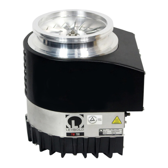
- Page 1 LEYBOLD VACUUM Vacuum Solutions Application Support Service GA 05.147/3.02 TURBOVAC TW 700 Turbomolecular Pump with Integrated Frequency Converter Cat. No. 800051V0001 to 800051V0007 and modified pumps Operating Instructions...
-
Page 2: Table Of Contents
4.1 Cleaning ......31 4.2 Service by LEYBOLD ....31 We would be glad to consult with you as regards the media which can safely be handled with this unit. -
Page 3: Standard Equipment
Description High-vacuum connection flange Rotor / Turbomolecular pumping stage Stator Ceramic ball bearings Rotor / Holweck pumping stage Motor Ceramic ball bearings Space for the frequency converter Fig. 1 Section through a TW 700; simplified representation 1.2 Standard equipment The pump is driven by a canned DC motor. In this motor the rotor and stator windings are separated by a vacu- um-tight can. -
Page 4: Ordering Data
Description 1.3 Ordering data Part No. Remarks ——————————————————————————————————————————————————— TURBOVAC TW 700 DN 160 ISO-K, air cooled, RS 232 interface 800051V0001 (previous 864 31) DN 160 ISO-K, water cooled, RS 485 interface 800051V0003 (previous 864 37) DN 160 ISO-K, air cooled, RS 485 interface... - Page 5 230 02 106 Adapter G 1/8“ — NPT 1/8“ 200 12 742 Gasket 238 20 110 ——————————————————————————————————————————————————— Recommended forevacuum pumps • TRIVAC B series, ECODRY series see Leybold catalog • Diaphragm pump DIVAC 4.8 VT 127 92 GA 05.147/3.02 - 06/2002...
-
Page 6: Technical Data
Description 1.4 Technical data Technical data for the integrated frequency converter TURBO.DRIVE L Technical data for pumps Nominal supply voltage 59 V DC Residual ripple < 2% High-vacuum connection DN 160 ISO-K max. supply voltage 60 V DC DN 160 CF min. - Page 7 Description mbar High-vacuum pressure Fig. 2 Pumping speed curves for the TURBOVAC TW 700 GA 05.147/3.02 - 06/2002...
- Page 8 Description Ø a ISO-K 115,5 78,3 Warning label under the pump; means „Warning: heat generation“ Ø a DN 160 ISO-K 39.5 DN 200 CF 49.5 24.5 DN 160 CF 202.5 48.5 Fig. 3 Dimensional drawing, dimensions in mm 7 x M4 Live 0 V DC –O/P...
-
Page 9: Connections
Do not remove the covers and blank flanges on the 1000 m heat dissipation by the ambient air is impaired. pump until just before attachment to the equipment to For higher places of installation, please ask Leybold. ensure that assembly is carried out under the cleanest possible conditions. - Page 10 Connections ISO-K version, High-vacuum air-cooled connector flange Purge gas connection Borehole M8, suitable for crane eyelet Cooling air inlets Forevacuum connection RS485 Interface connector REMOTE (X1) ERROR POWER (RS 232 or 485) STATUS TURBO.DRIVE (drawn without protective cap) 59 V DC power supply PLC interface* REMOTE (X1) CF version,...
-
Page 11: Attaching The Pump To The Vacuum Chamber
The order numbers for the flange components are given If foreign objects could pass from the vacuum chamber in the Leybold Catalog. into the pump, install a wire mesh splinter guard. Foreign objects which enter the pump through the intake can cause serious damage to the rotor. -
Page 12: Forevacuum Connection
Connections Centering ring KF flange from the forevacuum line Clamping yoke Screws Fig. 8 Connecting the forevacuum line 2.3 Forevacuum connection To ensure that the forevacuum space in the turbomole- cular pump is kept largely free of oil vapors during ope- ration as well, we recommend installing an adsorption We recommend using a dry-running diaphragm vacuum trap in the forevacuum line. - Page 13 Connections Legend for Fig. 9 1 Turbomolecular pump 2 Forevacuum gauge port 3 Forevacuum pump 4 Vibration absorber 5 Adsorption trap 6 Forevacuum valve 7 Purge gas and venting valve 8 High-vacuum valve 9 Valve in the roughing pump line —...
-
Page 14: Cooling The Pump
Connections operation not possible mbar·l/s water cooling required, see Fig. 12, max. ambient temperature: 45 °C (113 °F) air cooling required, max. ambient temperature 25 °C (77 °F) air cooling required, max. ambient temperature 45 °C (113 °F) convection cooling sufficient, mbar max. - Page 15 Connections Fig. 11 Cooling air flow pattern °C Cooling water temperature Fig. 12 Cooling water requirement GA 05.147/3.02 - 06/2002...
-
Page 16: Connecting The Purge Gas And Venting Valve
Connections Male connector: Tube OD 1/4“ - ISO male pipe size: 1/4“ (200 91 672) Port connector Tube - VCR (200 91 674) VCR nut 1/4“ (200 91 675) Purge gas and venting valve mounted to the pump Fig. 13 Purge gas and venting valve with connection kit (optional) 2.5 Connecting the purge Design and operation of the purge gas and venting valve, Cat. - Page 17 Connections LEDs light when the valve is open Connection to the turbomolecular pump 24 V Fig. 14 Purge gas and venting valve assembly (schematic) Technical data for the purge gas and vent valve Purge gas valve normally closed Venting valve normally closed Purge gas pressure, absolute 1.5 to 6.0 bar...
-
Page 18: Electrical Connection
PLC connector with inte- A wrong polarity may cause the internal grated ON/OFF switch for the pump; order no. see Sec- SMD fuse to blow. The fuse can only be tion 1.3. changed by the Leybold Service. GA 05.147/3.02 - 06/2002... - Page 19 Connections TW 700 RS485 Power supply REMOTE (X1) ERROR POWER STATUS TURBO.DRIVE + 59 V DC 88 - 265 V AC, DC connection cable 50/60 Hz Option Option Option Power Good Shut down (Inhibit) –OP –O/P for –sense –S –Sense +Sense +O/P for +sense –O/P...
- Page 20 Connections Pin 3 GND Shielding 59 V Pin 1 24 V Pin 2 0 V Fig. 17 Reqired pin assignment of the 3 pole connector model Hirose HS21P-3; view from the soldered side Relay operation Pin assignment of the connector Relay - Normal operation (standard setting) •...
- Page 21 Connections Programmable logic control (PLC) REMOTE IN MAINS REMOTE RS485 FRONT Typ TURBO.CONTROL ... REMOTE (X1) DC POWER OUT ERROR 7 A (AC) 7 A (AC) POWER REMOTE OUT STATUS Warning TURBO.DRIVE + 56 V DC 88 - 264 V AC, DC control cable 47 - 63 Hz Fig.
-
Page 22: Interface Description
Connections 2.7 Interface description The frequency converter may be equipped with either of the following interfaces (optional): • RS 232 • RS 485 The TURBO.DRIVE is configured through the parame- ters according to the parameter list. Pxxx denotes para- meter value xxx. The PC software "TURBO.DRIVE Server"... - Page 23 Connections Internally connected Pin 4 to 6 Pin 7 to 8 Links for activation of the bus terminator Fig.20 Pin assignment for the socket at the frequency converter (female) TxD/RxD + TxD/RxD – TURBO.DRIVE Shield Controller PC, for example Fig. 22 Pin assignment for the socket at the frequency converter for RS 485 interface (male) Fig.
- Page 24 Connections + 5 V For longer cable runs: 390 Ω Links for activation of the bus terminator Bus terminator for longer cable runs TxD/RxD – 150 Ω 120 Ω TxD/RxD + 390 Ω TURBO.DRIVE X5 (7) X5 (8) X5 (7) X5 (8) TURBO.
- Page 25 Connections Parameter list r = readable, w = writable Designation Range Unit Default Format Description Dummy parameter No function Type of frequency 130 / 131 TURBO.DRIVE L = 131 converter Software version e.g. 2.02.01 Actual rotor frequency 0...800 The max. frequency depends on the pump type.
- Page 26 Connections Designation Range Unit Default Format Description Maximum run up time 30...2000 Max. permissible time during which the pump must attain the normal operation threshold (P24 x P25) with the start signal present Start delay time 0...255 0.1 min. Pause time after the Start command until the pump’s drive is started Current bearing temp.
- Page 27 Connections Error codes for parameter P171 Code Type of error Description of the error No error – Overspeed error Nominal speed of the pump (P 18) has been exceeded by over 10% Pass through time error Max. time for passing through the critical frequencies of 60 Hz to P20 has been exceeded: 60 Hz <...
-
Page 28: Operation
Section 4. • For the power supply units offered or recommended by Leybold: If the contacts 7 and 8 at the REMOTE (X1) connector are closed the pump starts automati- cally when the DC voltage is switched on (provided parameter 12 is set to 0). -
Page 29: Shutting Down
When additionally venting the vacuum chamber, the ven- by Leybold switch off the DC voltage. ting function of the purge gas and venting valve must be opened before opening the chamber valve. This will... -
Page 30: Bakeout
If the pump has previously handled hazar- Observe the instructions in Section 4.2 if you forward the dous gases, implement the proper precau- pump to Leybold. tionary measures before opening the intake or exhaust connection. If necessary, use gloves, a respirator and/or protective clothing and work under an exhaust hood. -
Page 31: Maintenance
50,000 minated, specify exactly which substances are involved. operating hours. This can only be done by Leybold Ser- You must use the form we have prepared for this purpo- vice. For this ask for a quotation. -
Page 32: Troubleshooting
Power supply voltage output too low. Use another power supply. Bearing defective. Have the pump repaired (may be done only by a Leybold service technician). Red ERROR LED is on: Forevacuum pressure too high. Check the forevacuum pump and use a Error code 3 or 7: bearing tem- different forevacuum pump if necessary. - Page 33 Turbomolecular pump produ- Rotor out of balance. Switch off the pump immediately. Then have the ces loud running noises and rotor balanced by a Leybold service technician. vibrations. Bearing defective. Switch off the pump immediately. Then have the bearing replaced by a Leybold service technician.
-
Page 34: Spare Parts
DN 25 KF 200 18 373 Screw M4x10, DIN 912 201 03 203 Fig. 24 Spare parts Spare parts which may only be changed by the Leybold service Order No. Frequency converter with RS 232 interface 800071V0002 with RS 485 interface 800071V0003 200 15 099 GA 05.147/3.02 - 06/2002... - Page 35 Declaration of Contamination of Vacuum Equipment and Components The repair and/or service of vacuum equipment and components will only be carried out if a correctly completed declaration has been submitted. Non-completion will result in delay. The manufacturer could refuse to accept any equipment without a declara- tion.
- Page 36 EEC Manufacturer’s Declaration in the sense of EEC Directive on Machinery 89/392/EWG, Annex IIb We - LEYBOLD Vacuum GmbH - herewith declare that Applied harmonized standards: operation of the incomplete machine defined below, is • EN 292 Part 1 & 2 Nov.
- Page 37 The system TURBOVAC TW 700 / TURBO.DRIVE L, turbomolecular pump with integrated frequency conver- ter, has been tested by the TÜV Rheinland of North Ame- rica according to the requirements of • NRTL (applied standards UL 3101-1/10.93) It complies with the standards stated.
- Page 38 LEYBOLD VAKUUM GmbH Bonner Strasse 498 (Bayenthal) D-50968 Cologne Tel.: + 49 221 347-0 Fax: + 49 221 347-1250 http://www.leyboldvac.de e-mail:documentation@leyboldvac.de...
Need help?
Do you have a question about the TURBOVAC TW 700 and is the answer not in the manual?
Questions and answers