
Related Manuals for LEYBOLD DRYVAC DV 450-i


Summary of Contents for LEYBOLD DRYVAC DV 450-i
- Page 1 DRYVAC DV 450-i, DV 650-i, DV 1200-i, DVR 5000-i, DVR 5000-f Dry Compressing Vacuum Pumps Operating Instructions 300304403_002_C0 Part Numbers 112045V50-1 112065V40-1 /45-1 /50-1 112120V40-1 /50-1 112500V40-1 /45-1 /50-1 /60-1 /61-1...
-
Page 2: Table Of Contents
Connecting the Intake and Exhaust Lines 3.3.1 Connecting Bellows 3.3.2 Intake Lines 3.3.3 Exhaust Lines Connecting Cooling Water 3.4.1 Water Quality Connecting Purge Gas 3.5.1 Guidelines for Purge Gas Operation, Settings and Monitoring Electrical Connection Leak Search after Installation 300304403_002_C0 - 11/2016 - © Leybold... - Page 3 Fault Messages of a Pump Stage Alarm Messages of a Pump Stage Alarm and Fault Messages DRYVAC Pump Malfunctions Wearing Parts Waste Disposal EC Declaration of Conformity Certificates Index Original installation and operating instructions. 300304403_002_C0 - 11/2016 - © Leybold...
- Page 4 Operating Instructions and follow the information so as to ensure optimum and safe working right from the start. The Leybold DRYVAC has been designed for safe and efficient operation when used properly and in accordance with these Operating Instructions. It is...
-
Page 5: Important Safety Information
Connect and disconnect the mains plug only in deenergized condition Hot Surface Do not touch. Allow this area to cool before servicing Burn hazard Hot Surface inside. Do not touch, wear protective equipment. 300304403_002_C0 - 11/2016 - © Leybold... - Page 6 Connect the pump so that it not will restart automatically after a mains power failure, once the power returns. Overhead load Transport the pump only at the four crane eyes or secured with a forklift. 300304403_002_C0 - 11/2016 - © Leybold...
-
Page 7: Mechanical Hazards
When transporting the pump with a forklift or similar, ensure that the pump has been secured on the forks or on a suitable pallet. The lifting eye of the screw pump must never be used to lift any pump combinations (Roots pump + backing pump). 300304403_002_C0 - 11/2016 - © Leybold... - Page 8 Before doing installation work on the pump system make sure that no vacuum is present in the pump and that all media connections have been depressurised. Before disassembling any cooling water lines, leave the pump to cool down, shut off the feed line. 300304403_002_C0 - 11/2016 - © Leybold...
-
Page 9: Electrical Hazards
The pump must only be operated at the frequency specified for the motor. Use only the Leybold frequency converter. Install a suitable motor protection for the electric motor before starting up for the first time. Note the information in these Operating Instructions and on the nameplate. -
Page 10: Thermal Hazards
Operating the pump with less than the specified amount of cooling water will result in excessively high surface temperatures. There exists the risk of suffering burns. 300304403_002_C0 - 11/2016 - © Leybold... -
Page 11: Hazards Caused By Materials And Substances
Since not all application related hazards for vacuum systems can be described in detail in these Operating Instructions, Leybold has avail- able a separate document (Safety Booklet) in which the hazards and general safety concepts for design, operation and maintenance of vac- uum systems are explained. - Page 12 For this see Section 5.1 Service at Leybold. Leybold is not in a position to perform servicing (repairs) and waste disposal of radioactively contaminated pumps. Both needs to be ensured from the side of the user.
-
Page 13: Ignition Risk
Take note of the warning information on the casing surface. If this warning information was removed, covered or obstructed, then pro- vide corresponding additional warning information. 300304403_002_C0 - 11/2016 - © Leybold... -
Page 14: Danger Of Pump Damage
We recommend to fit a non return dis- charge valve. The discharge line should be laid so that it slopes down and away from the pump so as to prevent condensed vapours from backstream- ing into the pump. 300304403_002_C0 - 11/2016 - © Leybold... - Page 15 Maximum cooling water pressure: 7 bar. When exceeded, there is the risk of leaks. Pressures given in bar or mbar are absolute values. If exceptionally a gauge pressure is meant, a “g” is added (bar(g)). 300304403_002_C0 - 11/2016 - © Leybold...
-
Page 16: Description
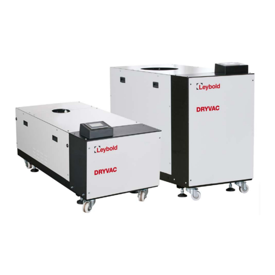
Description DRYVAC DVR 5000-i/S-i/C-i/C-f DRYVAC DV 450-i / 650-i/S-i/C-i DRYVAC DV 1200-i/S-i Fig. 1.1 Pump models Description Design The DRYVAC is a dry compressing vacuum pump. The DRYVAC DV 450 and 650 each have one screw pump stage, the DRYVAC DV 1200 two screw pump stages, the DRYVAC DVR 5000 a Roots and a screw pump stage. - Page 17 2nd pump stage: screw Purge gas pressure setting and condensate vessel Cooling water pressure relief valve Exhaust Optional intake flange (blank flanged) Purge gas module Touchscreen Fig. 1.2 DRYVAC DVR 5000 C-i without side covers 300304403_002_C0 - 11/2016 - © Leybold...
- Page 18 0,01 1000 Einlassdruck mbar Inlet pressure Torr 0,001 0,01 m 3 /h DRYVAC DV 650 C-i Saugvermögen Pumping speed Power consumption Leistungsaufnahme 0,001 0,01 1000 mbar Einlassdruck Inlet pressure Fig. 1.3 Pumping speed curves 300304403_002_C0 - 11/2016 - © Leybold...
- Page 19 Leistungsaufnahme, WH2500 @ 100 Hz Leistungsaufnahme, WH2500 @ 50Hz Power consumption, WH 2500 @ 50 Hz 4000 3500 3000 2500 2000 1500 1000 C-i/C-f 0,0001 0,001 0,01 1000 Inlet pressure Einlassdruck Fig. 1.5 Pumping speed curves 300304403_002_C0 - 11/2016 - © Leybold...
- Page 20 Description DRYVAC DV 450-i / 650-i/S-i/C-i Fig. 1.6 Dimensional drawings, dimensions in mm DRYVAC DV 1200-i/S-i Fig. 1.7 Dimensional drawing, dimensions in mm 300304403_002_C0 - 11/2016 - © Leybold...
-
Page 21: Supplied Equipment
DV 450 / 650 DV 1200 Crane eyes 4x M16 4x M16 (red) for the intake Intake screen Intake screen flange with O-ring with O-ring 300304403_002_C0 - 11/2016 - © Leybold... -
Page 22: Technical Data
32 A/C 32 A/C 63 A/C 50 A/C Short-circuit interrupting capacity < 25 kA < 25 kA < 50 kA < 25 kA Speed Screw / Roots 7,200/min 7,200/min 7,200/min 7,200/6,000/min Min. permissible speed 1,200/min 300304403_002_C0 - 11/2016 - © Leybold... - Page 23 22 slm at max. setting pressure 26 slm ± 10 % Rotor purge gas flow (nozzle d=1.0 mm) at nominal setting pressure 26 slm at max. setting pressure 33 slm 300304403_002_C0 - 11/2016 - © Leybold...
- Page 24 4) bar(g): bar (gauge) is the overpressure, i.e. atmospheric pressure = 0 bar(g) DRYVAC DV 650 and 1200 For DVR 5000 contact Leybold Inlet pressure (mbar) Fig. 1.9 Permissible gas inlet temperature as function of the inlet pressure 300304403_002_C0 - 11/2016 - © Leybold...
-
Page 25: Ordering Information
Purge gas nozzle set for DRYVAC 112 005A30 Permanent inlet purge kit 112 005A32 Crane eyes for DVR 5000 (M20x30; set of 4) 504397V901 GSD file and manual for the Profibus interface see Leybold homepage. 300304403_002_C0 - 11/2016 - © Leybold... -
Page 26: Transport And Storage
Unscrew 8 screws and remove the top covers. Lift the pump at the crane eyes. Use all crane eyes, see Fig. above. The pump can also be transported with a fork lift. Ensure that it cannot tip over. 300304403_002_C0 - 11/2016 - © Leybold... - Page 27 Connect the pump to oper- ate it briefly and then decommission it as described in the following sections. (The intake flange can stay sealed during this brief operation, the exhaust flange must be opened.) 300304403_002_C0 - 11/2016 - © Leybold...
-
Page 28: Installation
Check whether there is any desiccant present in the intake area. If required remove it. Do not block the fan’s cooling air flow. 300304403_002_C0 - 11/2016 - © Leybold... - Page 29 The pumps are supplied filled with synthetic oil or PFPE. Nothing will have to be refilled. Check the oil levels through all oil level glasses (2 per pumping stage). If one of the oil levels is found to be incorrect, please contact us. 300304403_002_C0 - 11/2016 - © Leybold...
-
Page 30: Conforming Use
Pumping of gases and vapours for which the materials of the pump are not ■ suited, consult Leybold. For a list of materials in contact with the process gases, see Section 1.3 Technical Data. Pumping of substances and mixtures (gases, liquids and solids) which are ■... - Page 31 Conversions, manipulations and maintenance work by persons not autho- ■ rised by Leybold. Accessories which have not been specified by Leybold may only be used ■ after approval by Leybold. In the condition as delivered, the DRYVAC DVR 5000 C-i pumps are not ■...
-
Page 32: Pumping 100% Argon
A combination of axial expansion/compression and side displacement is pos- sible. The total percentage of the partial expansions must be less than 100%. For this refer to Fig 3.3. 300304403_002_C0 - 11/2016 - © Leybold... - Page 33 Run the pressure and leak search on the system only after the bellows ■ have been properly mounted. The bellows shall be installed so that an unrestricted visual inspection regarding integrity is possible in regular inter- 300304403_002_C0 - 11/2016 - © Leybold...
-
Page 34: Intake Lines
Abat ement system if required by the process. The DRYVAC pumps will be switched off because of overpressure if the abatement system is too small. Connect the exhaust lines to the pump system’s exhaust connections. Use 300304403_002_C0 - 11/2016 - © Leybold... - Page 35 Run the exhaust line only by way of a fixed installation to the outside and/or connected to a silencer. Check leak tightness of the exhaust lines on a regular basis! DANGER Observe Safety Information 0.4. If your installation requires a housing extraction consult with Leybold. extraction line 300304403_002_C0 - 11/2016 - © Leybold...
-
Page 36: Connecting Cooling Water
A screen has been built into the pressure reducer protecting the valve seat- against coarse contamination, see also Section 5.4 Maintenance. The gauge only serves the purpose of checking the pressure reducer, see Section 5.4.1. 300304403_002_C0 - 11/2016 - © Leybold... - Page 37 (with nitrogen, for example). Pressure relief valve 8 bar(g) Pressure reducer Fig. 3.4 Water pressure reducer Block or label the area of the cooling water and exhaust lines to prevent trip- ping. 300304403_002_C0 - 11/2016 - © Leybold...
-
Page 38: Water Quality
If there is the danger of frost, you may use a water glycol mixture of up to 30 %. DS water can be used for cooling the pump, if the pH value corresponds to the range indicated above. 300304403_002_C0 - 11/2016 - © Leybold... -
Page 39: Connecting Purge Gas
Ensure that the gas flow is not obstructed. The purge gas supply should not be shut off while the pump system is oper- ating, above all especially not during shutdown and venting operations. 300304403_002_C0 - 11/2016 - © Leybold... - Page 40 0.5 bar can be expected. I.e. if the pressure is set to 2.5 bar with closed valves, the pressure switch may signal a fault. In this case set the pressure moderately higher. 300304403_002_C0 - 11/2016 - © Leybold...
- Page 41 PRV Pressure Regulator (Filter) SRV Safety relief valve 8 bar(g) Check valve Opening of these valves will impair the ultimate pressure; see Technical Data. Fig. 3.7 Purge gas and switches schematic for the DVR 5000 300304403_002_C0 - 11/2016 - © Leybold...
-
Page 42: Guidelines For Purge Gas Operation, Settings And Monitoring
Possible purge gases are N and CDA only. The safety always has to be considered (please be careful with air purges and read the safety booklet of Leybold). Exhaust shaft seal purge is running in most of all applications all the time. Rotor purge In most cases not used all the time, often active in specific process steps. - Page 43 2 seconds before pump down and stop the flow when the pres- sure drops below 20 mbar. b) Contamination during chamber vent To avoid contamination during chamber venting, the inlet purge should be ■ activated at all time during the chamber venting. 300304403_002_C0 - 11/2016 - © Leybold...
-
Page 44: Electrical Connection
Section 1.4. Maker: Harting Type: Han K4/2 Ord.No.: 09 38 006 2701 Female insert, 4pole+PE, Type: Han (16B) Ord.No.: 19 30 016 0528 Connector housing for M40 cable fitting (or equivalent type) 300304403_002_C0 - 11/2016 - © Leybold... - Page 45 Connect the potential equalisation conductor as depicted in Fig. 3.9. Copper strap, for example Washer Lock washer Nut M 6 Ground bolt Fig. 3.9 Establishing the potential equalisation at the pump casing 300304403_002_C0 - 11/2016 - © Leybold...
-
Page 46: Leak Search After Installation
Leak Search after Installation Observe Safety Information 0.4. DANGER On delivery, the pump is leak tight to 10 mbar·l/s (integral, leak-checked). Leak-check all relevant connections after having installed the pump. 300304403_002_C0 - 11/2016 - © Leybold... -
Page 47: Operation
GSD file The GSD file and the manual can be downloaded from www.leybold.com/ -> Documents -> Download Software. The GSD file for the i-versions is different from the GSD file for the DRYVAC versions without integrated control. Do not mix them up. - Page 48 The default Profibus address is 40 dec. This address may be changed through the menu displayed through the touch panel of the pump. floating Frame: PE * Request to send signal Fig. 4.1 Pin assignment for the socket 300304403_002_C0 - 11/2016 - © Leybold...
- Page 49 Byte value 0 – 255 = 0 – 100% Valve control Bit 0 All valves closed Bit 1 SV40 open Bit 2 SV40 and SV 42 open Bit 3 SV40, SV41 and SV 42 open 300304403_002_C0 - 11/2016 - © Leybold...
- Page 50 Upper pump actual frequency Upper pump actual current Upper FC temperature Upper pump setpoint frequency Lower pump status Upper pump status Valve status Bit 0 SV40 open Bit 1 SV41 open Bit 2 SV42 open 300304403_002_C0 - 11/2016 - © Leybold...
- Page 51 Pump 2 define setpoint freq. Screw max. = 120 Hz Operating mode selection 0000 0000 = 0 = Mode A 0000 0001 = 1 = Mode B 0000 0010 = 2 = Mode C 300304403_002_C0 - 11/2016 - © Leybold...
- Page 52 Section 4.4.3. Bypass internal system control and control all components individually: In this case we recommend that you consult Leybold as to which NOTICE settings make sense and are permissible. Wrong settings which damage the pump will void the warranty.
- Page 53 Upper pump actual current Housing temperature Lower pump status Bit 0 Ready for operation Bit 3 Error Bit 4 Acceleration Bit 5 Deceleration Bit 10 Normal operation attained Bit 11 Pump is turning Bit 14 Warning 300304403_002_C0 - 11/2016 - © Leybold...
- Page 54 Example for units of measurement Temperature 0001 0111 = 17 hex = 23 °C Frequency 0111 1000 = 78 hex = 120 Hz Current 1010 1010 = AA hex = 170 = 17.0 A 300304403_002_C0 - 11/2016 - © Leybold...
-
Page 55: Start-Up
Check messages on the touchscreen or on the frequency converter display. Setting the Display Language For changing the display language press SETTINGS in the main screen and then on Sprache or Language. Fig. 4.6 Main screen 300304403_002_C0 - 11/2016 - © Leybold... - Page 56 Dry the pump, if required by the process. To do so turn on the pumping sys- tem and run it at ultimate vacuum for a period 60 minutes with a dry nitrogen shaft seal purge before opening it to the process. 300304403_002_C0 - 11/2016 - © Leybold...
- Page 57 At the DRYVAC DVR 5000 the screw pump runs up. After the screw pump has reached 90 % of the max. speed, the Roots pump starts up and acceler- ates to its nominal speed. 300304403_002_C0 - 11/2016 - © Leybold...
- Page 58 Should one of the two pump stages fail due to a malfunction, then the other pump stage is also automatically shutdown. Fig. 4.12 DRYVAC DVR 5000 ready for operation 300304403_002_C0 - 11/2016 - © Leybold...
-
Page 59: The Display Icons
Pump/process was started (Start command is present) Valve is open, gas flow is possible Valve is closed, no gas flow is possible Process “ Ready” has been reached, normal equipment status Pressure sensor Vacuum gauge head 300304403_002_C0 - 11/2016 - © Leybold... -
Page 60: Operation
PROCESS CONFIGURATION LISTS SETTINGS PASSWORD The corresponding submenu items are: PROCESS Process Logging Temperatures Pump data CONFIGURATION Process Wizard Service mode LISTS Alarm/warning SETTINGS Time & Date Network Screensaver Language Info PASSWORD Password level entry 300304403_002_C0 - 11/2016 - © Leybold... -
Page 61: Password Handling
“Servicemode”. “Wizard” cannot be accessed at the DRYVAC. To activate the Password level input, press the key icon. Fig. 4.15 Password input The up coming window shows the actual User Level (0 = no login) 300304403_002_C0 - 11/2016 - © Leybold... - Page 62 “customizing” is the password for level 1 (the password is fixed at the moment) to activate all functions of the touchscreen. The level 1 password can be deactivated while pressing the “Log-out” button or switch OFF the mains supply. Fig. 4.17 Password input 300304403_002_C0 - 11/2016 - © Leybold...
-
Page 63: Setting Pump Configurations
Under Configuration pressing on Process and then on Designer opens a menu for setting up the valves for certain operating conditions. Fig. 4.19 System parameters We recommend to consult with Leybold which pump configuration is sen- NOTICE sible and permissible for your process. Wrong configurations, which may damage the pump, will nullify the warranty. - Page 64 Fig. 4.20 System parameters limits Moreover here the Profibus address can be entered (default = 40) and a new, detailed Profibus telegram can be selected, for telegram descriptions see Section 4.2. Fig. 4.21 System parameters limits 300304403_002_C0 - 11/2016 - © Leybold...
-
Page 65: Warning And Shut-Off Thresholds
(Pressure difference to 50 mbar ambient pressure) Purge gas supply pressure – 2.4 bar(g)* (optional) Pump housing internal 50 °C – temperature * selectable at the display if evaluated as warning or as fault 300304403_002_C0 - 11/2016 - © Leybold... -
Page 66: Failure List
Through the buttons - and + move to the in each case next five error messages. Further to the right in the list, a description of the errors can be found. For a list of error messages please refer to Section 6. 300304403_002_C0 - 11/2016 - © Leybold... - Page 67 Operation Fig. 4.24 Failure list: Description 300304403_002_C0 - 11/2016 - © Leybold...
-
Page 68: Logging
The red cursor line can be moved in the graphic display to the left and to the right and will then indicate the values measured at the selected point of time. Fig. 4.26 Logging 300304403_002_C0 - 11/2016 - © Leybold... - Page 69 Fig. 4.28 Logging: channel settings The 4 measurement channels can be renamed and the colour assignment can be changed. Moreover, the graphic display can be scaled. Changes in this menu will not affect the recorded measured values. 300304403_002_C0 - 11/2016 - © Leybold...
-
Page 70: Settings
Operation 4.4.7 Settings Time & Date Fig. 4.29 SETTINGS > Time & Date Network Fig. 4.30 SETTINGS > Network 300304403_002_C0 - 11/2016 - © Leybold... - Page 71 “RESTART MACHINE” and the green system LED on the front panel will flash. Now switch the mains power off, remove the memory stick and switch on again. Thereafter this system should boot up again. 300304403_002_C0 - 11/2016 - © Leybold...
- Page 72 “1” to “4” in the correct sequence. The displayed measured values are updated when “Screen lock“ is run- ning. Fig. 4.33 Unlock screensaver 300304403_002_C0 - 11/2016 - © Leybold...
-
Page 73: Shut-Off And Venting
If during longer downtimes the system shall remain conditioned for a rapid pumpdown, we recommend to vent in the system with dry nitrogen to atmo- spheric pressure and maintain it in this condition without opening it. 300304403_002_C0 - 11/2016 - © Leybold... -
Page 74: Removing From Service
Blow out the cooling water coils with compressed air or Nitrogen (max. 4 bar). Blow into the cooling water inlet port only. Also when storing the pump for longer periods of time the lubricant remains in the pump. 300304403_002_C0 - 11/2016 - © Leybold... -
Page 75: Maintenance
Instructions: “Declaration of Contamination for Compressors, Vacuum Pumps and Components”. Another suitable form is available from www.leybold.com/ -> Documents -> Download Documents. Attach the form to each pump. This statement detailing the type of contamination is required to satisfy legal requirements and for the protection of our employees. -
Page 76: Exchanging The Lubricant
Fill in new oil at a pump temperature of 15 ºC to 25 ºC. For this use a clean funnel. Make sure to use the right kind of oil. Only use Leybold oil. Please consult us if you intend to run the pump with other oils or special lubricants. - Page 77 Maintenance Remove top covers Oil level glass Oil fill plug Oil drain plug max. 0 mm min. – 4 mm Oil level with the pump at standstill Fig. 5.1 Oil change DRYVAC DV 5000-i 300304403_002_C0 - 11/2016 - © Leybold...
-
Page 78: Cleaning The Filter Insert In The Cooling Water Pressure Reducer
Clean the filter insert with plain cold water. Screw the cartridge (thread: 39x1.5) back in, tightening torque 20 Nm. Open the water supply and discharge again, check leak tightness and pres- sure setting. 300304403_002_C0 - 11/2016 - © Leybold... -
Page 79: Replacing The Filter Cartridge In The Purge Gas Pressure Reducer
See Fig. 3.5. For replacing, unscrew the metal protection basket with cup from the pres- sure reducer. Unscrew the mounting component and detach the used filter cartridge. Fit the parts using a new filter cartridge again. 300304403_002_C0 - 11/2016 - © Leybold... -
Page 80: Fuse Replacement
Moreover, also make sure that the pump can- not start up once the side panel cover is open. 300304403_002_C0 - 11/2016 - © Leybold... -
Page 81: Troubleshooting
Surge voltage entering from the mains supply voltage. Mains supply voltage is too high. Check the mains supply voltage. Heatsink Cooling water temperature is too high. Check the cooling water condition Overheat Internal cooling fan is stopped. Leybold Service (oH) 300304403_002_C0 - 11/2016 - © Leybold... - Page 82 (PF) There is excessive fluctuation in the mains vol- Correct the wiring. tage. There is poor balance between voltage phases. Stabilize drive input power. Leybold Service The main circuit capacitors are worn. Output Phase Frequency converter fault Leybold Service Loss (LF)
- Page 83 (including oFx) Output Current Leybold Service Imbalance (LF2) Pullout Detection Check wiring. If no error is detected contact (Sto) Leybold Service. PG Disconnected Check wiring. If no error is detected contact (PGo) Leybold Service. 300304403_002_C0 - 11/2016 - © Leybold...
- Page 84 Internal faults. Switch DRYVAC off, check installed options and options switch DRYVAC on again. If the fault is still dis- played contact Leybold Service and state the fault number and displayed text. 300304403_002_C0 - 11/2016 - © Leybold...
-
Page 85: Alarm Messages Of A Pump Stage
Check link between SC and S6. The frequency converter does not accept Run commands. External Fault, Check wiring. Input Terminal S3 (EF3)/ S4 (EF4)/ S5 (EF5)/ S6 (EF6) 300304403_002_C0 - 11/2016 - © Leybold... - Page 86 When the pump is running the control does Command Input not accept a motor reverse command. During Run (rUn) Serial Commu- Check wiring. If no error is detected contact nication Trans- Leybold Service. mission Error (CALL) 300304403_002_C0 - 11/2016 - © Leybold...
- Page 87 Lubricant level is too high. Drain lubricant down to the correct level. Lubricant level is too low. Top up lubricant to the correct level. Wrong lubricant filled in. Leybold service Bearing is defective. Leybold Service. 300304403_002_C0 - 11/2016 - © Leybold...
- Page 88 “Forerunner” for Alarm 186. Waiting time until during delay of alarm 186 is displayed. MFDI set in S2 C-Lim Alarm Drive was running at or above the Final Leybold Service Current Limit for a too long time. 300304403_002_C0 - 11/2016 - © Leybold...
-
Page 89: Alarm And Fault Messages Dryvac
Value too low Alarm Housing Ambient temperature > 40°C Check pump ambient temperature. temperature: Cooling water temperature too high Check cooling water temperature and flow. Value too high Mains voltage too high Check mains voltage. 300304403_002_C0 - 11/2016 - © Leybold... -
Page 90: Pump Malfunctions
Rotor is running untrue. Leybold Service, shutdown pump immediately. Oil slinger disc makes contact with the gear housing Leybold Service. or the oil pipe. Oil pump is blocked or defective. Leybold Service, shutdown pump immediately. 300304403_002_C0 - 11/2016 - © Leybold... - Page 91 Leybold Service. Motor incorrectly connected. speed. Leybold Service. Motor stator defective. Detect leak and seal it. Leybold Service. Motor rotor defective. Leybold Service. Vacuum pump system has a gas leak. Impeller play is too great. Bearing defective.
- Page 92 Fuse F4 defective (LED lights). Replace fuse 0.5 A (slow blow). (option) doesn’t Circuit breaker F1 has tripped. Leybold Service work. Fan doesn’t work Circuit breaker F1 has tripped. Leybold Service Fan defective Leybold Service 300304403_002_C0 - 11/2016 - © Leybold...
-
Page 93: Wearing Parts
Waste oil from vacuum pumps must not be mixed with other substances or materials. Waste oil from vacuum pumps (Leybold oils which are based on mineral oils) which are subject to normal wear and which are contaminated due to the influence of oxygen in the air, high temperatures or mechanical wear must be disposed of through the locally available waste oil disposal system. -
Page 94: Ec Declaration Of Conformity
Wearing Parts / Disposal EC Declaration of Conformity 300304403_002_C0 - 11/2016 - © Leybold... -
Page 95: Certificates
Laboratory” (NRTL) for the USA and Canada. This product has been certified to the requirements of CAN/CSA-C22.2 No. 61010-1-12, or a later version of the same standard incorporating the same level of test- ing requirements. 300304403_002_C0 - 11/2016 - © Leybold... - Page 96 Person to contact: Calibration: Factory-calibr. Phone : Fax: Quality test certificate DIN 55350-18-4.2.1 End user: A. Description of the Leybold product: Failure description: Material description : Catalog number: Additional parts: Serial number: Application-Tool: Type of oil (ForeVacuum-Pumps) : Application- Process: B.
-
Page 97: Index
Feet 8, 14, 15, 16, 25, 26, 27 Fluorine 17, 23, 43, 87 Frequency converter 76, 78, 81 Venting 69 Fuse 74, 86 Vibration 31, 32 Gas ballast 11, 15, 19, 22 Gauge 38 Grounding 27, 41 GSD file 24, 43 300304403_002_C0 - 11/2016 - © Leybold... - Page 98 Sales and Service Germany America Great Britain Leybold Japan Co., Ltd. Tsukuba Technical Service Center 1959, Kami-yokoba Leybold UK LTD. Leybold GmbH Tsukuba-shi, Ibaraki-shi 305-0854 Unit 9 Sales, Service, Support Center (3SC) Japan Silverglade Business Park Leybold USA Inc. Bonner Strasse 498...
Need help?
Do you have a question about the DRYVAC DV 450-i and is the answer not in the manual?
Questions and answers