
Related Manuals for LEYBOLD Turbovac TW 70 H


Summary of Contents for LEYBOLD Turbovac TW 70 H
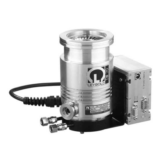
- Page 1 LEYBOLD VACUUM Vacuum Solutions Application Support Service GA 05.145/3.02 TURBOVAC TW 70 H Wide-Range Turbomolecular Pump with Integrated or External Frequency Converter Operating Instructions...
-
Page 2: Table Of Contents
110°C (230 °F). Ignition sparks 4.2 Service by LEYBOLD ....30 could occur in case of damage to the pump and these could ignite explosive mixtures. -
Page 3: Design
Rotor Holweck stage Motor Bearing Forevacuum connection Fig. 1 Section through a TURBOVAC TW 70 H 1.1 Design The pump connection cable is fixed and ready to connect to the TURBO.DRIVE S frequency converter. The pumps comprise essentially the pump housing, a multi-stage rotor with the stator group, and the drive. -
Page 4: Ordering Data
1.3 Ordering data 1.3.1 Pumps 8 0 0 0 0 2 V Catalog Number TURBOVAC TW 70 H H i gh - v a c u u m f l an g e a n d h o using DN 63 ISO-K... - Page 5 Description 1.3.2 Frequency converter and accessories for the frequency converter Frequency converter TURBO.DRIVE S Part No. Basic unit 800070V0001 with RS 232 interface 800070V0002 D ri with RS 232 interface and mounted heat sink 800070V0005 S IN with RS 485 interface 800070V0003 with RS 485 interface and mounted heat sink 800070V0006...
- Page 6 Description 1.3.3 Accessories for the pump Part No. Splinter guard fine 200 17 170 Camozzi coupling 200 04 361 Water cooling with connection G 1/8” 800135V0001 (for fitting to pumps without forced cooling) Adapter G 1/8” - 1/4” Swagelok Tube connector G 1/8“ outer dia. 10 mm 200 18 366 Tube connector G 1/8“...
-
Page 7: Technical Data
Description 1.4 Technical data 1.4.1 TURBOVAC TW 70 H ————————————————————————————————————————————————————————— High-vacuum connection DN 63 ISO-K / DN 63 CF DN 40 KF / DN 40 CF Pumping speed (without splinter guard)for 65 l·s 55 l·s Ultimate pressure with two-stage, oil-sealed rotary vane pump <... - Page 8 Description Ø 95 Ø 95 26° 26° 2° 26° 26° Catalog Number 800002V1234 Catalog Number 800002V1934 TW 70 H TW 70 H with DN 63 ISO-K flange, air cooling, with DN 63 ISO-K flange, no forced cooling, DN 16 KF forevacuum connection, DN 16 KF forevacuum connection, without frequency converter without frequency converter...
- Page 9 Description Ø 95 DN 63 ISO-K 155.5 50.5 Catalog Number 800002V1235 TW 70 H with DN 63 ISO-K flange, air cooling, DN 16 KF forevacuum connection, with frequency converter 2° 26° Ø 95 Ø 95 Cable length 152.5 400 mm 2°...
- Page 10 Description 1.4.2 TURBO.DRIVE S 1.4.3 Power supply SITOP Power 10 Supply voltage 24 V DC ± 5% AC input voltage 120/230 V, 50/60 Hz Residual ripple < 2% Tolerance 93 - 132 V Max. power consumption 170 W 187 - 264 V Max.
- Page 11 Description DRIVE (X3) 24 V DC (X4) HEAT SINK HEAT SINK 23,5 RS485 (X5) TURBO.DRIVE S ERROR POWER STATUS REMOTE (X1) HEAT SINK HEAT SINK 18,1 63,8 Fig. 4 Dimensional drawing for the TURBO.DRIVE S with RS 485 interface and the SITOP Power 10, dimensions in mm GA 05.145/3.02 - 02/2001...
-
Page 12: Connections
Connections 2 Connections 2.1 Operating environment Caution The pumps are not suitable for pumping The maximum permissible ambient temperature is 45 °C aggressive or corrosive media or those (113 °F). Do not expose the pump or the frequency con- which contain dust. verter to dripping or spraying water Install a micropore filter when pumping If the pump is used within a magnetic field, the magnetic... -
Page 13: Attach The Pump To The Vacuum Chamber
Connections High-vacuum connection flange Connection cable to TURBO.DRIVE Forevacuum connection Fig. 5 Connection elements 2.2 Attach the pump to the No support is required. If nonetheless an additional fastening is requested you can use the 3 boreholes in vacuum chamber the pump’s bottom. - Page 14 A collar flange with circlip and the appropriate gasket may be used to connect the pump. A collar flange is required when using ultra-vacuum sea- ling gaskets. The order numbers for the flange components are given in the Leybold Catalog. GA 05.145/3.02 - 02/2001...
-
Page 15: Forevacuum Connection
Connections Fig. 8 Forevacuum connection with Camozzi coupling 2.3 Forevacuum connection Figure 13 is a schematic diagram of a pump system incorporating a turbomolecular pump and a TRIVAC forevacuum pump with an anti-suckback valve. The high vacuum pressure level which can be achieved is a function of the volume of gas flow Q to be pumped A separate safety valve must be provided for oil-sealed and the forevacuum pressure. - Page 16 Connections Cooling water connnections Fig. 9 Pump with water cooling °C Cooling water temperature Fig. 10 Cooling water requirements GA 05.145/3.02 - 02/2001...
-
Page 17: Connect The Cooling
(= 3.57 mmol/l) The pump must be operated with the air Further information on request. cooling unless you have an agreement from Leybold for different operation. Connecting the cooling water Screw on the cooling water lines; connections G 1/8”. Air cooling... - Page 18 Connections Fig.12 Pump with air cooling Legend for Fig. 13 1 Turbomolecular pump 2 Forevacuum gauge port 3 Forevacuum pump 4 Resonance damper 5 Adsorption trap 6 Forevacuum valve 7 High-vacuum valve 8 Valve in the roughing pump line 9 Frequency converter —...
- Page 19 Connections TURBOVAC with integrated frequency converter without forced cooling Mains Power supply 24 V DC cable, max. 20 m TURBOVAC with integrated frequency converter with water cooling 24 V DC cable, max. 20 m Mains Power supply Mains Power supply DC cable, Cooler optional with shielding,...
-
Page 20: Electrical Connection
Fig. 15 TURBO.DRIVE S 2.6 Electrical connection Hexagon threaded bolt The TURBO.DRIVE S frequency converter needed to operate the TURBOVAC TW 70 H has either been inte- grated in the pump or is a separate unit. For connection examples see Fig. 14. Warning... - Page 21 The frequency converter has an internal SMD fuse T 10 Connect the frequency converter to the 24 V DC power A. It can only be changed by the Leybold Service. supply at the DC connector X4; see Fig. 19. Caution Ensure correct polarity.
- Page 22 Connections REMOTE (RS 485 / 232) 93 - 132 / DRIVE (X3) 187 - 264 V AC, 24 V DC (X4) 50/60 Hz HEAT SINK HEAT SINK 24 V DC Optional jumper for 120 V operating voltage range 93 - 132 V + 24 V DC 0 V DC LED POWER...
- Page 23 0,5 A, 24 V DC to 15. Addresses over 15 are not supported. For more detailed information concerning the USS pro- tocol please contact Leybold. TxD/RxD + TxD/RxD – The RS 485 bus should be connected as shown in Fig.
- Page 24 Connections + 5 V 390 Ω Links for activation of the bus terminator Bus terminator 150 Ω 150 Ω TxD/RxD – 82 Ω TxD/RxD + 390 Ω TURBO.DRIVE X5 (7) X5 (8) X5 (7) X5 (8) TURBO. TURBO. Master DRIVE DRIVE Fig.
- Page 25 Connections Designation Range Unit Default Format Description Max value setting for motor current 5 ... 75 0,1 A Maximum permissible motor current Nominal pump frequency 750...1200 1200 Highest permissible frequency Minimum setpoint frequency for the pump 375..600 Lowest permissible frequency Minimum frequency When the pump is accelerating this level...
- Page 26 Connections Designation Range Unit Default Format Description Converter operating 0...19 Totals the operating hours for the converter hours counter Years 0,01h when the pump’s drive is active Pump status word Meaning of the bits: Bit 0 Normal operation = 1 Bit 1 Ready for switch on = 2 Bit 2 Speed is increasing = 4 Bit 3 Speed is dropping = 8...
-
Page 27: Operation
3 Operation For the power supply units offered or recommended by Warning Leybold: If the contacts 7 and 8 at the REMOTE (X1) The turbomolecular pump must only be connector are closed the pump starts automatically operated in the proper condition and under... -
Page 28: Shutting Down
3.3 Venting • for the power supply units offered or recommended by Leybold switch off the DC voltage. When using oil-sealed forevacuum pumps, vent the pump each time it is shut down to prevent possible return Switch off the forevacuum pump. -
Page 29: Bakeout
Pack the pump so that it cannot be damaged during shipping and storage. Pay particular attention to protec- tion for the flanges and the electrical plug. Observe the instructions in Section 4.2 if you forward the pump to Leybold. GA 05.145/3.02 - 02/2001... -
Page 30: Maintenance
If required clean the turbomolecular pump of dust with a dry cloth. 4.2 Service by LEYBOLD Whenever you send a pump to Leybold, indicate whether the pump is contaminated or is free of sub- stances which could pose a health hazard. If it is conta- minated, specify exactly which substances are involved. -
Page 31: Troubleshooting
Troubleshooting 5 Troubleshooting Warning When the connector cable is attached, the outputs at the frequency converter are not free of voltage. Before you start searching for the source of the problem, you should carry out a few simple checks: Are the connections in good working order? •... - Page 32 Bearing defective. Have the pump repaired (may be done only by a Leybold service technician). Red ERROR LED is on: Forevacuum pressure too high. Check the forevacuum pump and use a Error code 3 + 7: bearing tem- different forevacuum pump if necessary.
- Page 33 Yellow power LED is not on. No DC power Check cables and power supply. Internal SMD fuse has blown Inform Leybold Service. The following may cause a blown SMD fuse: • DC power miswired • Disconnection of the DC cable while the pump was still rotating •...
-
Page 34: Ec Declarations
EEC Manufacturer’s Declaration in the sense of EEC Directive on Machinery 89/392/EWG, Annex IIb We - LEYBOLD Vacuum GmbH - herewith declare that Applied harmonized standards: operation of the incomplete machine defined below, is • EN 292 Part 1 & 2 Nov. - Page 35 Declaration of Conformity as defined by the EMC guideline 89/336/EWG with revisions 91/263/EWG and 93/68/EWG RIR-TDS2-EMV Product: TURBO.DRIVE S 2000-12-07 We herewith declare sole responsibility for the product meet the requirements outlined in the EG requirements on 89/336/ EWG (EMC guideline) with revisions 91/263/EWG and 1.
- Page 36 Declaration of Conformity as per EG Low-Voltage Guidelines 73/23/EWG, Attachment lll B RIR-TDS2-NSR Product: TURBO.DRIVE S 2000-12-07 We herewith declare sole responsibility for the product including the required accessories, as agreeing with EG guide- lines 72/23/EWG, and 93/68/EWG. 1. Product: Inverter 2.
- Page 37 Declaration of Contamination of Vacuum Equipment and Components The repair and/or service of vacuum equipment and components will only be carried out if a correctly completed declaration has been submitted. Non-completion will result in delay. The manufacturer could refuse to accept any equipment without a declara- tion.
- Page 38 LEYBOLD VAKUUM GmbH Bonner Strasse 498 (Bayenthal) D-50968 Cologne Tel.: + 49 221 347-0 Fax: + 49 221 347-1250 http://www.leyboldvac.de e-mail:documentation@leyboldvac.de...
Need help?
Do you have a question about the Turbovac TW 70 H and is the answer not in the manual?
Questions and answers