
Related Manuals for Minebea Intec CAS-SPC Series


Summary of Contents for Minebea Intec CAS-SPC Series
- Page 1 Operating Instructions Minebea Intec Combics Series Complete Scales Models CAW3P | CAW3S | CAS3E | CAS3G |CAS...-SPC... 98648-018-49...
-
Page 2: Table Of Contents
Scale Configuration Balance Dimensions Service Mode Accessories Entering Adjustment and Linearization Weights Documents List Function Allocation of the Allocation for the J Key Minebea Intec Services for Calibration/Adjustment Declaration of Conformity External Adjustment EU-type examination certificate Internal Calibration Test Certificate... -
Page 3: Notes On Using This Manual
This manual is part of the product. Keep it in a safe and easily accessible location. If the manual should be lost or misplaced, please contact Minebea Intec for a replacement or download the latest manual from our website: www.minebea-intec.com... -
Page 4: Warnings And Safety Precautions
The operator shall be responsible for any modifications to the equipment and for any connections of cables or equipment not supplied by Minebea Intec and must check and, if necessary, correct these modifications and connections. - Page 5 Conformity with the list of permitted weighing ranges. – A sticker with the “Minebea Intec“ logo was affixed to the indicator as a control seal following verification. This seal will be irreparably damaged if you attempt to remove it. This will nullify the verification‘s validity. In this case, re-verification would be required in compliance with all relevant national regulations and laws.
-
Page 6: Device Description
Device Description Device Description Combics complete scales: – Are robust and durable – Are easy to clean and disinfect – Are easy to operate, thanks to the following features: – Large, backlit, fully graphical dot-matrix display – Large keys with positive click action –... -
Page 7: Overview Of Equipment
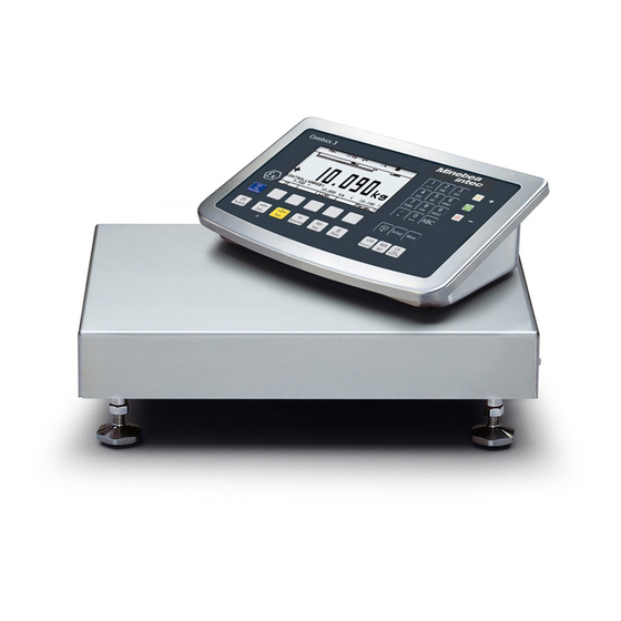
Device Description General View of the Equipment Platform 1 Level indicator 2 Load plate 3 Leveling feet Indicator 4 10 digit keypad for entering alphanumeric values 5 LEDs (for checkweighing and classification) 6 Display (for details, see “Operating Design“ chapter) 7 Additional function keys (see “Operating Design“) 8 General function keys: Zero, Tare, Switch function, Adjustment/ Calibration, Print/Data output... -
Page 8: Installation
Installation Installation When a Combics indicator is ordered with special equipment, the desired options come pre-loaded from the factory. Storage and Shipping Conditions Once the equipment has been removed from the packaging, it may lose accuracy if subjected to strong vibration. If the load plate is lifted using a vacuum lifting pad, gloves, safety shoes and safety gear must be worn. - Page 9 Installation CAS3-G models (IGG): Remove transport locks Place the weighing platform at its installation location, remove the weigh- ing pan. Remove the transport lock: Remove screw 1 Loosen screw 2. Turn the mounting bracket 180° and re-secure screw 2. Re-attach screw 1 to the lever CAS3-G models (FEG): Remove transport locks Set up the weighing platform in the vicinity of your work area, remove the load plate (1), and remove the red plastic caps.
- Page 10 Installation Weighing Platform, Leveling (IGG) Align the weighing platform leveling feet so that air bubble is centered within the circle of the level indicator. Check to ensure that all four leveling feet rest securely on the work surface. y Each of the leveling feet must support an equal load. Re-fasten the lock nuts after leveling: Small platforms (1 measuring cell) counter to the platform frame, large platforms (4 measuring cells) counter to the platform foot.
- Page 11 Installation Shock Resistance The weighing platform has a robust design; however, falling weighing samples, side impacts and shocks should be avoided. The weighing platform can withstand loads specified in the DIN standard IEC68 Part 2-27. Notes on Planning Superstructures Superstructures must be completely attached before the weighing platform is connected to the power.
-
Page 12: Getting Started
5.) Carry out an alignment: for adjustment, see page 27, for linearization see page 24 Connecting Peripheral Devices or Another Weighing Platform An analog Minebea Intec IS weighing platform is connected at the factory to the Combics indicator WP1 input. The load cell should be connected by a certified technician who has received specialized training from Minebea Intec. -
Page 13: Connecting An Is Weighing Platform To A Combics 3
After you close the housing again, use a pressure gauge to check the integrity of the IP69K protection. For details, contact the Minebea Intec Service Center. Connecting Cables Insert all cable wires through the ferrite case, wind them around the ferrite case and then reinsert back through the ferrite case. -
Page 14: Connecting Peripheral Devices Or A 2Nd Weighing
Getting Started Connecting Peripheral Devices or a 2nd Weighing Platform: Combics 3 Digital PCB PS2 COM1 COM2 COM1, COM2 and PS2 terminal assignments (applies to all PCBs) Weighing platform Interface 2 LOAD_PRINTER 11 Clear to send (CTS) 21 5 V switched RESET_OUT 12 Data terminal ready (DTR) 22 PS/2_data... -
Page 15: Interface Pin Assignment Chart Com1
Getting Started Interface PCB for RS-232/485 for IS weighing platform PS2 COM1 COM2 A62/72 (option A62/A72) Weighing platform Interface 1 Interface PCB A6/7 and A62/72 11 TxD/RxD+ 12 TxD/RxD- 13 LINE_OUT 14 LINE_OUT 15 GND Adjustment Lock 16 GND Keys LED + Display Keypad LED + Display , A Alibi memory... -
Page 16: Connecting A Pc Via Interface Com1
Getting Started Connecting a PC via Interface COM1 Use the following cables to connect a PC to the indicator in accordance with the RS-232C/V24 standard (max. cable length 15 m): Model type CAW3P | CASLE-SPC: connecting cable 7357312 Model type CAW3S | CAS3: connecting cable YCC02-D09F6 RS232 Pin assignment... -
Page 17: Interface Pin Assignment Chart Com2
Getting Started Interface Pin Assignment Chart COM2 Model type CAW*P | CASLE-SPC (IP-44 protection) COM2 female connectors: 9-pin D-Submini female connector (DB9S) with screw lock hardware for cable gland Recommended interface connector: 9-pin D-Submini (DB9) with shielded cable clamp assembly and shield plate and fas- tening screws (Amp type 164868-1) Pin assignment: +5 V out... -
Page 18: Connecting A Pc Via Interface Com2
Getting Started Connecting a PC via Interface COM2 Use the following cables to connect a PC to the indicator in accordance with the RS-232C/V24 standard (max. cable length 15 m): Model type CAW3P | CASLE-SPC: connecting cable 7357312 Model type CAW3S | CAS3: connecting cable YCC02-D09F6 RS232 Pin assignment... -
Page 19: Interface Pin Assignment Chart Ps2
Getting Started Interface Pin Assignment Chart PS2 Model type CAW3P | CASLE-SPC (IP44 protection) PS2 female connector: 6-pin miniature socket PS2 (Mini-DIN) Recommended interface connector: 6-pin miniature socket PS2 with integrated shielded cable clamp assembly Pin assignment: Pin 1: Keyboard data (data interface cable) Pin 2: Not assigned Pin 3:... - Page 20 The printed voltage rating (see type label) must match the voltage in the place of installation. If the voltage specified on the label or the plug design of the AC adapter do not match the rating or standard you use, please contact your Minebea Intec office or dealer.
-
Page 21: Scale Configuration
Configuring Weighing Platforms Configuring Weighing Platforms Service-Mode Purpose The Service mode enables access to additional menu items in the Setup menu which are not displayed when the Service mode is not active. The most important calibration and adjustment work for the indicator and for the connected weighing platform can be carried out in the Service menu. - Page 22 Save parameters o No ) Equipment version: – then blocked internally ) Not available on devices verified for use in legal metrology ) Only when operated with Minebea Intec IS weighing platforms or an external ADC Operating Instructions Combics Complete Scales...
- Page 23 Configuring Weighing Platforms Device Parameters IS-485 Calibration/Adjustment unit Grams /g Kilograms /kg Tons /t o Pounds /lb Menu items “Adapt filter“ - “Factory settings: only bal. func,“ see the “Setup Overview (Parameters)“ section COM-1 (when the WP is assigned to this interface) COM-2 (when the WP is assigned to this interface) UNICOM (only if available) WP2, see the “Setup Overview (Parameters)“...
- Page 24 Configuring Weighing Platforms Setup Menu for A/D Converter Configuration Setup access in Service mode WP1 – Internal – ADC configuration Standard configuration Ranges Single-range mode Scale interval d Max. cap. Multi-interval mode Scale interval d Range 1 Range 2 Range 3 Max.
- Page 25 Configuring Weighing Platforms Analog/Digital Converter (ADC) Purpose Adjust the parameters of the analog/digital converter to the connected load cell or weighing platform. After ADC configuration, the ADC in connection with the load sensor is defined as a scale. Once the ADC configuration has been locked, the indicator can no longer be used to influence weighing results.
- Page 26 Configuring Weighing Platforms Select the desired configuration using the “ “ or “ “ soft key. Confirm your selection using the “ “ key. Make additional settings in the submenu: scale interval d/verification scale interval e, minimum load (Verifiable configuration only), range limits (Multi-interval or Multiple range mode only) and maximum capacity.
- Page 27 Configuring Weighing Platforms Analog/Digital Converter (ADC) Configuration Condition The weighing platform must already be connected. Open the Menu Access Switch The menu access switch is located on the back of the indicator right next to the weighing platform connection. Remove the cap. Slide the switch to the left (= “open“...
- Page 28 Configuring Weighing Platforms In the example shown here, “ “ has been selected Single range mode (marked by “ “). To select a different weighing range configuration, use the “ “ or “ “ soft key to select the corresponding line and open the selected menu using the “ “...
- Page 29 Configuring Weighing Platforms Multi-interval Mode The illustration shows an example of the input menu opened for multi-interval mode range configuration. This example shows the parameters for a scale in “Verifiable” configuration, with 2 weighing ranges and a maximum capacity of 6.000 kg.
- Page 30 Configuring Weighing Platforms To change the calibration/adjustment unit, select the unit using the “ “ or “ “ soft key and confirm using the “ “ soft key. Use the “ “ soft key to go back to the “ “...
- Page 31 Configuring Weighing Platforms The displays depicted in the next two illustrations on the left show data from a multi-interval scale configured as described above, or a similarly configured multiple-range scale. If the A/D converter was configured with a “Verifiable” data record, the lines for display of metrological data (lines 1 and 2) show the data valid for use in legal metrology.
-
Page 32: Entering Adjustment And Linearization Weights
Configuring Weighing Platforms Entering Geographical Data for Use in Legal Metrology Purpose Entering geographical data allows the external adjustment of weighing equipment at a place (e.g. at the manufacturer or vendor‘s place of business) that is not the same as the place of installation. If the weighing equipment is adjusted at the place of installation, it is not necessary to enter geographical data. - Page 33 Configuring Weighing Platforms Procedure Remove the cap. Slide the menu access switch to the left (= “open“ position). If the device is part of a verified weighing facility, this will only be possible if the verification seal is broken. The weighing equipment must then be verified again.
- Page 34 Configuring Weighing Platforms Entering Gravity Use the “ “ or “ “ soft key to select the corresponding input field. Enter gravity in m/s via the keypad and confirm using the “ “ soft key. Permissible value range: d < gravity 2 d < 9.700000 9.900000 In the example shown here, the value for gravity has been changed.
- Page 35 Configuring Weighing Platforms Press J to start an external adjustment. The display “ “ appears briefly. C.EXT.D In the example, the altitude and latitude of the installation location are being entered. C.EXT.D C.EXT.DEF. The display “ Altitud “ appears briefly. Altitud C.EXT.DEF.
- Page 36 Configuring Weighing Platforms If gravity is being entered instead of altitude and latitude, then “Gravity“ is displayed for a brief time after “CAL.“ The entered value appears in m/s , here for the “Germany (Zone D)“ setting. Press J to confirm the displayed value or press ( to cancel the adjustment. y You are prompted to place the required weight on the platform (e.g.: 5.0 kg).
- Page 37 Configuring Weighing Platforms Entering Adjustment and Linearization Weights Purpose Entering adjustment and linearization weights. Procedure See also “Calibration and Adjustment“ in the chapter called “Operation“. Remove the cap. Slide the menu access switch to the left (= “open“ position). Activate the Service mode, see “Service Mode.“ Select weighing platform “...
-
Page 38: Function Allocation Of The Allocation For The J Key For Calibration/Adjustment
Configuring Weighing Platforms Function Allocation of the allocation for the Key for Calibration/Adjustment The J key is used for the calibration/adjustment function. Key settings can be Purpose changed when the Service mode is activated: Procedure Remove the cap. Slide the menu access switch to the left (= “open“ position). Activate the Service mode, see “Service Mode.“... -
Page 39: External Adjustment
Configuring Weighing Platforms Use the “ “ soft key to open the “ menu. CAL key function y The “ “ submenu is displayed. CAL key function Use the “ “ or “ “ soft key to select the corresponding menu item and confirm with “... - Page 40 Configuring Weighing Platforms Press e to turn off the device. Press e turn the device back on. y The Minebea Intec logo is displayed briefly, after which the device is in normal weighing mode. Press ( to unload and zero the scale.
- Page 41 Press e to turn off the device. -------------------- Press e turn the device back on. Ext. Calibration y The Minebea Intec logo is displayed briefly, after which the device is in normal 5000 g weighing mode. Diff. + 10 g Ext.
- Page 42 Configuring Weighing Platforms Press e to turn off the device. Press e turn the device back on. y The Minebea Intec logo is displayed briefly, after which the device is in normal weighing mode. Press ( to unload and zero the scale.
-
Page 43: Internal Calibration
Configuring Weighing Platforms If a serious operator error should occur during calibration (for example, if the menu setting “ “ is active and the wrong calibration Cal. then auto adj. weight is placed on the scale), the scale might completely fail to stabilize, which means it cannot show a zero point. - Page 44 Configuring Weighing Platforms Procedure Remove the cap. Slide the menu access switch to the left (= “open“ position). Activate the Service mode, see “Service Mode.“ Select weighing platform “ “ in the “ “ WP 1 Device Parameters menu item. If the “...
- Page 45 Configuring Weighing Platforms If the weighing platform has multiple load cells, multiply the nominal capacity accordingly. Example: The weighing platform has 4 load cells each at 50 kg. The nominal capacity is 4 x 50 kg = 200 kg. In the example shown here, the weighing platform consists of one load cell with a maximum capacity of 10 kg.
-
Page 46: Function Allocation Of The J Key For Linearization And Setting/Deleting The Preload
Configuring Weighing Platforms Function Allocation of the J Key for Linearization and Setting/ Deleting the Preload The J key is normally used for the calibration/adjustment function. Purpose The following additional functions can be allocated to the key when the Service mode is activated: –... -
Page 47: External Linearization
Configuring Weighing Platforms External Linearization with the Factory-Defined Weight (Default Weights) Setup Information – This function is accessible only if the software and the functionality of the connected weighing platform permit this operation. – External linearization when weighing in legal metrology is only possible when the menu access switch is open. - Page 48 Configuring Weighing Platforms External Linearization with User-Defined Weights Setup Information – This function is accessible only if the software and the functionality of the connected weighing platform permit this operation. – External linearization when weighing in legal metrology is only possible when the menu access switch is open.
- Page 49 Configuring Weighing Platforms Press J to apply linearization weight 1 or press ( to cancel the -------------------- linearization function. y After the linearization weight 1 has been saved you will be prompted to place 24.02.2016 10:15 the second linearization weight on the weighing pan. Model CAW3E Repeat the procedure for all required linearization weights.
-
Page 50: Setting The Preload
For scales used in legal metrology, slide the menu access switch to the left (= “open“ position). Press e turn the device back on. The Minebea Intec logo is displayed briefly, after which the device is in normal weighing mode. Press ( to unload and zero the scale. -
Page 51: Clearing The Preload
For scales used in legal metrology, slide the menu access switch to the left (= “open“ position). Press e turn the device back on. y The Minebea Intec logo is displayed briefly, after which the device is in normal weighing mode. Remove the preload weight from the weighing platform. -
Page 52: Operating Design
Operating Design Operating Weighing Mode Operating Design Design You can use the Combics 3 to record weight values from 1 to 3 weighing platforms, calculate and display weight values through application programs, and assign IDs to the samples weighed. Configure the indicator first, using the Setup menu for the desired application program (printer settings, etc.). - Page 53 Operating Design Toggles to the Info mode: Press longer than 2 seconds. Product data memory: Saves initialization and user data (product and tare values). The product data memory can store over 400 product and tare values. Opens/Exits the Setup program Enters numbers, letters and other characters.
- Page 54 Operating Design Entering Spaces via the Keypad Press the a key. y “ABC“ is displayed. Press the 0 key. y The corresponding selection is displayed. The flashing cursor marks the space. Press the F1 soft key ( ) or wait 2 seconds. y The space appears on the display.
- Page 55 Operating Design Saving Settings in Weighing Mode You can specify the save type used in the Application Parameters Setup menu. By default, all application parameters saved (e. g., reference values) remain in memory and are available when the device has been switched off and then on again –...
- Page 56 Operating Design Display in Weighing Mode Lines for metrological data Bar graph Weighing Mode: Display of Measured and Calculated Values Info/Status line The display is divided into several sections. Line for measured values Text lines Soft key labels Plus or minus sign Application symbol Stability Tare memory...
- Page 57 Operating Design Data in Tare Memory, Calculated Value, Identification of the Active Weighing Platform when More Than One Platform is Used Identification of calculated values (values not used in legal metrology) Indicates gross value or net value (data in tare memory) B/G NET Indicates manual tare input (using a barcode scanner) when viewing tare information.
-
Page 58: Menu Operating Design
Operating Design LEDs LEDs indicate – whether the weight exceeds tolerance limits for checkweighing – the weight value classification for the Classification application Error Codes – If a key is inactive, “ ” and/or “ ”” is displayed ------- No function (2 sec.) and an acoustic signal (double- beep) is emitted –... -
Page 59: Configuration
Operating Design Configuration You can configure the indicator by selecting parameters in the Setup menu. These are divided into the following groups (menu level 1), menu structure see section the “Setup Overview (Parameters)“ section – Application parameters – Fn key function –... - Page 60 Operating Design Press the soft key to save the setting. y The setting selection “ “ moves to “ .“ U.S. mode Press M or to exit the Setup menu. Setting up Password Protection Press e to turn on the device. Press M.
- Page 61 Operating Design Setting up Password Protection Press e to turn on the device. Press M. y The menu appears on the display. Press the “ “ soft key several times to select the “ Device “ line. parameters Press the “ “...
- Page 62 Operating Design Printing Parameter Settings Example: Maximum 20 characters per line. -------------------- 12.01.2016 09:46 Type CAIS3 Vers. HO 111.031115 BVers. 01-63-02 Ser.no 12345678 -------------------- SETUP DEVICE -------------------- WP 1 Internal WP 2 off COM1 Data communcations Baud rate 1200 Baud Parity Number of Stop bits 1 Stop bit...
-
Page 63: Setup Overview (Parameters)
= Factory settings ) Equipment version: – then blocked internally ) Not available on devices verified for use in legal metrology ) Only when operated with Minebea Intec IS weighing platforms or an external ADC Operating Instructions Combics Complete Scales... - Page 64 Operating Design Device Parameters WP 1 Internal Stability delay Without delay o Short delay Average delay Long delay Taring Without stability o After stability Autozero o On Weight unit 1 User-definable / o (factory setting: grams) Grams /g o Kilograms / kg Carats / ct Pounds / lb Ounces / oz v)
- Page 65 Operating Design Device Parameters WP 1 Internal Weight unit 2 User-definable / o (factory setting: grams) o Grams / g Kilograms / kg Carats / ct Pounds / lb Ounces / oz Troy ounces / ozt Hong Kong taels / tlh Singapore taels / tls Taiwan taels / tlt Grains / GN 1)
- Page 66 Operating Design Device Parameters WP 1 Internal Weight unit 3 User-definable / o (factory setting: grams) o Grams / g Kilograms / kg Carats / ct Pounds / lb Ounces / oz Troy ounces / ozt Hong Kong taels / tlh Singapore taels / tls Taiwan taels / tlt Grains / GN 1)
- Page 67 Operating Design Device Parameters COM 1 o Off WP 3 o RS-232 SBI standard (9600 baud) SBI verifiable (9600 baud) o IS-232 ADC-232 Data communications o SBI Baud rate 150 baud 300 baud 600 baud o 1200 baud 2400 baud 4800 baud 9600 baud 19200 baud...
- Page 68 Operating Design Device Parameters COM 1 Data communications o SBI Line format For raw data (16 characters) o For other apps. (22 characters) Sign format Do not output + sign o Output + sign Factory setting o No XBPI RS-232 Baud rate 150 baud 300 baud...
- Page 69 Operating Design Device Parameters COM 1 Printer 1 YDP20 Baud rate o 1200 baud 2400 baud 4800 baud 9600 baud 19200 baud Parity Space o Odd Even Number of stop bits o 1 stop bit 2 stop bits Handshake mode Software handshake o Hardware 1-char YDP14IS...
- Page 70 Operating Design Device Parameters COM 2 similar to COM 1 UNICOM (optional interface) o Off WP 3 o RS-232 SBI standard (9600 baud) SBI verifiable (9600 baud) o IS-232 ADC-232 RS-485 o IS-485 ADC-485 Data communications o SBI similar to COM 1 xBPI-232 similar to COM 1 xBPI-485 address 0 to 31 can be selected SMA similar to COM 1...
- Page 71 Operating Design Device Parameters I/O control Input ports Universal switch key p Print key p Print key - long ) Tare key o J ISO-Test key k Fn key n WP toggle key Comb. tare/zero function (zero if possible, otherwise tare.) ( Zero key e On key c CF key...
- Page 72 Operating Design Device Parameters Config. printout Printer 1/2 Number of printouts o 1 printout 2 printouts Indiv.: Printout f. app./weighing List <-> Selection Gross (G#) Space line Tare -------- Net (N) Form feed Space line Date/time Time GMP header GLP footer Transaction no.
- Page 73 Operating Design Device Parameters Operating parameters Acoustic signal o On Linked to the green LED Keypad Block key functions All keys unblocked All blocked except e Alphanumeric keys blocked Weighing platform switch disabled Zero key blocked Tare key blocked Fn key blocked ISO-Test key blocked Print key blocked 10X higher resolution key blocked...
- Page 74 Operating Design Device Parameters Clock Time: Date: Test I/O ports Set internal outputs Int. output 1 (Lighter) Int. output 2 (Equal) Int. output 3 (Heavier) 0 Int. output 4 (Set) Read internal inputs Int. input 1: Passwords Password: SQmin Display o No GMP print o No...
- Page 75 Operating Design Setup Info Service Service date: Terminal Model: Serial no. Basic ID: Version no.: (application software version) 1. WP 1 Model Version no.: (software version) Serial no. Latitude: Altitude: Grav. acc.: Access switch 2. WP 2, see WP 1 3.
-
Page 76: Operation
Operation Operation Weighing This application is always available during operation. Zeroing by pressing ( Features – Storing the weight on the platform as a tare by pressing ) – – Tare container weight automatically – Use a barcode scanner to enter tare weight Use the numeric keys 0 to enter a tare weight and press ) to save –... - Page 77 Operation Automatic Taring The first weight on the scale that exceeds the preset minimum capacity is stored in the tare memory at stability. The values for subsequent loads are stored as weight values. The scale returns to the initial state when the load on the scale is less than 50% of the minimum load.
- Page 78 Operation Main scale: first platform displayed on start-up You can select the weighing platform to be displayed first when the device is turned on in the Setup menu: “ Device parameters:Operating parameters:Main “ scale:oWP 1 Press n to toggle the readout between platforms. Using a barcode scanner to enter tare weight The tare weight of the container can be entered via a barcode scanner.
- Page 79 Operation Adjustment/Configuration counter for standard scales Purpose Automatic recording of changes to adjustment and weighing parameters using two independent counters. The values remain saved for the life of the component. To display both counters, press and hold the ( key for longer than 2 seconds.
- Page 80 Operation Device Parameters Password Protection Access to device and application parameters can be password-protected against unauthorized changes in the Setup menu under “ Device parameters: ,“ see the “Setting up Password Protection“ section in the “Operat- Password ing Design“ chapter. Acoustic Signal An acoustic signal (single beep for active, double beep for inactive keys) is emitted when you press a key.
- Page 81 Operation Tare the scale by placing a container on the weighing platform Press the e key to turn on the indicator. The automatic self-test runs. When the weight readout is shown, the scale is ready to operate and automatically set to zero. With no load on the platform, you can zero the weighing platform at any time by pressing (.
- Page 82 Operation Weighing with numeric entry of tare value and printing the results. Press the e key to turn on the indicator. y The automatic self-test runs. When the weight readout is shown, the scale is ready to operate and automatically set to zero. With no load on the platform, you can zero the weighing platform at any time by pressing (.
- Page 83 Operation Press the L key to toggle back to the previous display. Press the p key to print the results. -------------------- y Start of GMP header (only if GMP-compliant printout is configured). 24.02.2016 10:15 Model CAW3S Ser.no. 12345678 Vers. H0 111.031115 BVers.
- Page 84 Operation Weighing with variable tare values, printing results, deleting tare values Press the e key to turn on the indicator. y The automatic self-test runs. When the weight readout is shown, the scale is ready to operate and automatically set to zero. With no load on the platform, you can zero the weighing platform at any time by pressing (.
- Page 85 Operation Read the Net weight. 6.433 kg Press the p key to print the results. 4.183 kg 0.250 kg 2.000 kg Press the 0 key. -------------------- Press the ) key to apply the entered value. y The tare values are deleted. The gross value appears on the display. Press the p key to print the results.
-
Page 86: Calibration, Adjustment
Operation Calibration, Adjustment Purpose Perform calibration to determine the difference between the value displayed and the actual weight on the platform. Calibration does not entail making any changes within the weighing equipment. During adjustment, the difference between the measured value displayed and the true weight of a sample is corrected, or is reduced to an allowable level within maximum permissible error limits. - Page 87 “… Calibration/adjustment: .“ Cal/adj. sequence – For Minebea Intec IS weighing platforms only: Flashing WP symbol as adjustment prompt (if more than one weighing platform is connected, the platform number is also displayed) under “… .“ Calibration/adjustment:CAL key function –...
- Page 88 Ext. cal./adj.; factory-def. wt. Ext. cal./adj.; user-defined wt. Key blocked Cal./adj. sequence Cal. then auto adj. o Cal. then manual adj. isoCAL function (for Minebea Intec IS weighing platforms only) o Off Adjustment prompt Activate ext. adj. o Activated Deactivated...
- Page 89 Operation Place the calibration/adjustment weight on the weighing platform. The difference between the measured value and the true weight of the sample will be displayed with plus/minus signs. Ext. Calibration A printout will be generated if the adjustment is not carried out and the Nom.
-
Page 90: Internal Adjustment For Cas3 Models
Operation Internal adjustment for CAS Models... System Requirements – The menu item “ “ is preset for scales with Intern. cal./adjust. internal adjustment. – The scale housing has a built-in motorized adjustment weight. – The calibration/adjustment sequence is preset to manual adjustment in the “... -
Page 91: Sqmin Function
Operation SQmin Function Purpose To display the allowable minimum sample quantity “SQmin” (sample quantity minimum) in accordance with the United States Pharmacopoeia (USP). According to USP guidelines, the uncertainty of measurement may not exceed 0.1% of the sample quantity when substances are weighed with the highest degree of accuracy for volume determination. - Page 92 Operation SQmin Operation Configuration in Service Mode The SQmin value can only be entered in Service mode. Remove the cap. Slide the menu access switch to the left (= “open“ position). If the device is part of a verified weighing facility, this will only be possible if the verification seal is broken.
- Page 93 Operation Procedure Place the container for the sample on the scale and press the ) key to tare. Place the sample on the scale. y The minimum sample quantity is not reached (symbol k). Press the p key to generate the printout. Place another sample on the scale.
-
Page 94: Data Id Codes
Operation Data ID Codes You can assign codes (such as product name, batch number, etc.) for identification of measured values in all application programs. Features – Assign up to six ID codes. – Assign both a name and a value to each ID code. –... - Page 95 Operation Using Individual ID Code Example Enter ID code names. “Batch no.“ and “Customer“ should be entered for ID 1 and ID 2. Press the M key and select “ Device parameters:Config. .“ printout:ID codes y The first line is selected. Press the a key to enter “Batch no.“...
-
Page 96: Data Interfaces
The free cable ends are connected via the screw terminals. Warning when using third-party RS-232 connecting cables: The pin assignments may not be compatible with Minebea Intec equipment. Check the pin assignment against the cabling diagrams and disconnect any lines that are not assigned. - Page 97 Data Interfaces Specifications Serial interface: Interface operating mode: Full duplex Level: COM1: RS-232, COM2: RS-232, UniCOM (optional): RS-232 or RS-422/485 half duplex Transmission rate: 150, 300, 600, 1200, 2400, 4800, 9600, 19200 baud (depending on the operating mode) Number of data bits: 7, 8 bits Parity: Space, odd, even, none (depending on the...
- Page 98 Data Interfaces Connection Options You may need to use an external power supply to operate peripheral devices. Preparation See chapter “Getting Started,“ sections “COM1 Pin Assignment Chart, “COM2 Pin Assignment Chart,“ “PS2 Pin Assignment Chart“ for pin assignments and cabling diagrams.
-
Page 99: Configuring The Data Interface As A Com Port
Data Interfaces Configuring the Data Interface as a COM Port For operation as a COM port, you can adapt data records to the following operating modes: – SBI (factory setting) – XBPI-232 – COM1 o Off WP 3 RS-232 SBI standard version SBI trade version (for legal metrology) o IS-232... - Page 100 Data Interfaces Setting the SBI Data Output Data output settings can be made in the Setup menu under “ Data .“ communications:SBI:Data output The following options are available: – The displayed value, with or without stability check – Automatic output of the displayed value, either with or without stability check –...
-
Page 101: Data Input Format
Data Interfaces Example The command character for output is “P” (“output to Port”). To trigger this command, send the string: “ESC P CR LF”. Command Meaning Weighing mode 1 Weighing mode 2 Weighing mode 3 Weighing mode 4 Block keys Send display value to data interface Output acoustic signal Unblock keys... -
Page 102: Data Output Format
Data Interfaces Data Output Format You can output the value displayed in the measured value line and the weight unit, with or without a data ID code. Whether the data ID code is included in the output depends on your settings under “Line Format.“ Examples without ID code 235 pcs... - Page 103 Data Interfaces Output of the weight value +1255.7 g Position 1 10 11 12 13 14 15 16 CR LF Position 1: Plus +, or minus - or space Position 2: Space Positions 3-10: Weight value with decimal point; leading zeros are output as spaces.
- Page 104 Data Interfaces Error Message 1 2 3 4 5 6 7 8 9 10 11 12 13 14 15 16 17 18 19 20 21 22 * CR LF * CR LF Space Number (2 or 3 digit error number) Gross value Status Stat...
- Page 105 Data Interfaces Example: Output of the weight value +1255.7 g 9 10 11 12 13 14 15 16 17 18 19 20 21 22 1 2 5 5 . CR LF Position 1-6: ID code, right-justified with spaces Position 7: Plus +, or minus - or space Position 8: Space...
-
Page 106: Configuring The Data Interface As A Printer Port
Data Interfaces Configuring the Data Interface as a Printer Port Device Parameters Config. printout Headers Line 1: Line 2: Identifiers ID1: ID2: ID3: ID4: ISO/GMP o Off Protocol For several application results Date/ o Date with time Time Date only Once at Stability o Off... -
Page 107: Configuring A Printout
Data Interfaces There are several actions that generate the command for outputting data to the printer port: Pressing the p key. – If the operating menu is active, all menu settings under the active menu level are printed. – In some applications, pressing a given key (e. g., to save a value or start a routine) also generates a print command, or it is generated automatically depending on the application configuration. -
Page 108: Gmp-Compliant Printouts
Data Interfaces Application Initialization Data Which data is included in this block depends on the active application. In the “Counting“ application, for example, the reference sample quantity and reference weight are printed (plus a blank line). “Counting“ print block example: nRef 10 pcs wRef... -
Page 109: Sample Printouts
Data Interfaces Sample Printouts For details on the individual information blocks, see “Configuring Printouts.” For details on configuring the header lines, refer to the chapter of the respective application. “Weighing” Application The “Application initialization data“ information block is empty. If selected, an empty line will be printed. HEADER LINE1 HEADER LINE2 14.01.2016... - Page 110 Data Interfaces “Neutral Measurement” Application The initialization data block contains the reference sample quantity and reference weight. -------------------- wRef + 1.200 kg The results block contains gross, net and tare weight 14.700 kg 0.300 kg 14.400 kg and the piece count as a result. 12 o -------------------- “Weighing in Percent”...
- Page 111 Data Interfaces “Checkweighing” Application The initialization data block contains the target weight, the minimum and maximum load. The results block always contains the gross, net and tare weight. Additional results can be printed in 2 different display types: and the piece count as a result.
- Page 112 Data Interfaces Component printout, example with 2 transactions: HEADER LINE1 HEADER LINE2 14.01.2016 09:43 -------------------- 1.400 kg 0.200 kg 1.200 kg 3.400 kg 0.200 kg 3.200 kg Examples: print 2nd transaction Individual printout HEADER LINE1 HEADER LINE2 Complete standard printout configuration is printed for each transaction. 14.01.2016 09:43 --------------------...
- Page 113 Data Interfaces GMP-compliant printouts “Linearization“ printout -------------------- 24.02.2016 10:15 Model CAW3S Ser.no. 12345678 Vers. H0 111.031115 BVers. 01-63-02 Ser.no. C 12345679 -------------------- Linearization Wt.1 + 7.00 kg Wt.2 + 15.00 kg Wt.3 + 22.00 kg Wt.4 + 30.00 kg completed -------------------- 24.02.2016 10:15...
- Page 114 Data Interfaces Deleting the preload printout -------------------- 24.02.2016 10:15 Model CAS3E Ser.no. 12345678 Vers. H0 111.031115 BVers. 01-63-02 Ser.no. C 12345679 -------------------- Delete preload completed -------------------- 4.02.2016 10:15 Name: -------------------- Weighing printout with multiple results (example: 2 results): -------------------- 24.02.2016 10:15 Model CAS3E...
-
Page 115: Error Codes
Error Codes Error Codes Errors are divided into the following: – Fatal and dynamic errors are displayed for the duration of the error via the “ERR“ error code. – Temporary errors are displayed for 2 seconds via the “INF“ error code; then the program automatically switches back to normal weighing operation. - Page 116 Error Codes Display Cause Solution No display elements No power present Check power supply ------- Key has no function in this status Flashing k Battery defective or time changed Set time Load exceeds weighing capacity Unload the scale L or ERR 54 Weighing pan is not in place Position the weighing pan Key is stuck...
-
Page 117: Care And Maintenance
Care and Maintenance Care and Maintenance Service Regular servicing by a Minebea Intec technician will extend the service life of your device and ensure its continued weighing accuracy. Minebea Intec offers its customers service contracts with regular maintenance intervals ranging from one month to two years. -
Page 118: Safety Inspection
Disconnect the power supply to the device (unplug the power cord from the mains supply) and make sure the device cannot be used for the time being. Notify your nearest Minebea Intec Service Center. Maintenance and repair work may only be carried out by service technicians: –... -
Page 119: Disposal
In Germany and many other countries, Minebea Intec takes care of the return and legally compliant disposal of its electrical and electronic equipment. These products may not be placed with household waste or brought to collection centers run by local public disposal operations –... -
Page 120: Specifications
Specifications Specifications General Specifications Additional data interface Optional Display 20 mm weight value, 7-digit plus status symbols, backlit Housing: Material AISI 304 stainless steel (1.4301) Dust and water protection acc. to EN60529 CAW3P IP44 (optional IP65), CASTLE-SPC: IP43 (some models IP65) CAW3S: IP67/69K, CAS3E...: IP65 protection, CAS3G: IP67 protection Temperature range –10°C to +40°C... - Page 121 Specifications CAW*S... Model Resolutions Resolution 1 weighing range Resolution* 2 weighing ranges CAW*S... -BCE -NCE Weighing Weighing Resolution Weighing Resolution range 15,000d 30,000 d 1 x 3000e range 1 range 2 Range 2 in kg in g in g in g in kg in g in kg...
- Page 122 Specifications CAS... Reference device Description Weighing Readability Verification scale interval Min. load (g) Dimensions (mm) capacity (kg) d=(g) e=(g), CAS3E -16ED-H – – 400 + 300 + 120 -34ED-H – – 400 + 300 + 120 -64ED-S – – 400 + 300 + 120 -64ED-H –...
-
Page 123: Balance Dimensions
Specifications CAS... Eichfähige Modelle CASLE-SPC-3ICE CASLE-SPC-6HCE CASLE-SPC-6SCE CASLE-SPC-06HCE CASLE-SPC-3HCE Weighing capacity (kg) 0,62 Readability (g) 0,001 0,01 0,01 verification scale 0,01 intervalt e (g) 0,02 Min. load Accuracy class Resolution code -HCE -HCE -HCE -HCE -SCE Calibration weight 2.000 2.000 5.000 5.000 value (in grams) - Page 124 Specifications Device Dimensions Dimensions of CAS platforms (Scale Drawings) All dimensions are given in millimeters CAS*E Operating Instructions Combics Complete Scales...
- Page 125 Specifications CAS*G FE Operating Instructions Combics Complete Scales...
- Page 126 Specifications Operating Instructions Combics Complete Scales...
- Page 127 Specifications CAS*G IG Operating Instructions Combics Complete Scales...
- Page 128 Specifications Operating Instructions Combics Complete Scales...
- Page 129 Specifications Dimensions of indicator (Scale Drawings) All dimensions are given in millimeters Operating Instructions Combics Complete Scales...
- Page 130 Specifications CASE-SPC-06HCE All dimensions are given in millimeters 2 3 6 1 6 5 2 0 6 2 6 6 1 5 2 M x 1 2 3 7 Operating Instructions Combics Complete Scales...
- Page 131 Specifications CASE-SPC-3HCE, CASLE-SPC-6HCE All dimensions are given in millimeters 2 3 6 2 3 6 1 9 4 1 9 4 1 8 2 1 8 2 2 0 6 2 0 6 2 6 6 2 6 6 1 5 2 1 5 2 1 9 4 1 9 4...
- Page 132 Specifications CASE-SPC-16HCE, CASLE-SPC-35HCE All dimensions are given in millimeters 3 5 0 M x 1 3 0 4 2 5 7 2 4 0 1 9 2 Operating Instructions Combics Complete Scales...
- Page 133 Accessories CASS-SPC-16HCE, CASS-SPC-35HCE All dimensions are given in millimeters Operating Instructions Combics Complete Scales...
- Page 134 Specifications Operating Instructions Combics Complete Scales...
-
Page 135: Accessories
Accessories Accessories Product Order No. Verifiable data printer with date/time and statistics functions YDP21 with LCD display. – 5x 40 m paper rolls for data printer 6903952 – Replacement ink ribbon cartridge for printer 6906918 Verifiable strip and label printer with barcode printout, paper width 108 mm, with adapter cable (12-pin round male connector) and external power supply. - Page 136 Accessories Product Order No. Mechanical accessories Brackets for wall mounting, stainless steel YDH02CIS Floor-mounted column YDH03CIP Floor-mounted column, stainless steel YDH03CIS Base for installing floor-mounted column YBP03CIP Base for installing floor-mounted column, stainless steel YBP03CIS Mount for barcode scanner, to be attached to: floor-mounted column, bench stand, complete scale retainer YBH01CWS Plate for attaching a printer to the floor-mounted column...
-
Page 137: Documents List
For information on verification and legal regulations currently applicable in your country, and to obtain the names of the persons to contact, please contact your local Minebea Intec office, dealer, or Service Center. -
Page 138: Declaration Of Conformity
Declarations of Conformity Operating Instructions Combics Complete Scales... - Page 139 Declarations of Conformity Operating Instructions Combics Complete Scales...
- Page 140 Declarations of Conformity Operating Instructions Combics Complete Scales...
- Page 141 Declarations of Conformity Operating Instructions Combics Complete Scales...
- Page 142 Declarations of Conformity Operating Instructions Combics Complete Scales...
-
Page 143: Eu-Type Examination Certificate
EU-type examination certificate Operating Instructions Combics Complete Scales... - Page 144 EU-type examination certificate Operating Instructions Combics Complete Scales...
-
Page 145: Test Certificate
Test Certificate Operating Instructions Combics Complete Scales... -
Page 146: Evaluation Certificate
Evaluation Certificate Operating Instructions Combics Complete Scales... - Page 147 Evaluation Certificate Operating Instructions Combics Complete Scales...
- Page 148 Evaluation Certificate Operating Instructions Combics Complete Scales...
- Page 149 Certificate Operating Instructions Combics Complete Scales...
-
Page 150: Plates And Markings
Plates and Markings Minecomb) Type of weighing instrument: Minecomb + Type of indicator: TA EC type-approval certificate T11379 + test certificate D09-11.02 Operating Instructions Combics Complete Scales... - Page 151 Plates and Markings Example of plate with model designation (indicator) CAW3S1-60FE-NCE CAW3S1-60FE-NCE CAW3S1-60FE-NCE (CAAPS1-60FE-NCE) CAW3S1-60FE-NCE (CAAPS1-60FE-NCE) Example of descriptive plate on a weight instrument already verified K <-- Mark for EC verification (metrology sticker) Type of weighing instrument: Minecomb + Type of indicator: TA Type of weighing instrument: Minecomb + Type of indicator: TA EC type-approval certificate T11379 + test certificate D09-11.02 EC type-approval certificate T11379 + test certificate D09-11.02...
- Page 152 Plates and Markings CAW3S1-60FE-NCE CAW3S1-60FE-NCE Type of weighing instrument: Minecomb + Type of indicator: TA EC type-approval certificate T11379 + test certificate D09-11.02 Operating Instructions Combics Complete Scales...
- Page 153 Operating Instructions Combics Complete Scales...
- Page 154 Plates and Markings Operating Instructions Combics Complete Scales...
- Page 155 Plates and Markings Operating Instructions Combics Complete Scales...
- Page 156 Plates and Markings Operating Instructions Combics Complete Scales...
- Page 157 Plates and Markings Schilder und Marken CASE-SPC (Typ Minecowat) Plates and Markings Schnittstellen (optional) Interfaces (optional) Alibispeicher (optional) Approved data storage device (optional) gesperrt zum Wägemodul frei locked to the weighing module unlocked Programmverriegelungs- schalter Menu access switch Metrologische Daten: Max, Min, e, d Metrological data: Max, Min, e, d Sicherungsstempel (selbstklebende Marke oder Plombe) Protective mark (self-adhesive mark or seal)
- Page 158 Plates and Markings Schilder und Marken CASE-SPC (Typ Minecowat) Schild Plates and Markings Plates a Abbildung: Typ BG SI (lackiertes Aluminium-Druckguss-Gehäuse) Beispiel T Figure: Type BG SI (painted aluminum die cast housing) Example of t Typensch Type plate ( Kennzeich Descriptive p Schnittstelle (Terminal) Inklusive Spannungsversorgung...
- Page 159 Plates and Markings Schilder und Marken CASE-SPC (Typ Minecowat) Plates and Markings Beispiel Typenschild (Terminal) Example of type plate (terminal) Typenschild (Wägemodul) Type plate (weighing module) Kennzeichnungsschild mit CE-Zeichen der bereits geeichten Waage Descriptive plate with CE-sign on a weighing instrument already verified Beispiel für Schild mit metrologischen Daten Example of label with metrological data Operating Instructions Combics Complete Scales...
- Page 160 Plates and Markings Schilder und Marken CASLE-SPC (Typ Minecowat) Paltes and Markings Alibispeicher (optional) Approved data storage device (optional) gesperrt zum Wägemodul frei locked to the weighing module unlocked Programmverriegelungs- schalter Menu access switch Metrologische Daten: Max, Min, e, d Metrological data: Max, Min, e, d Sicherungsstempel (selbstklebende Marke oder Plombe) Protective mark (self-adhesive mark or seal)
- Page 161 Plates and Markings Schilder und Marken CASLE-SPC (Typ Minecowat) Paltes and Markings gesperrt zum Wägemodul frei locked to the weighing module unlocked Programmverriegelungs- schalter Menu access switch gesperrt zum Wägemodul frei locked to the weighing module unlocked Programmverriegelungs- schalter Menu access switch Sicherungsstempel (selbstklebende Marke oder Plombe) Protective mark (self-adhesive mark or seal) Operating Instructions Combics Complete Scales...
- Page 162 Plates and Markings Schilder und Marken CASLE-SPC (Typ Minecowat) Paltes and Markings Abbildung: Typ BD SI (lackiertes Aluminium-Druckguss-Gehäuse) Figure: Type BD SI (painted aluminum die cast housing) gesperrt locked frei Programm- unlocked verriegelungs- schalter Schnittstelle (Terminal) Menu access switch Inklusive Spannungsversorgung Interface (terminal) Inclusive power supply Kennzeichnungsschild mit CE-Zeichen...
- Page 163 Plates and Markings Schilder und Marken CASLE-SPC (Typ Minecowat Paltes and Markings Beispiel Typenschild (Terminal) Example of type plate (terminal) Typenschild (Wägemodul) Type plate (weighing module) Kennzeichnungsschild mit CE-Zeichen der bereits geeichten Waage Descriptive plate with CE-sign on a weighing instrument already verified Beispiel für Schild mit metrologischen Daten Example of label with metrological data Operating Instructions Combics Complete Scales...
- Page 164 Plates and Markings Schilder und Marken CASS-SPC (Typ Minecowat) Plates and Markings Schnittstellen (optional) Interfaces (optional) Alibispeicher (optional) Approved data storage device (optional) gesperrt zum Wägemodul frei locked to the weighing module unlocked Programmverriegelungs- schalter Menu access switch Metrologische Daten: Max, Min, e, d Metrological data: Max, Min, e, d Sicherungsstempel (selbstklebende Marke oder Plombe) Protective mark (self-adhesive mark or seal)
- Page 165 Plates and Markings Schilder und Marken CASS-SPC (Typ Minecowat) Plates and Markings Abbildung: Typ BD SI (Edelstahlvariante) Figure: Type BD SI (stainless steel variant) Blechstreifen Metal strip gesperrt locked frei unlocked Programm- Schnittstelle (Terminal) verriegelungs- Inklusive Spannungsversorgung schalter Interface (terminal) Menu access switch Inclusive power supply Kennzeichnungsschild mit CE-Zeichen...
- Page 166 Plates and Markings Schilder und Marken CASS-SPC (Typ Minecowat) Plates and Markings Abbildung: Typ BG SI (Edelstahlvariante) Figure: Type BG SI (stainless steel variant) Schnittstelle (Terminal) Inklusive Spannungsversorgung Interface (terminal) Inclusive power supply frei unlocked gesperrt Programm- locked verriegelungs- schalter Menu access switch Kennzeichnungsschild mit CE-Zeichen Descriptive plate with CE-sign...
- Page 167 Plates and Markings Schilder und Marken CASS-SPC (Typ Minecowat) Plates and Markings Beispiel Typenschild (Terminal) Example of type plate (terminal) Beispiel Typenschild (Wägemodul) Example of type plate (weighing module) Beispiel Kennzeichnungsschild mit CE-Zeichen der bereits geeichten Waage Example of descriptive plate with CE-sign on a weighing instrument already verified Beispiel für Schild mit metrologischen Daten Example of label with metrological data Operating Instructions Combics Complete Scales...
- Page 168 Plates and Markings Operating Instructions Combics Complete Scales...
- Page 169 Plates and Markings Operating Instructions Combics Complete Scales...
- Page 170 Plates and Markings Operating Instructions Combics Complete Scales...
- Page 171 Plates and Markings Operating Instructions Combics Complete Scales...
-
Page 172: Manufacturer's Certificate
Operating Instructions Combics Complete Scales... - Page 173 Certificate Operating Instructions Combics Complete Scales...
- Page 174 Operating Instructions Combics Complete Scales...
-
Page 175: Safety Information
Safety Informationen EX Explosion-safe area Explosion-risk area zone 2 or zone 22 Gas: Group IIC, temperature class T4 Dust: Group IIIC, Tmax 80°C Ambient temperature: -10°C to +40°C 1. Power connection Use explosion-protected connector Connector of equipment supplied Alternative connections Note 16) Indicator CAIS. - Page 176 Safety Informationen EX Explosion-risk area zone 2 or zone 22 Explosion-safe area Gas: Group IIC, temperature class T4 Dust: Group IIIC, Tmax 80°C Ambient temperature: -10°C to +40°C 3. Connecting weighing platforms Data output with Note 8) supply voltage Indicator 16 VDC CAIS.
- Page 177 Safety Informationen EX These safety instructions apply to installation, use, maintenance, and repair The equipment (indicator CAIS., weighing platform CAAP..-……-……, complete scale CAW…-……-…...) is suitable for use in explosion-risk areas of zone 2 (group IIC, temperature class T4 / T6 for the weighing platform) and zone 22 (group IIIC;...
- Page 178 Safety Informationen EX During installation, take suitable steps to prevent stray electrical interference (e.g. due to magnetic fields). Keep any voltage transients away from the equipment. The indicator (display unit of the complete equipment) should be installed so that there is only a low risk of mechanical danger to the IP protection.
-
Page 179: Guide To Verification Of Weighing Instruments
The program is intended for use by the purchaser only. Transfer to complete with Excel file, documents and information, is third parties, whether free of charge or in return for payment, is not available from Minebea Intec on the Internet at: http:// permitted. www.minebea-intec.com/leitfaden_eichen/ The software may not be modified, reverse engineered or changed by assimilation. -
Page 180: Certificate Us / C
Certificate US / C Operating Instructions Combics Complete Scales... - Page 181 Certificate US / C Operating Instructions Combics Complete Scales...
- Page 182 Operating Instructions Combics Complete Scales...
-
Page 183: Appendix: Passwords
Appendix: Passwords Appendix: Passwords Service Password Press e to turn on the device. y When turned on the scale is in an application program. Enter the service password and confirm with the M key. y The device in now is Service mode. An “ “... - Page 184 Operating Instructions Combics Complete Scales...
- Page 185 Operating Instructions Combics Complete Scales...
- Page 186 Operating Instructions Combics Complete Scales...
- Page 187 Operating Instructions Combics Complete Scales...
- Page 188 Minebea Intec Bovenden GmbH & Co. KG Leinetal 2 37120 Bovenden, Germany Phone +49 (0)5 51.309.83.0 Fax +49 (0)5 51.309.83.190 www.minebea-intec.com Copyright by Minebea Intec, Bovenden, Germany. No part of this publication may be reprinted or translated in any form or by any means without prior written...
Need help?
Do you have a question about the CAS-SPC Series and is the answer not in the manual?
Questions and answers