Table of Contents
Advertisement
Advertisement
Table of Contents

Subscribe to Our Youtube Channel
Related Manuals for Nidec SPDM CONTROL BOX


Summary of Contents for Nidec SPDM CONTROL BOX
- Page 1 SPDM CONTROL BOX User Manual...
- Page 2 NIDEC ASI S.p.A. – USER MANUAL IMSPDCB2EN – Rev. 00 – Sep. 2018...
- Page 3 SPDMBX-B Control box for SILCOPAC D DC Motor Drives User Manual Code: IMSPDCB2EN Revision: Rev. 00 Date: Sep. 2018 Language: English NIDEC ASI S.p.A. – USER MANUAL IMSPDCB2EN – Rev. 00 – Sep. 2018...
- Page 4 DOCUMENT REVISIONS Revision Date Notes September 2018 First issue NIDEC ASI S.p.A. – USER MANUAL IMSPDCB2EN – Rev. 00 – Sep. 2018...
-
Page 5: Table Of Contents
DL10, monitor of the intervention of Watch-Dog between processors ..................43 3.3.8 DL11, monitor of signal PROTHW_A ............................43 3.3.9 DL12, monitor of signal ABIL_A..............................43 3.3.10 DL13, monitor of signal DRIVEOK_A ............................44 NIDEC ASI S.P.A. – SPDM CONTROL BOX USER MANUAL IMSPDCB2EN... - Page 6 J3, encoder inputs removable terminal blocks ..........................46 3.4.6 DL1, monitor of power supply +24V ............................46 Maintenance ......................................47 Firmware updating procedure................................47 Mechanical Drawings ....................................53 Dimensions ......................................53 Clearance ......................................54 Remote mounting of the Keypad ................................54 NIDEC ASI S.P.A. – SPDM CONTROL BOX USER MANUAL IMSPDCB2EN...
-
Page 7: Manufacturer
The manufacturer declines all liability due to incorrectly or improperly using the system, using non-recommended spare parts and tampering with the circuits and system components. The manufacturer declines all liability for any damage caused by the SPDM CONTROL BOX to people, animals or property in the following cases: ... -
Page 8: Introductions And Warnings For The Purchaser
30A up to 4000A and power supply voltages from to 380/400Vac, up to 1000Vac. The User Manual, along with the Declaration of Incorporation, is an integral part of the SPDM CONTROL BOX and must always accompany it; it is the integrator and user’s duty to keep these documents in order and in good condition throughout the entire lifespan of the product. -
Page 9: User Manual
Read this manual carefully in full before incorporating/installing, commissioning, using and servicing the SPDM CONTROL BOX. The user and/or integrator of the SPDM CONTROL BOX and of its User Manual must know and be able to use the basic principles of electrical engineering and physics, the practice of electrical wiring, the symbols used in wiring diagrams, the safety rules and must be experienced in using Low Voltage electrical equipment. -
Page 10: Safety Rules Contained In The Manual
SPDM CONTROL BOX. ADDITIONAL INFORMATION Only expressly qualified personnel, according to the EN 50110-1 standard, can perform tasks on the SPDM CONTROL BOX. ADDITIONAL INFORMATION Chapter 4 of this manual includes the instructions for personnel operating on the SPDM CONTROL BOX. -
Page 11: Symbols Used
Indicates a hazard with risk of accident, even death, for the user. Pay the utmost attention to the parts of text highlighted by this symbol. CAUTION Indicates a warning of possible damage or deterioration of the SPDM CONTROL BOX, the equipment and other objects belonging to the user. Pay attention to the parts of text highlighted by this symbol. WARNING, NOTE Indicates a warning or a note regarding key functions or useful information. -
Page 12: Safety Symbols
Indicates a hazard with the risk of injury for the integrator/user or personnel in charge. Using suitable clothing such as shoes, overalls, gloves, etc. is mandatory. Pay the utmost attention to the signs and areas where this symbol appears NIDEC ASI S.P.A. – SPDM CONTROL BOX USER MANUAL IMSPDCB2EN... - Page 13 Indicates a hazard with the risk of damaging equipment and/or people as a result of the presence of electrostatic discharges. Using PPE (such as cuffs for grounding) when handling electrical/electronic boards or equipment where this symbol is present is mandatory. However, always avoid touching the boards unless strictly necessary. NIDEC ASI S.P.A. – SPDM CONTROL BOX USER MANUAL IMSPDCB2EN...
-
Page 14: Terms And Acronyms
Partly-completed machines are solely intended to be incorporated or assembled with other machines or other partly-completed machines or appliances to form a machine in accordance with Directive 2006/42/EC. NIDEC ASI S.P.A. – SPDM CONTROL BOX USER MANUAL IMSPDCB2EN... -
Page 15: Warranty
However, in more general and valid terms, it is highlighted that: • Nidec ASI S.p.A. is not liable for damages or malfunctions in case of lack of maintenance, unauthorised replacement of equipment parts with non-original spare parts and different use of the SPDM CONTROL BOX to that set out in this User Manual. -
Page 16: Spdm Control Box Management
Only experienced and qualified personnel with adequate knowledge in the electrical, electronic and mechanical fields, who are authorised and duly trained and are aware of all the risks regarding low and medium voltage equipment can manage the SPDM CONTROL BOX, which includes incorporation/installation, operation, use, maintenance, cleaning, disassembly and dismantling. -
Page 17: Technical Data
62 = Acid/marine environmental: special tin-plated bars (12μm) and boards with double Suffix coating (Special versions) 80 = I/O Expansion (Relè card) (*) Fiber optic connection kit and electrical cable kit are not included. NIDEC ASI S.P.A. – SPDM CONTROL PANEL USER MANUAL IMSPDCB2EN... -
Page 18: Plate
AC main voltage ±10 % load current 0 -100 % operating temperature 10° C Speed resolution : with encoder 0.005% Dead zone on bridge reversing: min. 3.3 ms NIDEC ASI S.P.A. – SPDM CONTROL PANEL USER MANUAL IMSPDCB2EN... -
Page 19: Admissible Environmental Conditions
IEC 721-3-1, Class 1S3 Environmental Considerations Avoid exposure to corrosive gases — including hydrogen sulfide Avoid exposure to strong magnetic fields, nuclear radiation and high levels of RFI from communication transmitters NIDEC ASI S.P.A. – SPDM CONTROL PANEL USER MANUAL IMSPDCB2EN... - Page 20 Solid particles: IEC 721-3-2, Class 2S2 Free Fall 250 mm, 0,82 ft (weight lower than 100 kg / 220Ib) 100 mm, 0,33 ft (weight higher than 100 kg / 220Ib) NIDEC ASI S.P.A. – SPDM CONTROL PANEL USER MANUAL IMSPDCB2EN...
-
Page 21: Composition Of The Control Box
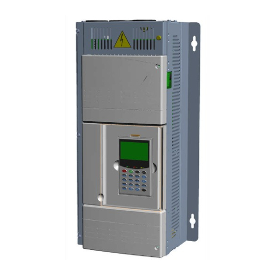
“BPR50” power supply and thyristors driver “GAAPA” power supply for “SYSTEM2” TYPICAL USE Typical use of the SPDM CONTROL BOX is the remote control of a SILCOPAC D thyristor bridge via fiber optics. Eight fiber optics are used to carry the firing pulses and the Forward/Reverse bridge commands. - Page 22 2 – COMPOSITION SPDM CONTROL BOX Figure 2-1 NIDEC ASI S.P.A. – SPDM CONTROL BOX USER MANUAL IMSPDCB2EN...
- Page 23 SPDM CONTROL BOX 2 – COMPOSITION Flat cables connections NIDEC ASI S.P.A. – SPDM CONTROL BOX USER MANUAL IMSPDCB2EN...
-
Page 24: Control Board "System2" (Cod. 1000261943)
The chopping function can be enabled or disabled by means the jumper JP4 on the GPSIA board. Normally, the chopping function on the GPSIA board is disabled. NIDEC ASI S.P.A. – SPDM CONTROL BOX USER MANUAL IMSPDCB2EN... -
Page 25: Gpsia Layout
300V < Va< 570V 380V < Va< 720V 450V < Va< 860V 17 open 15 open 16 open 570V < Va< 900V 720V < Va< 1100V 860V < Va< 1300V 17 closed NIDEC ASI S.P.A. – SPDM CONTROL BOX USER MANUAL IMSPDCB2EN... -
Page 26: Fiber Optics Board "Gifoa" (Cod. 1000253641)
GIFOA there must be mounted also the board GPTRA which performs the chopping function on the pulses sent to the “P” board. In the near figure, the GIFOA board is colored in brown. 2.5.1 GIFOA Layout NIDEC ASI S.P.A. – SPDM CONTROL BOX USER MANUAL IMSPDCB2EN... -
Page 27: Connectors
GPTRA is mounted on both the GIFOA boards: on the transmitting GIFOA (TX) mounted inside the control box and on the receiving GIFOA (RX) mounted inside the SILCOPAC D. In both cases the chopping action of GPTRA should be enabled to transform the solid pulse in a pulse train. NIDEC ASI S.P.A. – SPDM CONTROL BOX USER MANUAL IMSPDCB2EN... -
Page 28: Gptra Layout
Board P customizing Before applying power to the P board, verify the following connections: X6 - X7 closed X60 - X61 closed X62 - X63 closed A - B closed NIDEC ASI S.P.A. – SPDM CONTROL BOX USER MANUAL IMSPDCB2EN... -
Page 29: Ct Load Resistors
As alternative, the burden resistors can be placed outside the control box connecting them to the terminals X10A-7 and X10A-8. The connection to the external burden resistors should be made using a 1m maximum length of unshielded twisted-pair with section of 2.5 mm (AWG14). NIDEC ASI S.P.A. – SPDM CONTROL BOX USER MANUAL IMSPDCB2EN... -
Page 30: P Board Terminals And Test Points
A - C Uni-directional converter connection. +24 V supply voltage test point. +15 V supply voltage test point; adjusted by trimmer P1. P15s +15 V held supply voltage test point. NIDEC ASI S.P.A. – SPDM CONTROL BOX USER MANUAL IMSPDCB2EN... -
Page 31: Power Supply Board "Gaapa" (Cod. 1000080550)
SYSTEM2 plus the SYSENC boards. GAAPA is mounted on the back of the control box. The GAAPA has a protection fuse of 6.3A, 250V. NIDEC ASI S.P.A. – SPDM CONTROL BOX USER MANUAL IMSPDCB2EN... -
Page 32: Switched Mode Power Supply (Cod. 8000002668)
The SYSENC has two terminals for the feeding the encoder at 5V (max 100mA) or 24V (max 150mA). If a higher power level is needed to supply the encoder, provide an external power supply unit that should be mounted as close as possible to the encoder. NIDEC ASI S.P.A. – SPDM CONTROL BOX USER MANUAL IMSPDCB2EN... - Page 33 The failure to ground connect the shield to both ends, due to noise voltage, can cause the breakage of the line driver of the encoder and/or of the drive receiver. NIDEC ASI S.P.A. – SPDM CONTROL BOX USER MANUAL IMSPDCB2EN...
-
Page 34: Connection And Jumpers Presetting With System Board
The table below shows the assignment of the signals of the encoder inputs to removable terminal 9-pin connector on the encoder interface mezzanine. Terminal Signal ENC-A ENC-A/ ENC-B ENC-B/ ENC-Z ENC-Z/ GNDE +5VE (max. 100mA) +24VE (max. 150mA) Table 2-3: Signal assignment of the connector J3 module SYSENC. NIDEC ASI S.P.A. – SPDM CONTROL BOX USER MANUAL IMSPDCB2EN... - Page 35 Encoder Expansion Board P3 1-2 o 2-3 =ON Encoder 0Enc 5VEnc 24VEnc Encoder push-pull, 12/24 supply. System Board P1 OFF Encoder Expansion Board P2 OFF P3 OFF Encoder 0Enc 5VEnc 24VEnc NIDEC ASI S.P.A. – SPDM CONTROL BOX USER MANUAL IMSPDCB2EN...
- Page 36 2 – COMPOSITION SPDM CONTROL BOX This page is intentionally left blank. NIDEC ASI S.P.A. – SPDM CONTROL BOX USER MANUAL IMSPDCB2EN...
-
Page 37: 3 - System2 Board
SPDM CONTROL BOX 3 – SYSTEM2 BOARD “SYSTEM2” BOARD Figure 3-1 shows the layout of the SYSTEM2 control card. Figure 3-1: SYSTEM2 Layout. NIDEC ASI S.P.A. – SPDM CONTROL BOX USER MANUAL IMSPDCB2EN... -
Page 38: Jumpers, Switches And Buttons
This section describes the jumper settings. It is recommended to shut down the power of the card before configuration of the jumpers. The following figure shows the layout of the jumpers on the component side. Figure 3-2: Jumpers layout. NIDEC ASI S.P.A. – SPDM CONTROL BOX USER MANUAL IMSPDCB2EN... - Page 39 2-3 (default) Table 3-2: Configuration of jumper P3. NOTE: In the SPDM CONTROL BOX, P3 must be set on default position 2-3. 3.1.1.3 P4, TERMINATION OF THE SERIAL LINE OF KEYPAD The P4 jumper allows you to insert the termination of the RS485 serial line to logic level for the keypad interface available on the J11 connector.
- Page 40 $FFF0.0100 Table 3-6: Configuration of jumper P16. NOTE: In the SPDM CONTROL BOX, P16 must be set on default position 1-2. 3.1.1.8 P20, SELECTION OF THE SOURCE FOR ADCINA1 The P20 jumper selects the source of the analog input ADCINA1 of DSP. The table below illustrates this configuration.
- Page 41 SPDM CONTROL BOX 3 – SYSTEM2 BOARD NOTE: In the SPDM CONTROL BOX, P20 must be set on default position 1-2. 3.1.1.9 P21, SELECTION OF THE SOURCE FOR ADCINA4 The P21 jumper selects the source of the analog input ADCINA1 of DSP. The table below illustrates this configuration.
-
Page 42: Buttons
In the table below it is shown the configuration of the switches SW2. SW2 position Type of analog input Current (0÷20mA) Voltage (±12V) (Default configuration) Table 3-14: Configuration of SW2. NIDEC ASI S.P.A. – SPDM CONTROL BOX USER MANUAL IMSPDCB2EN... -
Page 43: Connectors
SPDM CONTROL BOX 3 – SYSTEM2 BOARD Connectors 3.2.1 Description of the connectors The following figure shows the layout of the connectors on the board. Figure 3-3: Layout of Connectors. NIDEC ASI S.P.A. – SPDM CONTROL BOX USER MANUAL IMSPDCB2EN... -
Page 44: J16, Connector Modbus
3.2.3 J17, connector CANBus CAN BUS interface is available on a removable 5-pole terminal. The correspondence between the terminal and the CAN bus signal is illustrated in the table below. NIDEC ASI S.P.A. – SPDM CONTROL BOX USER MANUAL IMSPDCB2EN... -
Page 45: J18, Auxiliary Opto-Isolated Digital Outputs
Each of the 7 digital output is an open emitter with maximum source current of 50mA and 24V. Signal Signal ME-D04 ME-D05 ME-D06 ME-D07 ME-D08 ME-D09 ME-D10 Table 3-18: connector J18 signal assignment NIDEC ASI S.P.A. – SPDM CONTROL BOX USER MANUAL IMSPDCB2EN... -
Page 46: J19, Connector Profibus Dp
In the picture below you can see the location and numbering of terminals on SYSTEM2 card. Figure 3-5: Front view of the removable terminal blocks The table below shows the assignment of the removable terminal block signals. NIDEC ASI S.P.A. – SPDM CONTROL BOX USER MANUAL IMSPDCB2EN... - Page 47 Table 3-20: Signal assignment for the removable terminal block. The signal on terminal 35 depends on the jumper P28 configuration. NC = Contact normally closed COM = Common contact NO = Contact normally open NIDEC ASI S.P.A. – SPDM CONTROL BOX USER MANUAL IMSPDCB2EN...
-
Page 48: Leds
3 – SYSTEM2 BOARD SPDM CONTROL BOX LEDs 3.3.1 Description of the onboard LEDs The following figure shows the layout of the LEDs and switches on the board. Figure 3-6: Layout of LEDs. NIDEC ASI S.P.A. – SPDM CONTROL BOX USER MANUAL IMSPDCB2EN... -
Page 49: Dl1 Dl4, Dl6, General Purpose Led
DL12, monitor of signal ABIL_A The DL12 LED monitors the ENABLE signal of the drive A (DSP pulse enable command). It lights on when the ENABLE signal of the drive A is active. NIDEC ASI S.P.A. – SPDM CONTROL BOX USER MANUAL IMSPDCB2EN... -
Page 50: Dl13, Monitor Of Signal Driveok_A
The "SYSENC" module must be installed in its housing on SYSTEM2 tab at the J14 connector and three mounting holes D, E and F. Use 3MA x 8mm screws to secure the mezzanine card SYSTEM2. The following figures are shown side view and top of the installed module. NIDEC ASI S.P.A. – SPDM CONTROL BOX USER MANUAL IMSPDCB2EN... -
Page 51: P1, P2 E P3, Jumpers For The Differential Lines Termination
Line not terminated Line terminated at 220 Line terminated at 110 Table 3-22: Configuration of jumpers P1, P2 and P3 on module SYSENC. 3.4.4 J2, connector for power supply of module SYSENC. NIDEC ASI S.P.A. – SPDM CONTROL BOX USER MANUAL IMSPDCB2EN... -
Page 52: J3, Encoder Inputs Removable Terminal Blocks
DL1, monitor of power supply +24V The LED DL1 monitors the presence of a + 24V voltage on terminal 19 of J3. It lights up when power supply is applied to the mezzanine. NIDEC ASI S.P.A. – SPDM CONTROL BOX USER MANUAL IMSPDCB2EN... -
Page 53: Maintenance
No button. You will go directly to the Downloading the Firmware section. If you are upgrading an existing Drive click on the Yes button. Fig. 4.4-3 - Save drive parameter values ? NIDEC ASI S.P.A. – SPDM CONTROL BOX USER MANUAL IMSPDCB2EN... - Page 54 Leave them as they are. Initially Next and Finish button are disabled. You have to click on the red Download Firmware! button to proceed. Fig. 4.4-7 - Download Firmware. OK to start NIDEC ASI S.P.A. – SPDM CONTROL BOX USER MANUAL IMSPDCB2EN...
- Page 55 It is a quite long process so please be patient. A Cancel Wait button is available if you want to stop waiting for drive reboot (Not Recommended!). Fig. 4.4-12 - Download Firmware. Waiting for the installation process NIDEC ASI S.P.A. – SPDM CONTROL BOX USER MANUAL IMSPDCB2EN...
- Page 56 When the update process starts you will have to wait for it to complete. The Next button will be enabled when restore process is complete. Fig. 4.4-16 - Restoring drive parameter values process started NIDEC ASI S.P.A. – SPDM CONTROL BOX USER MANUAL IMSPDCB2EN...
- Page 57 This is the final step. All the Drive Firmware setup process has been performed. You can click on the Finish button to exit Fig. 4.4-19 - Conclusion of the Firmware Upload Procedure NIDEC ASI S.P.A. – SPDM CONTROL BOX USER MANUAL IMSPDCB2EN...
- Page 58 4 - MAINTENANCE SPDM CONTROL BOX This page is intentionally left blank. NIDEC ASI S.P.A. – SPDM CONTROL BOX USER MANUAL IMSPDCB2EN...
Need help?
Do you have a question about the SPDM CONTROL BOX and is the answer not in the manual?
Questions and answers