Table of Contents
Advertisement
Quick Links
Advertisement
Table of Contents
Troubleshooting

Subscribe to Our Youtube Channel
Related Manuals for Nidec MCE Motion 2000 Touch Screen


Summary of Contents for Nidec MCE Motion 2000 Touch Screen
- Page 1 Motion Control Engineering 11380 White Rock Road Rancho Cordova, CA 95742 voice 916 463 9200 fax 916 463 9201 https://acim.nidec.com/elevators/motion-control-engineering Motion 2000 Touch Screen User Guide V20 software Manual 42-02-1P28, Rev A3 May 2023...
- Page 2 Copyright This document is owned and copyrighted by Motion Control Engineering. All Rights Reserved. Upon request by Motion Control Engineering, this document must be returned to Motion Control Engineering. ©Motion Control Engineering, 2023 Trademarks All trademarks or registered product names appearing in this document are the exclusive property of the respective owners.
- Page 3 End User License Agreement This End User License Agreement (“Agreement”) grants you the right to use the software contained in this product (the “Software”) subject to the following restrictions: You may not: (i) copy the Software, except for archive purposes consistent with your standard archive procedures; (ii) trans- fer the Software to a third party apart from the entire product;...
-
Page 4: Safety Precautions
Important Precautions and Useful Information This preface contains information that will help you understand and safely maintain MCE equipment. We strongly recommend you review this preface and read this manual before installing, adjusting, or maintaining Motion Control Engineering equipment. This preface dis- cusses: •... -
Page 5: Environmental Considerations
Proper grounding is vitally important to safe and successful operation. Bring your ground wire to the system subplate. You must choose the proper conductor size and minimize the resistance to ground by using the shortest possible routing. See National Electrical Code Article 250-95 or the applicable local electrical code. -
Page 6: In This Manual
In This Manual: This manual is the installation, adjustment, and troubleshooting guide for the HMC-2000 car control. When viewed online as a pdf file, hyperlinks (buttons or blue text) link to related topics and informational websites. The manual includes: • Contents: Table of Contents. -
Page 7: Table Of Contents
Contents Safety and Other Symbol Meanings ........1-iv Safety Precautions . - Page 8 Pit Flood Operational State ..........1-20 User Interface .
- Page 9 Settings and Jumpers ............3-4 Temporary Jumpers .
- Page 10 Motor/Valve Limit Timer ........... . 4-8 Relevel Operation .
- Page 11 MC-LSI Landing System Interface Board ........5-41 LSI Connections .
- Page 12 Normal Operation ............6-29 MC-CPI-2 Car Panel Interface Board .
-
Page 13: Section 1. M2000 Ts Description
• General Information • Controller Descriptions • User Interface • Specifications • Landing System • Operating Modes M2000 TS Description General Information Motion 2000 TS supports simplex, duplex, or group control. Motion 2000 TS design achieves simple inter-connectivity and easy field expansion through CAN BUS technology, phone-style connectors and optimized field connection locations. - Page 14 M2000 TS Description The job prints accompanying your Motion 2000 TS controller are the primary document neces- sary to install the controller and additional equipment (if ordered from MCE). The job prints and this manual together provide the information necessary to install, adjust, and troubleshoot the Motion 2000 TS elevator controller.
-
Page 15: Car Controller Description
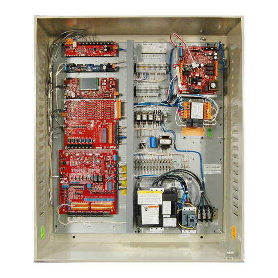
Car Controller Description Car Controller Description Motion 2000 TS controllers comply with the latest A17.1/B44 Elevator Safety Code. A typical Motion 2000 TS controller is shown below. Typical board types are called out on the following page. Manual # 42-02-1P28 A3 1-3... - Page 16 M2000 TS Description Figure 1.1 Typical Board Complement (Layout varies) HC-CHP CAN Hub/ Power Supply ICE-SF-2 Serial Fixture Board HC-MPU-2-TS Main Processor Unit HC-UIO-2 Universal Input / Output Board HC-DVR Driver Board HC-CTL-2 Control Board 1-4 Manual # 42-02-1P28 A3...
-
Page 17: Controller Circuit Boards
Car Controller Description Controller Circuit Boards HC-CHP, CAN Hub and Power Supply: Provides a central connection point for the Controller Area Network (CAN). Also provides 16Vac power for digital integrated circuits throughout the controller. For more information see “HC-CHP CAN Hub and Power Supply Board”... - Page 18 M2000 TS Description HC-UIO-2 Universal Input/Output Board Depending upon the board configura- tion, HC-UIO-2 boards may be used for programmable inputs and outputs (16 per board), car and hall calls, and dispatching. In all cases, the functionality of the HC-UIO-2 board can be expanded by plugging in additional boards.
- Page 19 Car Controller Description Figure 1.4 HC-CTL-2 Main Control Board HC-CTL-2 Main Control Board HC-CTL-2 Main Control Board monitors I/O, performs safety functions and door operation. The HC-CTL-2 board is responsible for inspection, fire service, landing system, door lock bypass and lanterns and gongs. For more information see “HC-CTL-2 Control Board”...
- Page 20 M2000 TS Description ICE-SF-2 Serial Fixture Board Interfaces with serial fixtures. ICE-COP-2 Low Voltage I/O Board Converts programmable I/O (24 per board) to CAN bus to be read/written by the controller 1-8 Manual # 42-02-1P28 A3...
-
Page 21: Mc-Cpi-2 Car Panel Interface Board
Car Controller Description MC-CPI-2 Car Panel Interface Board Converts the Discrete closures from car panel buttons and switches to CAN data and passes it through the Landing System Interface board (MC-LSI) to the car controller or dispatcher. MC-LSI Landing System Interface Board Provides a connection point for the Car Panel Interface board (MC-CPI-2). -
Page 22: Specifications
M2000 TS Description Specifications This section lists specification and feature set information for hydraulic installations. • Environmental and Power Input • Standardization and Code Compliance • Operating Modes • Operating Mode Definitions Table 1.1 Environmental and Power Input Topic Description Enclosures NEMA 1 standard, others available Temperature... - Page 23 Specifications Table 1.3 Operating Modes Topic Description Inspection Operation Cartop inspection Car panel inspection Hoistway access inspection Machine room inspection Construction Fault Bypass Faults bypassed operation using run box or inspection controls. See Faults Bypass note. Inspection Fault Bypass Faults bypassed operation using inspection controls. See Faults Bypass note.
-
Page 24: Operating Mode Descriptions
M2000 TS Description Operating Mode Descriptions Controller Operating Modes are mutually exclusive, meaning the elevator controller may only be in one mode at any time. Available operating modes are configured when the car is installed. Not all modes are available on all cars. This section describes controller operating modes. Modes are listed by priority below:, including: •... -
Page 25: Inspection Operation
Specifications Inspection Operation In inspection, a car operates at the set inspection speed using up and down buttons or momen- tary switches. The car will stop as soon as the buttons are released. Inspection operation may be controlled from three locations. For safety purposes, locations have a priority: •... -
Page 26: Hoistway Access Inspection
M2000 TS Description Mode Entry • Bring the car to the desired floor. • Place the car on in-car inspection. • Use UP or DOWN buttons to run the car. Hoistway Access Inspection At both top and bottom access hall stations, a three-position, key operated switch allows the car to be moved to gain top or bottom access. -
Page 27: Construction Operation
Specifications Construction Operation Construction operation is for use when all hoistway equipment may not yet be installed. On Construction operation, the car is moved using cartop or machine room inspection inputs. Mode Entry • The INSP/NORM switch on the HC-CTL-2 board must be in INSP position. •... -
Page 28: Emergency Medical Service Mode
M2000 TS Description Fire Recall Mode Fire recall operation (Fire Phase I) recalls the elevator to a designated fire recall floor (main or alternate) and removes it from passenger operation. Fire recall can be initiated by smoke detec- tors or by a fire recall switch. At the recall floor, the car will wait with doors closed or open (as configured). -
Page 29: Cfss Phase Ii (In-Car) Mode
Specifications CFSS Phase II (In-Car) Mode CFSS Phase II should initiate after the elevator has arrived at the recall floor. The hospital staff, or VIP can then take control of the car and go non-stop to their desired floor. The car can go into CFSS Phase II automatically or be configured to wait for a momentary or constant pressure key switch (CFSS II SW input). -
Page 30: Attendant Mode
M2000 TS Description Attendant Mode Attendant operation allows an operator riding in the car to run the car, choosing run direction, and which hall calls to answer. In this mode: • Doors open automatically when the car is stopped in a door zone. •... -
Page 31: Capture For Test (Pretest) Mode
Specifications • Finish Car Calls • Car Call Lights • Door Buttons • Arrival Lanterns • PI Outputs • Override Security • Initiate: Sabbath Operation is initiated when the spare input SAB is activated. • Operation: In accordance with the description above and servicing stops set through the Sabbath Operation parameter in the Additional Features menu (page 5-18). -
Page 32: Earthquake Operational State
M2000 TS Description Earthquake Operational State Earthquake operation affects all automatic modes of operation. When a seismic input becomes active, the car will stop at the next available floor and shut down. Emergency Power Operational State Emergency Power Operation, if provided, is activated when normal power loss is detected. Emergency power may be provided by a building generator or by a battery powered lowering device. -
Page 33: User Interface
User Interface User Interface System status display, configuration, and diagnostics are through the on-board, color, touch- screen (OBD, On Board Display). No external programming tools are required. You must be on Inspection mode to change and save parameters. The interface provides: •... -
Page 34: Faults And Safety
M2000 TS Description different modes. In our example illustration, the car is on MR (machine room) INSPECTION operation. Please see Operating Modes on page 1-12. The second line of the display shows any events or faults that may be active in yellow text. Usu- ally, this line will be blank. - Page 35 User Interface • DISPATCHER/DISP ID: nn / M-GROUP / SIMPLEX • The designated dispatcher car will show DISPATCHER for this LED. • The designated non-dispatcher car will show DISP: 01 or DISP: 02, telling the viewer which car ID is the dispatcher (when cars are communicating). •...
-
Page 36: Menu Overview
M2000 TS Description Menu Overview Table 1.5 Config 01, 02, and 03 Topic Description Config 01 Building Setup Controller type, floor information, Fire code and recall floors, landing system type. Job Info and Labels Job information, car and floor labels Elevator Features Capture and recall floors, car behavior, anti-nuisance Configure Spare Inputs... - Page 37 User Interface Table 1.8 System Diagnostics Topic Description Event Log Time-based logging of system events Door Control View door control signal status Diagnostics Tree Safety related signal activity flags Landing System View landing system signal status Active Events View currently active system events Table 1.9 Car Diagnostics Topic Description...
- Page 38 M2000 TS Description Table 1.14 Status Information Topic Description CPU-Bus-Com Status Conditions affecting microprocessor communication with activity indicator Monitoring Tools Reset Xport, Default Password, TFTP Status Can Bus Viewer View CAN bus device IDs and related messaging activity. Version Information Software version information Other Car Settings Second car settings display for duplex operation, Sabbath Mode, etc.
-
Page 39: Landing System
Landing System Landing System The landing system is designed to be mounted on the car top. Landing systems used with the Motion 2000 TS controller includes the LS-EDGE. LS-EDGE Landing System The LS-EDGE positioning system uses hall-effect sensors and perforated steel tape to report position as the car moves through the hoistway. - Page 40 M2000 TS Description Figure 1.6 LS-EDGE Components Top hanger assembly (diagonal brace not shown) LS-TAPEMNTOP-EDGE Together, these are assembly LS-TAPEMNT-EDGE Bottom hanger assembly LS-TAPE MNTBOT-EDGE Sensor assembly LS-EDGE Steel tape, magnets & connecting cables not shown 1-28 Manual # 42-02-1P28 A3...
-
Page 41: Section 2. Installation
• In this Section • Safety Precautions • Installment Considerations • Machine Room Preparation • Piping and Wiring • Recommended Tools • Wiring Prints • Controller Installation • General Wiring Guidelines Installation In this Section This section contains important recommendations and instructions for installing the Motion 2000 TS Hydraulic controller. -
Page 42: Safety Precautions
Installation Safety Precautions Certain fundamental warnings must be kept in mind at all times to help avoid severe personal injury or equipment damage. Personal Safety • Motion 2000 TS Controllers should only be installed by qualified, licensed, trained eleva- tor personnel familiar with the operation of microprocessor-based elevator controls. •... -
Page 43: Installation Considerations
Installation Considerations Installation Considerations 1. Dust, carbon, or metallic particles should not be allowed to accumulate on any part of the control. 2. Avoid vibration and shock. 3. Avoid rapid temperature change, high humidities, high ambient temperatures. 4. Avoid caustic fumes. 5. -
Page 44: Piping And Wiring
Installation Piping and Wiring Proper routing of signal and power wires for the car and dispatcher is essential to trouble free installation of microprocessor based equipment. Low voltage and high voltage wiring cannot be run in the same conduit, duct, or tray. How Electrical Noise Occurs Electrical noise occurs in most cases when two wires run along side one another with one of them a high power conductor and the other a low signal level conductor. -
Page 45: Recommended Tools And Test Equipment
Installation Considerations Recommended Tools and Test Equipment For proper installation, use the following tools and test equipment: • A digital multimeter, Fluke series 75, 76, 77 or equivalent • A clamp-on AC ammeter • Hand-held radios or cell phone • Test weights •... -
Page 46: Nomenclature
Installation Nomenclature A listing of PC boards and their designator numbers plus other schematic symbols used in the wiring prints can be found at the beginning of the Job Prints and in the Component Nomencla- ture table below. • Become familiar with the Elevator Car Wiring Print drawing number -1. •... -
Page 47: Controller Installation
Controller Installation Controller Installation Mount the controller securely to the machine room wall or other appropriate location and knock out holes to install a raceway or conduit to permit the routing of wires into the cabinet. Note that the standard MCE control cabinet does not require rear access. Caution Do not allow any metal chips or drill shavings to fall into the electronics. -
Page 48: General Wiring Guidelines
Installation General Wiring Guidelines Basic wiring practices and grounding requirements are discussed in this section. Proper Grounding Procedures MCE cannot provide specific advice regarding equipment grounding (or bonding), as each building is unique in its construction, and local codes may differ significantly from national codes. -
Page 49: Main Ac Power
General Wiring Guidelines Figure 2.1 Ground Wiring to Controller Cabinets • Direct solid grounding must be provided in the machine room to properly ground the con- troller and the motor. Indirect grounding, such as the building structure or a water pipe, may not provide proper grounding and could act as an antenna radiating RFI noise, thus, disturbing sensitive equipment in the building. - Page 50 Installation 2-10 Manual # 42-02-1P28 A3...
-
Page 51: In This Section
• In this Section • Check for Shorts to Ground • Before Applying Power • Applying Power • Construction Operation • Verifying Starter Operation • Hoistway Installation • LS-Edge Installation • Hoistway Learn Operation • Door Position Monitor • Complete Field Wiring •... -
Page 52: Check For Shorts To Ground
Startup - Inspection Operation Check for Shorts to Ground Check for shorts to ground before powering up the system. Set the meter for resistance mea- surement (100 to 200 ohm range). Take all measurements with respect to the 1-bus, which is also referred to as the system common or common elsewhere in this manual. -
Page 53: Applying Power
Applying Power Applying Power Initial Adjustments and Power Phasing When performing the following steps please exercise extreme caution to prevent personal injury or damage to components and equipment. Have someone stand by the main power dis- connect switch during the following phases of the start up procedure for added safety: •... -
Page 54: Set Up For Construction Operation
Startup - Inspection Operation Set Up for Construction Operation If required, it is possible to run the car during construction to help complete work in the hoist- way. If they are in place, cartop controls may be used or the car may be run from the controller or a temporary run box. -
Page 55: Temporary Jumpers
Set Up for Construction Operation Minimal equipment requirements are: • Pump motor and valves. • SAFH, SAFC: Hoistway and car safety devices. Connecting 2 bus to these terminals (as described in Table 3.1) will cause relay SAFS on the HC-CTL-2 board to pick and light the SAFS indicator (provided no safety-dropping faults are present). -
Page 56: Temporary Run Box Hookup
Startup - Inspection Operation Temporary Run Box Hookup The following illustration shows a temporary run box hookup. Disconnect controller power before attempting to wire the run box. The temporary run box must have an enable button, an up button, a down button, an inspection switch, and a stop switch. Caution For safety, keep the controller Machine Room Inspection switch in the INSP position while the Temporary Run Box is in use. -
Page 57: Verifying Proper Starter Operation
Verifying Proper Starter Operation Verifying Proper Starter Operation 1. Verify that any fuses removed during the ground check have been reinstalled. If not, turn power OFF at the Main Power Disconnect switch, reinstall the fuses and then turn power back ON. Verify that the Machine Room Inspection Mode switch on HC-CTL-2 board is in the INSP position. - Page 58 Startup - Inspection Operation Y-DELTA Starter The Y contactor picks first. Then after a programmable delay, depen- dent upon the UP TO SPEED DELAY (CONFIG 02>SYSTEM CONTROL PARAMETERS>UP TO SPEED) timer, the Y contactor should drop then after another programmable delay, depen- dent on the STARTER W-D TRANSITION (CONFIG 02 >SYSTEM CONTROL PARAMETERS>...
-
Page 59: Hoistway Control Equipment Installation
Hoistway Control Equipment Installation Hoistway Control Equipment Installation This section covers the recommended procedures for installing the LS-EDGE landing systems. LS-EDGE Installation The LS-EDGE positioning system uses hall-effect sensors and perforated steel tape to report position as the car moves through the hoistway. 5.5-inch magnets are used at each door zone; one row for front openings, a second for rear openings. -
Page 60: Ls-Edge Tape Installation
Startup - Inspection Operation LS-EDGE Tape Installation Before installing perforated tape, ensure adequate clearance from beams, walls, counterweight, cab, and terminal limit devices. Make sure the sensor is not placed so close to the governor lift arm that, when the car safeties are activated, the sensor is damaged or the car safeties cannot apply. -
Page 61: Ls-Edge Bottom Hanger Assembly
Hoistway Control Equipment Installation 3. Adjust extended strut length as required (tape suspended as close to the guide rail as adequate clearances will allow to reduce loading on end of Unistrut channel). Secure rail mounting hardware (40 - 50 ft lbs.). (The tape hanger slides in the strut for fine adjust- ment later.) 4. -
Page 62: Ls-Edge Broken Tape Switch
Startup - Inspection Operation LS-EDGE Broken Tape Switch The normally closed contacts on the Broken Tape Switch are used to detect a broken tape condi- tion. The switch is mounted backwards for protection during shipment. Remove it and mount it shown. - Page 63 Hoistway Control Equipment Installation Figure 3.6 Sensor Mounting LED Indicators UP 40 - 50 ft lbs “L” bracket (provided) Customer provided unistrut CAR TOP Sensor Alignment After the tape has been installed, check the sensor alignment. The sensor should not ride hard on either side of the Unistrut bracket during any part of travel through the hoistway.
-
Page 64: Ls-Edge Door Zone Magnets
Startup - Inspection Operation LS-EDGE Door Zone Magnets 5.5-inch strip magnets are used at each floor/opening position. Front and rear magnet align- ment is shown on the sensor top label. Looking at the perforated tape from the elevator car, the magnets for the front door zone are mounted to the left of the perforated holes;... -
Page 65: Ls-Edge Terminal Magnets
Hoistway Control Equipment Installation LS-EDGE Terminal Magnets Special striped magnets are used to designate the top and bottom terminals. The length of the terminal magnets depends upon car speed, the aggressiveness of the slowdown, and the travel distance between level at floor and end of travel. Figure 3.8 Motion 2000 TS Bottom Terminal Magnets 40-11-0028 40-11-0027... - Page 66 Startup - Inspection Operation Figure 3.9 Motion 2000 TS Top Terminal Magnets 40-11-0028 40-11-0027 40-11-0028 Table 4. Suggested Length of Terminal Magnet Before Leading Edge of DZ Magnet Length of Terminal Magnet Length of Terminal Magnet Car Speed Car Speed Preceding Floor Zone Magnet Preceding Floor Zone Magnet 110 fpm...
-
Page 67: Ls-Edge Terminal Magnet Logic
Hoistway Control Equipment Installation LS-EDGE Terminal Magnet Logic The terminal limits from the LS-EDGE are positional back-up only. The controller uses serial counter data to adjust speed depending on the positions of the virtual limits. The LS-EDGE magnet logic provides a redundant means of terminal limits. •... -
Page 68: Hoistway Learn Operation
Startup - Inspection Operation Hoistway Learn Operation Hoistway Learn (Landing System Learn) After installing the leveling and terminal magnets and setting step up/step down distances, you will need to perform a learn operation to learn floor and switch positions. If floor level magnets have not been positioned accurately enough, any offset can be adjusted in software (+/- 1 inch). -
Page 69: Door Position Monitor Switch (If Used)
Hoistway Learn Operation Initial Stepping Positions The initial settings for the run up and run down stepping positions were set at the factory using the following table (Gray area applicable to Motion 2000 TS). When running up to a floor, the floors step up position forces the elevator to drop high speed. -
Page 70: Ls-Edge Short Floors
Startup - Inspection Operation LS-EDGE Short Floors A landing that is too close to an adjacent landing such that, on a one-floor run, the car fails to reach contract speed before reaching the stepping (Step Up/Dn) distance for the destination floor is termed a Short Floor (see figure below). -
Page 71: Complete The Installation And Field Wiring
Complete the Installation and Field Wiring Complete the Installation and Field Wiring Refer to the job prints and complete the installation of equipment and field wiring to the con- troller, including: • Car Operating Panel (COP) switches and indicators • Fire Service detectors and indicators •... - Page 72 Startup - Inspection Operation 3-22 Manual # 42-02-1P28 A3...
-
Page 73: In This Section
• In this Section • Onboard Diagnostics • Troubleshooting Reference • Test Mode Operation • Running on Test/Normal • Final Adjustments on Test • Final Adjustments on IND • Final Adjustments on Normal • Final Testing on LS-Edge • Passcode (Restricted Mode) •... -
Page 74: Diagnostic Messages And Input/Output Signals
Final Adjustment Diagnostic Messages and Input/Output Signals To speed up final adjustment and troubleshooting, become familiar with the Status and Error Messages and Input/Output signals. Note It will also be helpful to become familiar with the Motion 2000 TS Controller’s computer. See The HC-MPU-2-TS Main Processor Unit on page 5-2 Screen Descriptions on page 5-7. -
Page 75: Troubleshooting Reference
Troubleshooting Reference Troubleshooting Reference Danger Always observe safety precautions when troubleshooting. Lethal voltages are present. This section includes: • Bus voltage testpoints and fuse locations • Touch screen tools • Circuit board descriptions • Fault Message Descriptions System I/O At this level, inputs and outputs are grouped separately and alphabetically with no deference to their function. -
Page 76: Car, Motion, Group, Pld Diagnostics
Final Adjustment CAR, MOTION, GROUP, PLD Diagnostics These screens provide useful in depth diagnostics for the car and system control operations (Car Operation, Car Motion Control Controller System, Group Control, and PLD). Flags are vis- ible indicators of active signals, descriptively labeled so you can understand what they repre- sent. -
Page 77: Stats
Troubleshooting Reference Stats Collected statistics for maintenance and system activity. • Maintenance Statistics: Collected run-related statistics. Compiled until manually cleared. • Hourly Statistics: Car and hall call statistics per hour for the preceding 24 hours. • Hall BUS Inventory: Monitor/check each node board's I/O and load status. When all hall calls are installed and functioning properly use the INVTRY control on this screen to add them to system memory. -
Page 78: Test Mode Operation
Final Adjustment Test Mode Operation The purpose of TEST mode is to allow easy and convenient full-speed operation of the car so that the final adjustments can be made without cycling the doors. When the elevator is operated in the TEST mode, the elevator doors do not open. The door open functions are disabled during TEST mode operation. -
Page 79: Running On Test/Normal Mode
Running on Test/Normal Mode Running on Test/Normal Mode Caution If the door operator is not working, pull the door fuses and close the doors so that the door clutch will not hit any of the door lock rollers. Take whatever steps are necessary to keep the installation safe, but make sure that the car top is still accessible after closing all of the doors. -
Page 80: Final Adjustments On Test Mode
Final Adjustment Final Adjustments on Test Mode The following final adjustments should be made with the elevator operating on Test mode (Con- troller Test Switch on the HC-CTL-2 board in the TEST position). The LCD display should indi- cate TEST MODE. Hydraulic Valves Adjust hydraulic valves for proper speed, acceleration, deceleration, etc. -
Page 81: Final Adjustments On Independent Service
Final Adjustments on Independent Service Final Adjustments on Independent Service The following final adjustments should be performed with the elevator operating on Indepen- dent Service. • Place the CONTROLLER TEST SW on the HC-CTL-2 board in the NORM position. • Place the Independent Service switch in the IND position. •... -
Page 82: Final Adjustments On Normal Operation
Final Adjustment Final Adjustments on Normal Operation The following final adjustments should be performed with the elevator operating on Normal operation. • Place the CONTROLLER TEST SW on the HC-CTL-2 board in the NORM position. • MACHINE ROOM INSPECTION MODE switch on the HC-CTL-2 board in the NORM position. -
Page 83: Remote Governor Testing (Roped Hydro)
Final Adjustments on Normal Operation Remote Governor Testing (Roped Hydro) For a roped hydro installation, the following procedure describes the remote testing procedure for a Wittur Model OL35-NA governor. Static Testing Refer to the Operating Instructions supplied with the governor. Section 4 of these instructions should be closely adhered to. -
Page 84: Final Testing, Ls-Edge Only
Final Adjustment Final Testing, LS-EDGE Only Bottom Terminal Slowdown Limit Tests To test the Normal Stopping Means 1. Remove the wires from terminals LIM0 and LIM1 on the HC-CTL2 board. 2. Apply 24VDC to the LIM0 and LIM1 terminals. 3. Under CONFIG 2 > HOISTWAY SETUP, note the Floor Step Down XX distance (XX represents the bottom landing). -
Page 85: Stop Ring Test
Final Testing, LS-EDGE Only To test the Normal Terminal Stopping Device 1. Remove the wires from terminals LIM2 and LIM3 on the HC-CTL2 board. 2. Apply 24VDC to the LIM2 and LIM3 terminals. 3. Under CONFIG 2 > HOISTWAY SETUP, note the Floor Step Up YY distance. Set it to 0 (zero) to disable it. -
Page 86: Low Oil Condition Testing
Final Adjustment 20. Restore power to the controller at the main disconnect. 21. Take the controller off of Machine Room Inspection (MACHINE ROOM INSPECTION INSP/NORM switch in the NORM position). Low Oil Condition Testing These procedures simulate a low oil condition for testing purposes. Low Oil Switch in use If there is a low oil switch being used, perform the following: 1. -
Page 87: Passcode (Restricted Mode)
Passcode (Restricted Mode) Passcode (Restricted Mode) (If applicable.) Until a valid pass code is entered and saved, the controller will not answer hall calls. If a valid pass code has not been obtained and entered for the job: 1. Contact MCE Customer Service to obtain a pass code. 2. -
Page 88: Release To Normal Operation
Final Adjustment Release to Normal Operation Final testing must be successfully completed before the car may be released for passenger oper- ation. Danger Before the Elevator can be turned over to normal use, it is very important to verify that no safety circuit is bypassed. -
Page 89: Section 5. The Computer
• In this Section • Main Processor • Using the Touchscreen • Touchscreen Organization • Troubleshooting Reference • Touchscreen Events • Event Log • Duplexing The Computer In this Section The Computer is the primary programming and adjustment tool for the Motion 2000 TS sys- tem. -
Page 90: The Hc-Mpu-2-Ts Main Processor Unit
The Computer The HC-MPU-2-TS Main Processor Unit The computer on the Motion 2000 TS Hydraulic Elevator Controller has been designed for easy communication between the mechanic and the controller and between the controller and other computers or data terminals. The computer is used for diagnostic troubleshooting and for pro- gramming the controller. -
Page 91: Buttons And Adjustment Connectors
The HC-MPU-2-TS Main Processor Unit Table 5.1 Status Indicators Indicator Description LED1 Reserved LED2 Reserved FAULT Fault - A fault condition exists. CPU ON Computer On - The MC-MPU processors are functioning properly Motor/Valve Limit Timer - The motor/valve limit timer has elapsed Timed Out of Service - The elevator has been timed out of service FIRE Fire Service - The elevator is on fire service operation... -
Page 92: Using The Touch Screen
The Computer Using the Touch Screen Motion 2000 TS controls use a touchscreen user interface (OBD). The initial (and default) dis- play is the Home Display. Screens are arranged in order of use with the Home screen first, followed by configuration screens, utility screens, and then diagnostics oriented screens. Home Figure 5.2 Home Display Screen (OBD) Menu Tabs... - Page 93 Using the Touch Screen Figure 5.3 Parameter Selection Screen Press and slide to move through multi- ple screens. Tap the arrows to move one screen at a time. Press and hold to move continu- ously. Figure 5.4 Input/Output Assignment Tap on the input or output to be configured. Tap on the input/output name and use scroll arrows or slider to move through potential input/ output assignments.
-
Page 94: Shortcuts
The Computer Figure 5.5 Menu Tree HOME CONFIG 01 CONFIG 02 CONFIG 03 Building Setup Hoistway Setup Building Security Job Info and Labels Door Operation Emergency Power Elevator Features NTS Switches Recall Switches Configure Spare Inputs ETS Switches Network Settings System Timers S-Curve CFSS... -
Page 95: Screen Descriptions
Screen Descriptions Screen Descriptions Experiment with the touch screen to familiarize yourself with navigation and content. If an abbreviation is not clear, please see Acronym Descriptions and Memory Locations on page 5- Table 5.2 Touchscreen Organization and Content Subtab Description Displays critical status information for operation see Home on - Operating Mode... - Page 96 The Computer Table 5.2 Touchscreen Organization and Content Subtab Description Building - Controller Type, Hydraulic Setup - Supervisor Source (Other car, This car, M-Group) - Number of Cars (1 Simplex, 2 Duplex) - Car ID - Call Config Type: Up/Down Collect, Single Collect (Simplex Only), Single Button CONFIG 01 (Simplex Only) NOTE: Duplex can only be Up/Down Collect...
- Page 97 Screen Descriptions Table 5.2 Touchscreen Organization and Content Subtab Description Elevator *- DEDICATED UIO CALL ENABLE: (NONE, CAR, HALL, CAR, HALL) Used when Features the security hall call enable inputs are dedicated on the UIO board. - Calls on UIO-2 Board (None, car, hall, or car and hall) CONFIG 01 - DEDICATED PI ON UIO: (None, stacked, dedicated) - DEDICATED PI TYPE: (0 OFFSET BINARY, 1 OFFSET BINARY, 0 OFFSET GRAY-...
- Page 98 The Computer Table 5.2 Touchscreen Organization and Content Subtab Description Elevator - PHE Cancels CCT (Yes/No) If Yes, photo eye activation cancels the active car call Features dwell timer CONFIG 01 - PHE Cancels HCT (Yes/No) If Yes, photo eye activation cancels the active hall call dwell timer - PHE Cancels LOT (Yes/No) If Yes, photo eye activation will cancel the lobby door dwell timer...
- Page 99 Screen Descriptions Table 5.2 Touchscreen Organization and Content Subtab Description Elevator - ATS Open Side (None, front, rear, both): Which doors to open when Attendant Features Service switch is initially turned on - ATS Stop Cancels CC (Yes/No): If Yes, cancels remaining car call at first car call stop.
- Page 100 The Computer Table 5.2 Touchscreen Organization and Content Subtab Description System - Motor/Valve Time Limit (Default 3 minutes) Starts when the controller Timers attempts to move the car in the up direction and resets when the car reaches its destination floor. If the timer expires before the car reaches its destination, the controller stops trying to move the car up to protect the motor.
- Page 101 Screen Descriptions Table 5.2 Touchscreen Organization and Content Subtab Description Hoistway - LS-EDGE Landing system only. Floor heights are set during hoistway learn Setup operation but may be adjusted here to compensate for floor level magnet position imperfections - Floor Height (n): Level at floor height in inches for each landing - Floor Offset (n): Moves the floor up or down (negative entries) to adjust the CONFIG 02 elevator level position.
- Page 102 The Computer Table 5.2 Touchscreen Organization and Content Subtab Description Door - Manual Doors: (None, Front, Rear, Both) Set for fully manual freight doors Operation - Mechanically Coupled: (None, Front, Rear, Both) Set for the mechanically cou- pled doors - Vertically Sliding (None, Front, Rear, Both) Set for the vertically sliding doors. - DOOR POSITION MONITOR: (Front, Rear, Both, None) Used to specify the CONFIG 02 side where the door position monitor switch is installed.
- Page 103 Screen Descriptions Table 5.2 Touchscreen Organization and Content Subtab Description - U/DSL (1,3,4) Option: Virtual, Physical, or Disabled Switches - USL (1,3,4) Distance: Programmed distance at which the virtual USL2 switch is positioned from terminal floor level. Distance should be set to the same value as Floor Step Up (top floor) distance.
- Page 104 The Computer Table 5.2 Touchscreen Organization and Content Subtab Description Building - Security Enabled: (Yes/No) If Yes, enables car call security. Valid credential Security must be recognized by security system and Car Call Enable signal issued to con- troller before call may be registered - DEDICATED UIO CALL ENABLE: (NONE, CAR, HALL, CAR, HALL) Used when the security hall call enable inputs are dedicated on the UIO board.
- Page 105 Screen Descriptions Table 5.2 Touchscreen Organization and Content Subtab Description Recall Motion 2000 TS provides four car recall inputs, Recall S1 - S4. For momen- Switches tary input activation, set latch timer - Latch Switch(1-4): (Seconds) At recall floor, car will wait for this period of time for an initiating action to be taken (i.e., independent control initiated, access operation initiated, etc.) before automatically returning to normal passenger ser- CONFIG 03...
- Page 106 The Computer Table 5.2 Touchscreen Organization and Content Subtab Description Additional - Sabbath: Enable (Yes/No) Configures the controller to allow Sabbath Operation. Features Sabbath is triggered by spare input SABBATH IN. By default, the car will travel to the highest unsecured Sabbath Floor and then work its way down stopping at every unsecured Sabbath Floor.
- Page 107 Screen Descriptions Table 5.2 Touchscreen Organization and Content Subtab Description File Allows parameters to be backed up and restored: Transfer - Backup Current Settings (to SD) - Restore Backup Settings (from SD) - Restore Factory Settings (from SD) When option is selected, you are prompted to press OK to continue or EXIT to UTILS abort without changing defaults Register...
- Page 108 The Computer Table 5.2 Touchscreen Organization and Content Subtab Description Event Log First In, First Out record of the last 100 events, time and date stamped. Colors: Blue = informational; Yellow = fault; Red = Error; Gray = No longer active Door On/Off status of door control inputs/outputs.
- Page 109 Screen Descriptions Table 5.2 Touchscreen Organization and Content Subtab Description PLD Flags Indicators for PLD related I/O Data register info for PLD Numeric PLD Inputs Indicators for PLD related inputs DIAG Indicators for PLD related outputs Outputs Car Call Conditions affecting car call cancellation and their status Canceled Due To ACTION...
- Page 110 The Computer Table 5.2 Touchscreen Organization and Content Subtab Description CPU Bus Conditions affecting processor communication and their status Com Status Monitoring -Reset XPORT: Resets LAN port on SCHP board STATUS Tools -Default Password INFO -TFTP Status CAN Bus Allows viewing CAN bus data for HC-MPU-2-TS board. Each string provides the ID Viewer of the device and eight packets of Hex data bytes.
- Page 111 Screen Descriptions Table 5.2 Touchscreen Organization and Content Subtab Description View Scope Near real time scope with four trace capacity Landing Select trace signals from landing system System Signals SCOPE System Select trace signals from among dedicated inputs Inputs Pro- Select trace signals from among programmable inputs grammed Inputs...
- Page 112 The Computer Note CAR Diagnostics / Motion Numeric The Motion Flags that reference floor numbers are directly readable and require no code refer- ence (as do the flags intended for use with MCE technical support). Numbers are zero-based; zero = one, 1 = 2, etc. •...
-
Page 113: Spare Input And Spare Output Tables
Spare Input and Spare Output Tables Spare Input and Spare Output Tables Table 5.3 Spare Inputs Input Description NOT USED Input is not used ALIVE Input used in Duplex operation to inform the car that the other car is powered APS ON Auxiliary power supply is on (HAPS) ATS ON... - Page 114 The Computer Table 5.3 Spare Inputs Input Description EMDISP Emergency Dispatch. Sometimes referred to as Wild Operation, takes over in the event of dispatch failure. This input forces this operation EMDISP OV Emergency Dispatch Override. Input that bypasses Wild Operation; when active, car will stay at last call entered, in the event of a dispatcher failure EMSC SW In-car Emergency Medical Service input that transfers car to Phase 2 of emergency medical...
- Page 115 Spare Input and Spare Output Tables Table 5.3 Spare Inputs Input Description HC ENABL Rear Hall Call Enable inputs from the security system for Floors 1 to 8. Used to enable reg- (1R - 8R) istration of secured front hall calls for Floors 1 to 8. Use dedicated UIO board(s) for building with more than 8 floors.
- Page 116 The Computer Table 5.3 Spare Inputs Input Description Redundancy 2L bus. Used to monitor the normally closed contact of an additional 2L relay. RECALL S1 When active, recalls car to programmed floor. See CONFIG 03 Recall Switches RECALL S2 When active, recalls car to programmed floor. See CONFIG 03 Recall Switches RECALL S3 When active, recalls car to programmed floor.
- Page 117 Spare Input and Spare Output Tables Table 5.4 Spare Outputs Output Description BACKUP PWR Battery lowering has been activated by the APS ON input (HAPS/TAPS) CAR DELAY Car has not been able to move. Typically due to doors being held open CAR GONG/R Car gongs CAR LANTDN/R...
- Page 118 The Computer Table 5.4 Spare Outputs Output Description DISAUTOCLSR Disable Auto Close Rear. Used on freight doors that are not controlled by MCE, this output comes when front door auto closing is not allowed (Fire recall complete, Fire Phase II, IND, ATS, Door Hold...).
- Page 119 Spare Input and Spare Output Tables Table 5.4 Spare Outputs Output Description EPOVL BYP R Emergency Power Overlay Bypass Recall output. Activated by the car when the is in ser- vice. Used during the automatic selection during the emergency power phase 2). EPOVL ISV Emergency Power Overlay In Service output.
- Page 120 The Computer Table 5.4 Spare Outputs Output Description OPENING F/R The doors are opening or attempting to open. See output DOF/DOFR OVERLOAD Car is in Overload Status OVERLOAD2 Car is in Overload 2 Status PI OUTPUT (1-8) Position Indicators outputs. Fully configurable for standard binary, gray code or one line per floor.
- Page 121 Spare Input and Spare Output Tables Table 5.5 Acronym Descriptions and Memory Locations Acronym Description and Memory Location From OFF position of switch used to bypass car doors. Used for monitoring switch. Car Door CDBO Bypass Off @ MOTION DIAG > MOTION Inputs Car Door Bypass OFF input from switch on From OFF position of switch used to bypass car doors.
- Page 122 The Computer Table 5.5 Acronym Descriptions and Memory Locations Acronym Description and Memory Location DRDY is a signal from the drive that it is ready to operate. Drive Ready (input to controller) DRDY @ System IO > System Inputs The drive tells the controller that it has control of the motor so it is safe to move the car. Drive Enable (output from controller) @ System IO >...
- Page 123 Spare Input and Spare Output Tables Table 5.5 Acronym Descriptions and Memory Locations Acronym Description and Memory Location Hall Call Hall Call Front Hall Call Time. Defined time for doors to remain open @ CAR DIAG > Door Dwell Timers From ON position of switch used to bypass hoistway doors.
- Page 124 The Computer Table 5.5 Acronym Descriptions and Memory Locations Acronym Description and Memory Location SAFC.P Safety String Car @ MOTION DIAG > MOTION Inputs SAFH.B Safety String Hoistway @ MOTION DIAG > MOTION Inputs SAFP Safety PLD @ PLD DIAG > PLD Outputs SANE(x) Processing device verification @ PLD DIAG >...
-
Page 125: Troubleshooting Reference
Troubleshooting Reference Troubleshooting Reference Danger Always observe safety precautions when troubleshooting. Lethal voltages are present. This section includes: • Bus Voltage Testpoints and Fuse Locations • Touch Screen Tools, page 5-38 • Circuit Board Descriptions, page 5-40 • Fault Message Descriptions, page 5-48 Bus Voltage Testpoints and Fuse Locations Required operating voltages are distributed through fused buses. -
Page 126: Touch Screen Tools
The Computer Table 5.7 Backplane Fuses Description Type FCE1 & FCE2 Voltage for CE Driver Board MDQ/313 FT(X) Voltage for Transformer See labeling in controller. F24V Voltage for Serial Calls AGC/312 Voltage for Card Readers AGC/312 F2CE Voltage to FCE Transformer MDQ/313 Voltage to Valves MDQ/313... -
Page 127: Car, Motion, Group, Pld Diagnostics
Troubleshooting Reference CAR, MOTION, GROUP, PLD Diagnostics These screens provide useful in-depth diagnostics for the car and system controls operations (Car Operation Control, Car Motion Control, Group Controller, System Control, and PLD).For each system processor and for the PLD, these screens can provide information useful for in- depth diagnostics. -
Page 128: Stats
The Computer Stats Collected statistics for maintenance and system activity. • Hall Bus Inventory: When all hall calls are installed and functioning properly use the INVTRY control on this screen to add them to system memory. When troubleshooting hall calls at a future date, use the TEST control to automatically poll and test all switches and lamps. -
Page 129: Mc-Lsi Landing System Interface Board
Troubleshooting Reference MC-LSI Landing System Interface Board The MC-LSI provides a connection point for the landing system and for the Car Panel Interface board (MC-CPI-2) if one is used. The board receives 24 VDC power from an external power sup- ply operating off the controller 2 Bus (120 VAC). - Page 130 The Computer LS-LSI Connector Assignments Table 5.8 LS-LSI Connector Assignments Connector Assignment Description SPD0 Speed bit 0 from the LS-EDGE landing system SPD1 Speed bit 1 from the LS-EDGE landing system Front Door Zone signal from the LS-EDGE landing system 24CTP 24VDC fused power out (F1 is 72V, 1100mA) CANH1...
- Page 131 Troubleshooting Reference MC-CPI-2 MC-CPI-2 boards provide serialization of control panel inputs and assignable I/O for interface to landing systems and/or door operators. CPI-2 boards are installed in the car control panel enclosure or, when used to expand system I/O, in the controller enclosure as well. Figure 5.7 MC-CPI-2 Board CC24V: Use for CAR CALL...
- Page 132 The Computer CPI-2 Configuration The CPI-2 boards in your controller are factory-configured to match the job requirements. • Jumpers: • JP1: Factory • JP2: Used to terminate the CAN communication bus. If you have just one CPI-2 board, this jumper should always be in the ON position. If you have more than one CPI-2 board, use this jumper on the last board in the string only.
- Page 133 Troubleshooting Reference HC-MPU-2-TS The HC-MPU-2-TS board provides system logic and control. The touchscreen is mounted on this board Figure 5.8 HC-HPU-2-TS CPU-B Reset Solid State Starter The solid state starter is the interface between the controller and the pump motor. The starter is compatible with 3/6 or 9/12 lead motors.
- Page 134 The Computer HC-MPU-2-TS Switches, Interface HC-MPU-2-TS board controls are shown below. Many times, starter faults are caused by loose connections. As a general rule, when one of these faults occurs, make it a habit to check connections first. Both this manual and the manual for the starter provide troubleshooting information for faults displayed by that device (controller/starter).
- Page 135 Troubleshooting Reference Table 5.9 HC-MPU-2-TS Connector Assignments Connector Assignment Description SD MICRO Port for SD card storage. CAN, Modular Typically connects to HC-CHP. See Job Prints Ethernet Ethernet port. Web App configuration/per job use. Only available on -M. See Job Prints USB Drive port CPU B TJAG MCE use only...
- Page 136 The Computer Event and Fault Message Descriptions The following is a list of Events and Status Messages that can be displayed on the second line of the Mode of Operation box on the Home screen, and in the Event Log screen. Table 5.10 Touch Screen Event Listings Event Description...
- Page 137 Troubleshooting Reference Table 5.10 Touch Screen Event Listings Event Description AUX POWER: FIRE I (49) Description: The car is in fire recall mode and on auxiliary power. Cannot be bypassed. System Verifies: - State of fire recall input - Aux Power Data = APS Fire Recall On - Mode of operation is not OpModeFireII Troubleshooting: If in error, verify the status of the fire recall related inputs.
- Page 138 The Computer Table 5.10 Touch Screen Event Listings Event Description CAR CALLS DISABLED (252) Description: Car calls have been disabled. Typically caused by car opera- tion in a mode or during a fault condition in which car calls are not active. Troubleshooting: If in error, check Home screen to see what mode of operation is displayed and if any faults are displayed.
- Page 139 Troubleshooting Reference Table 5.10 Touch Screen Event Listings Event Description CARTOP INSP ENABLE FAULT (490) Description: The Cartop Inspection Enable input is being seen active while the car is not on Cartop Inspection. The controller determined this input to be failed closed. Troubleshooting: Check Cartop enable switch.
- Page 140 The Computer Table 5.10 Touch Screen Event Listings Event Description CFG ERR: INVALID FLOOR (323) Description: An invalid floor has been programmed. CFG ERR: LAND SYS (324) Description: Configured and actual landing system do not match. CFSS BYPASS TIMING (848) Description: The car has been assigned a CFSS call but CFSS operation is currently bypassed due to the car being on Attendant or Independent ser- vice.
- Page 141 Troubleshooting Reference Table 5.10 Touch Screen Event Listings Event Description CONTRACT OVERSPD (164) Description: The processor has detected a contract overspeed (F7 menu, parameter 150). Power will be removed from brake and motor to bring the car to an immediate halt. Troubleshooting: 1.
- Page 142 The Computer Table 5.10 Touch Screen Event Listings Event Description CTLA CARTOP IN BTN FAIL (416) Description: The CTL-2 board sees the cartop inspection up or down but- ton is being activated while the car is not on cartop inspection. It is declar- ing that the button is stuck closed.
- Page 143 Troubleshooting Reference Table 5.10 Touch Screen Event Listings Event Description CTLA DPMR RED. FAULT (424) Description: Rear door input, relay, or associated circuitry failure detected. Valid when SAF is on. DLK and DPMR must always be in the same state. If your door operator connects to a UIO board on the car top (rather than up the traveler to the controller), check that the “spare”...
- Page 144 The Computer Table 5.10 Touch Screen Event Listings Event Description CTLA EEPROM FAULT (378) Description: A device error has been detected during a cyclic redundancy CTLB EEPROM FAULT (453) check (code=1) or while reading from or writing to the device (code=2). Troubleshooting: 1.
- Page 145 Troubleshooting Reference Table 5.10 Touch Screen Event Listings Event Description CTLA LAND SYS COMM LOSS (359) Description: The HC-CTL2 board is not communicating with the landing CTLB LAND SYS COMM LOSS (434) system properly (A or B channel lost). Before beginning troubleshooting, check all related CAN connections and connectors carefully.
- Page 146 The Computer Table 5.10 Touch Screen Event Listings Event Description CTLA MGB INPUT FAILURE (400) Description: A failure of the gate switch bypass circuit has been detected. CTLA MGBR INPUT FAILURE (404) Troubleshooting: (430) Replace the HC-RDR board. CTLA MGS INPUT FAILURE (392) Description: The Gate Switch Monitor (MGS) input has detected a failure of the gate switch or Door Zone/Door Zone Leveling (DZ/DZLVA) circuitry.
- Page 147 Troubleshooting Reference Table 5.10 Touch Screen Event Listings Event Description CTLA MTM INPUT FAILURE (407) Description: The input monitors the continuity of the M contactor coil and also checks the OFF state of the (TM) triac. Troubleshooting: 1. Verify that the M CONTACTOR INSTALLED parameter has been set to YES (if present).
- Page 148 The Computer Table 5.10 Touch Screen Event Listings Event Description CTLA RSV FAIL TO ACTIV (413) Description: With the VALVE TYPE parameter set to PILOT RELAYS, the Redundancy Slow Valves (RSV) input did not go high when controller deac- tivated the associated pilot relays. Troubleshooting: 1.
- Page 149 Troubleshooting Reference Table 5.10 Touch Screen Event Listings Event Description CTLA RELATIVE POS. HIGH (357) Description: A or B channel from LS-EDGE (as specified in message) not CTLB RELATIVE POS. HIGH (432) being received. Troubleshooting: 1. Check connections between LS-EDGE, MC-LSI board, and HC-CTL-2 board.
- Page 150 The Computer Table 5.10 Touch Screen Event Listings Event Description DEFAULTED PARAMETERS (815) Description: The controller found that the parameter memory had been corrupted or not set up properly. It has defaulted the parameters to refor- mat the memory. DFE/EB1 STUCK OFF (126) Description: Down Fast Enable or emergency brake outputs remain off when commanded to be active.
- Page 151 Troubleshooting Reference Table 5.10 Touch Screen Event Listings Event Description DLAT OPEN-RUNNING (238) Description: Asserted if the top floor door lock string is not made during a REAR DLAT OPEN_RUNNING (793) run. The car will make an emergency stop. Troubleshooting: Verify DLAT/R input electrically and mechanically.
- Page 152 The Computer Table 5.10 Touch Screen Event Listings Event Description DOL LOW - DLAT HIGH (229) Description: Car is at the top floor with doors open but the top door lock DOLR LOW - DLATR HIGH (230) string is made (DOL = 0, DLAT = 1). If the DOOR CONTACT FLT ENABLED option = YES, the car is shut down and the door close button is rendered inoperative as long as the fault is present (per applicable elevator safety code).
- Page 153 Troubleshooting Reference Table 5.10 Touch Screen Event Listings Event Description DOOR HOLD HALL FRONT (832) Description: DOOR HOLD HALL REAR (833) The hall door hold button has been activated or latched for a user-defined time. Car actions: The doors are held open until the input is deactivated and related timer elapsed (if enabled).
- Page 154 The Computer Table 5.10 Touch Screen Event Listings Event Description FRONT DOOR CLOSE FAULT (14) Description: Car is shut down after 4 failed attempts to close the front REAR DOOR CLOSE FAULT (15) doors. Troubleshooting: Check the front door close limit (DCL/R) and door close command (DCF/R) related circuitry.
- Page 155 Troubleshooting Reference Table 5.10 Touch Screen Event Listings Event Description DRD FAIL TO ACT (599) Description: The DRD input that monitors the UP TO SPEED output from the solid state starter did not go high when expected. Troubleshooting: 1. Check the wiring associated with the solid state starter, especially termi- nal SSD.
- Page 156 The Computer Table 5.10 Touch Screen Event Listings Event Description DSL2 POSITION LOW (307) Description: The car encountered the DSL2 switch at a position lower than that learned during the learn operation. The car will perform an emergency slowdown then proceed at correction speed to the terminal. Troubleshooting: Verify position of switch (software or physical).
- Page 157 Troubleshooting Reference Table 5.10 Touch Screen Event Listings Event Description DRV2 DRD INPUT FAILURE (641) Description: The Delta Redundancy (DRD) input monitors the normally DVR3 DRD INPUT FAILURE (674) closed auxiliary contact of the Delta contactor. DVR4 DRD INPUT FAILURE (707) Troubleshooting: 1.
- Page 158 The Computer Table 5.10 Touch Screen Event Listings Event Description DVR2 MDFE FAIL TO ACT (628) Description: The MDFE input monitors the status of the DFE triac and the DVR3 MDFE FAIL TO ACT (661) DFE triac driver. When either one fails to activate when expected this fault DVR4 MDFE FAIL TO ACT (694) is generated.
- Page 159 Troubleshooting Reference Table 5.10 Touch Screen Event Listings Event Description DVR2 MSSD FAIL TO ACT (631) Description: When the controller is configured for a solid state starter, output terminal SSD on HC-DVR board #2 has 120 VAC while solid state device U1 is not in the On state.
- Page 160 The Computer Table 5.10 Touch Screen Event Listings Event Description DVR2 MTY FAIL TO ACT (620) Description: DVR3 MTY FAIL TO ACT (653) The MTY input monitors the status of the TY triac and the TY triac driver. DVR4 MTY FAIL TO ACT (686) When either one fails to activate when expected this fault is generated.
- Page 161 Troubleshooting Reference Table 5.10 Touch Screen Event Listings Event Description DVR2 MUSE FAIL TO DEACT (625) Description: DVR3 MUSE FAIL TO DEACT (658) The MUSE input monitors the status of the USE triac and the USE triac soft- DVR4 MUSE FAIL TO DEACT (691) ware output.
- Page 162 The Computer Table 5.10 Touch Screen Event Listings Event Description DVR2 UP TERM LIM FAIL (645) Description: Both the Up Slow Limit and Up Emergency Limit switches DVR3 UP TERM LIM FAIL (678) have been detected to be in opposite states. These switches should open/ DVR4 UP TERM LIM FAIL (711) close simultaneously, meaning that the voltage at these terminals should always be identical.
- Page 163 Troubleshooting Reference Table 5.10 Touch Screen Event Listings Event Description DVR3 MSSD FAIL TO DEACT (677) Description: MSSD monitors the solid-state output of U1 and driver TY for DVR4 MSSD FAIL TO DEACT (710) proper operation If either one fail in the on position this fault is generated. When either one fails to deactivate when expected this fault is generated.
- Page 164 The Computer Table 5.10 Touch Screen Event Listings Event Description EMERGENCY DISPATCH (113) Description: The hall call bus has failed and the car is operating on emer- gency dispatching to continue service to the building. Fault-bypassed in Construction/Inspection. Check OBD for message: 3HN comm loss or Emer- gency dispatch input (EM DISP) activated.
- Page 165 Troubleshooting Reference Table 5.10 Touch Screen Event Listings Event Description EP COMMAND/EPI MISMATCH (809) Description: The car is communicating with the dispatcher, but its EPI input status does not match the emergency power command from the dis- patcher (car detects commercial power loss but group is sending an emer- gency power OFF command or vice versa).
- Page 166 The Computer Table 5.10 Touch Screen Event Listings Event Description EQ EMERGENCY STOP (92) Description: Earthquake inputs EQ SS or EQ CWT have been activated and the car has performed an emergency stop. Further operation will be per the selected earthquake code. Fault-bypassed in Construction. System Verifies: - Earthquake Data = EQ Stop Troubleshooting: Verify System IO >...
- Page 167 Troubleshooting Reference Table 5.10 Touch Screen Event Listings Event Description FIRE II HOLD (17) Description: The in-car fire fighter switch is in the HOLD position. Cannot be bypassed. System Verifies: - Mode of Operation = Op Mode Fire II - Fire Data = FIRE II HOLD Troubleshooting: If in error, verify in-car fire switch mechanically and electrically.
- Page 168 The Computer Table 5.10 Touch Screen Event Listings Event Description FIRE RECALL: FRSA OTHER (800) Description: Fire recall initiated by other car(s) fire sensors in the machine room and/or hoistway. Car recalls to the alternate fire floor. Troubleshooting: Check the status and related circuitry of the FRSA OTHER spare input in System IO >...
- Page 169 Troubleshooting Reference Table 5.10 Touch Screen Event Listings Event Description GROUP HC BUS FAILURE (847) Description: A fuse or wiring problem has interrupted power to the hall call circuits. Activated by HCB FAIL message from the Group via the CAN bus.
- Page 170 The Computer Table 5.10 Touch Screen Event Listings Event Description HDB SWITCH FAULT (228) Description: Generated when the HDB and HDBO inputs are in the same state (both low or both high) indicating a possible failure of the Hoistway Door Bypass Switch. Troubleshooting: Toggle hoistway door bypass switch and verify that diagnostic LEDs HDB, HDBO also toggle (System IO >...
- Page 171 Troubleshooting Reference Table 5.10 Touch Screen Event Listings Event Description ICPU INPUT FAILURE (466) Description: The Car Panel Inspection Up (ICPU) input is high while the 2 bus is low. Troubleshooting: 1. Check for incorrect wiring or short on the HC-CTL-2 board ICPU input and 2 bus.
- Page 172 The Computer Table 5.10 Touch Screen Event Listings Event Description INSPECT DIR SW. FAIL (478) Description: Both Machine Room Inspection UP and DN directions have been activated at the same time. INSPECTION INVALID (97) Description: Controller unable to establish proper mode of Inspection. Fault-bypassed in Construction/Inspection.
- Page 173 Troubleshooting Reference Table 5.10 Touch Screen Event Listings Event Description LOW OIL: ON (110) Description: Hydro Only. The OIL LOW input is active. Cannot be bypassed. Troubleshooting: If in error, verify no OIL LOW input is programmed or the status of that input if programmed.
- Page 174 The Computer Table 5.10 Touch Screen Event Listings Event Description LS-EDGE POSITION ERROR (264) Description: Initiated by the LS-EDGE-EL landing system. LS-EDGE has detected a previously learned floor zone or terminal magnet outside learned position margins. If moving, the car will perform an emergency stop. If stopped, the car will not be allowed to move.
- Page 175 Troubleshooting Reference Table 5.10 Touch Screen Event Listings Event Description MACHINE ROOM CONSTRUCT (54) Description: The car is on construction operation and machine room inspection. System Verifies:- Mode of Operation = Construction MR Troubleshooting: Exit construction operation (Set Up for Construction Operation on page 3- MACHINE ROOM INSPECTION (58) Description: The car is on machine room inspection.
- Page 176 The Computer Table 5.10 Touch Screen Event Listings Event Description MDLR INPUT FAILURE (505) Description: The Monitor Rear Door Lock (DLR) input has detected a fail- ure of the Rear Hoistway Door Bypass (HDBBR) or Rear Bottom Access Bypass (BABBR) outputs, Rear Gate Switch (GSR), Rear Door Position Mon- itor (DPMR), or Rear Door Lock Access Bypass (DLABR) inputs.
- Page 177 Troubleshooting Reference Table 5.10 Touch Screen Event Listings Event Description MEB2 REDUNDANCY FAULT (320) Description: Checks the emergency brake activation logic. MEB2 should be active every other run. Troubleshooting: Check connector at DSE/EB2 on SCE-HVI board. If connection is correct, go to PLD DIAG >...
- Page 178 The Computer Table 5.10 Touch Screen Event Listings Event Description MSSD FAIL TO ACT (598) Description: MSSD monitors the solid state output of U1 and driver TY for proper operation. If either one fails in the off position this fault is gener- ated.
- Page 179 Troubleshooting Reference Table 5.10 Touch Screen Event Listings Event Description MTM FAIL TO DEACT (586) Description: The MTM input monitors the status of the TM triac and the TM triac driver. When either one fails to deactivate when expected this fault is generated.
- Page 180 The Computer Table 5.10 Touch Screen Event Listings Event Description MUSE FAIL TO ACT (591) Description: The MUSE input monitors the status of the USE triac and the USE triac driver. When either one fails to activate when expected this fault is generated.
- Page 181 Troubleshooting Reference Table 5.10 Touch Screen Event Listings Event Description OIL TEMP: FIRE I (67) Description: Hydro Only. An over temperature oil condition has been detected and the car is recalling on Fire Phase I. Car will lower to the bot- tom landing or to the next lower floor.
- Page 182 The Computer Table 5.10 Touch Screen Event Listings Event Description OLM INPUT FAILURE (603) Description: The OLM input monitors the status of the both the thermal overload and the starter overload contacts. Bus 2L should be 120VAC and relay SAFL should be picked only if the doors are locked. 2MV bus must also be active.
- Page 183 Troubleshooting Reference Table 5.10 Touch Screen Event Listings Event Description PAUSED. . . (819) Description: The event is logged during Sabbath operation in between trips (if enabled) when the car has served the building a number of times (as configured). This event is not logged and is only displayed on the LCD HOME screen (to avoid filling the log with this event).
- Page 184 The Computer Table 5.10 Touch Screen Event Listings Event Description PHE TEST FAIL FRONT(844) Description: PHE TEST FAIL REAR (845) The (front/rear) photo eye device integrity test (required under section 2.13.3.4.9 of the A17.1a-2008/ CSA b44a-08 elevator safety code) has failed, indicating that one or both the main and auxiliary front photo eye devices are not functioning properly and unable to detect an object.
- Page 185 Troubleshooting Reference Table 5.10 Touch Screen Event Listings Event Description PTI SHUTDOWN (99) Description: The car has stopped due to power loss. Fault-bypassed in Construction/Inspection. System Verifies: - Power Transfer Data = PTI Shutdown Troubleshooting: View System IO > Programmed Inputs > PTI. PUMP POWER IS OFF (247) Description: Hydro Only.
- Page 186 The Computer Table 5.10 Touch Screen Event Listings Event Description RECALL SW/COMMAND Description: This message is displayed on the second line of the OBD “Mode of Opera- tion” window, only if the car is configured to go into independent service when the car has completed the recall (initiated by the recall switches or command).
- Page 187 Troubleshooting Reference Table 5.10 Touch Screen Event Listings Event Description RESYNCHRONIZATION (349) Description: Once the car reaches the bottom floor due to a RESYNC. RECALL, the car is taken out of service (no car or hall calls will be answered), the bottom terminal limits are bypassed and the DSE valve remains open for 30 seconds to allow the car to descend onto the buffers.
- Page 188 The Computer Table 5.10 Touch Screen Event Listings Event Description SABBATH NUDGING ENABLED (818) Description: This event is logged at start and end of Sabbath operation only (to avoid filling the log with the nudging events). The event indicates that the Sabbath operation nudging option is enabled and that doors will close at reduced speed and torque while on Sabbath operation.
- Page 189 Troubleshooting Reference Table 5.10 Touch Screen Event Listings Event Description SMM SHUTDOWN (356) Description: The Suspension Members Monitor (SMM) fault detected that the SMM input is low. This active low input is normally used to detect slip- ping/damaged suspension means (ropes) on traction installations. This is a latching fault that requires manual resetting.
- Page 190 The Computer Table 5.10 Touch Screen Event Listings Event Description STUCK F. DOOR ZONE FAULT (192) Description: Door zone did not go low during run. Fault-bypassed in Con- STUCK R. DOOR ZONE FAULT (810) struction/Inspection. Troubleshooting: Verify activity. Check wiring. Verify DZ flag activity at Utilities >...
- Page 191 Troubleshooting Reference Table 5.10 Touch Screen Event Listings Event Description STUCK SENSOR (EDGE) (154) Description: Initiated by the LS-EDGE-EL landing system. A leveling or terminal sensor is not changing state. Fault-bypassed in Construction/ Inspection. Troubleshooting: Verify the LED indicators (UTILS > LS View) show state changes while tra- versing door zones, ETS, or Terminal magnets.
- Page 192 The Computer Table 5.10 Touch Screen Event Listings Event Description UNL AND DNL ARE LOW (132) Description: The controller sees that the car is both at the top and bottom of the hoistway at the same time. This means one of the terminal inputs is mis-wired.
- Page 193 Troubleshooting Reference Table 5.10 Touch Screen Event Listings Event Description UTL IS LOW (131) Description: The Up Terminal Limit switch has opened. If moving up, the car will perform an emergency stop. This switch should not open unless the car overshoots the terminal and opens the switch. The open switch pre- vents further movement towards the terminal.
- Page 194 The Computer Event Log Viewing Messages helpful to operational diagnostics are stored in an event log on the HC-MPU-2-TS board. The event log may be viewed through the on-board touch screen. The event log files are in .csv (comma separated values) format. These files may be read as a continuous text file in applications like Notepad or Word pad or in a table format when opened using Microsoft Word or Excel.
- Page 195 Duplexing Duplexing A great advantage of the Motion 2000 TS is how easily it can be duplexed. Because the duplex- ing logic is completely internal to the computers, it requires only a connecting cable and the set- ting of the number of cars option. The duplexing logic provides for proper assignment of hall calls to cars and increases efficiency and decreases waiting time.
- Page 196 The Computer 5-108 Manual # 42-02-1P28 A3...
- Page 197 • In This Section • PC Board Quick References • Call Bus Conditions • General Installation • Can Bus Termination • On Board Diagnostics Troubleshooting In This Section This section contains general troubleshooting related information and tabled information to help you diagnose and correct problems. If you are viewing this on a computer, click the page number to jump to the appropriate section.
- Page 198 Troubleshooting PC Board Quick References This section contains information about Motion 2000 TS circuit boards including photographs with informational call outs, input/outputs, indicators, jumpers, test points and other informa- tion pertinent to troubleshooting. The circuit boards are listed in the table below. If you are viewing this file on a computer, click the page number to jump to the appropriate section.
- Page 199 PC Board Quick References HC-CHP CAN Hub and Power Supply Board This board provides 5-volt, 4-amp DC power for digital integrated circuits throughout the con- troller. It also provides a central connection point for the Controller Area Network (CAN). Figure 6.1 HC-CHP CAN Hub and Power Supply Board M1:Optional Ethernet connection J11: AC input J16, J17 External...
- Page 200 Troubleshooting Indicators • PWR ON: +5V indicator. • CPU ON: LED on indicates that the on-board microcontroller is functional. Switches • SW1: DIP switches (see SW1 DIP Switch Settings below). • RST: microcontroller reset button. Figure 6.2 Upgrading Motion 2000 TS Firmware J16, J17, External Network connections SW1 Switches Update firmware using SD Card...
- Page 201 PC Board Quick References HC-CTL-2 Control Board The HC-CTL-2 Control board monitors I/O, performs safety functions and provides front and rear door operation. The HC-CTL-2 board is responsible for Inspection, Fire Service, Landing System, door lock bypass, lanterns, and gongs. Figure 6.3 HC-CTL-2 Control Board Machine Room Inspection, Fault Bypass Jumper...
- Page 202 Troubleshooting HC-CTL-2 Terminal Definitions Table 6.2 HC-CTL-2 Board Terminals Connector Terminal Description Board programming, factory only Board programming, factory only Board programming, factory only CAN bus connection from HC-CHP board Not used for traction control Not used for traction control Not used for traction control Not used for traction control BAB1...
- Page 203 PC Board Quick References Table 6.2 HC-CTL-2 Board Terminals Connector Terminal Description ICTD See description, connector J27 ICTU See description, connector J27 MCE wired CTEN See description, connector J27 at factory. INCT See description, connector J27 Not for field See description, connector J27 connection.
- Page 204 Troubleshooting Table 6.2 HC-CTL-2 Board Terminals Connector Terminal Description Ground DCOM Digital Common MCE wired 120 VAC at factory. Provides 120VAC to 2L bus when SAFL and SAFS relays are picked (input). Not for field connection. Provides 120VAC to valves and motor signals when doors are locked and safety string is made up (Output).
- Page 205 PC Board Quick References Table 6.2 HC-CTL-2 Board Terminals Connector Terminal Description FRSA Fire Service Alternate Initiating Device, machine room (input) Fire Service Main Initiating Device, all other hoistway fire service initiating FRSM devices (input) FRES Fire Service Reset (input) Main Landing Smoke Sensor (input) Smoke/Fire Sensors for all landing that are not main (input) INCT...
- Page 206 Troubleshooting HC-CTL-2 Board Jumpers, Fuses, Testpoints, and Switches Table 6.3 HC-CTL-2 Board Jumpers Jumper Description IC U2 program source, factory use only. Default is No Jumper. Fault Bypass, 2 position. A = Bypass active; B = Bypass off. B position is default. Table 6.4 HC-CTL-2 Board Fuses Fuse Description...
- Page 207 PC Board Quick References Table 6.5 HC-CTL-2 Board Test Points Test Point Description TP26 MGBR, monitors status of car door bypass switch, rear door, pole 1, high = bypass off TP27 MHDB, monitors status of hoistway door bypass switch, pole 4, high = bypass off TP28 MHDBR, monitors status of hoistway door bypass switch, pole 1, high = bypass off TP29...
- Page 208 Troubleshooting HC-DVR Driver Board The HC-DVR Driver board control the pumps and valves. Figure 6.4 HC-DVR Driver Board J2: Internal CAN connection TP MR1 TP DR1 TP +5V TP YR1 Indicators SW2: RST TP GND TP M1 TP DD1 TP YD1 GMND Switches •...
- Page 209 PC Board Quick References Table 6.8 HC-DVR Board Terminals Connector Terminal Description Used to program the U15 microcontroller Internal CAN signal and power 2L bus output 2l bus output Connects to input of thermal overload (Also monitors 2L bus) Connects to output of thermal overload UNTD Up normal limit (input) Up slow (Provides power to valve, output)
- Page 210 Troubleshooting Table 6.8 HC-DVR Board Terminals Connector Terminal Description MCE valve connections (See J3) MCE valve connections (See J3) MCE valve connections (See J3) MCE valve connections (See J3) MCE valve connections (See J3) MCE limits connections (See J3) MCE limits connections (See J3) USL2 MCE limits connections (See J3) MCE limits connections (See J3)
- Page 211 PC Board Quick References HC-MPU-2-TS Main Processor Board The HC-MPU-2-TS board performs control data processing and is responsible for: • Car operation • Car communication • Programming and diagnostics • Redundancy cycle testing • System software validation • Duplexing Figure 6.5 HC-MPU-2-TS Main Processor Unit Board CPU-B Reset Table 6.10 HC-MPU-2-TS Board Jumpers Jumper...
- Page 212 Troubleshooting Table 6.11 HC-MPU-2-TS Board Indicators Indicators Description CPU A ON CPU A is executing its program CPU B ON CPU B is executing its program LED1 Reserved LED2 Reserved FAULT A fault has been detected. CPU ON All processors are fully functional. Motor/Valve Limit Timer: The motor/valve limit timer has elapsed.
- Page 213 PC Board Quick References HC-MPU-2-TS Battery The battery sustains volatile information when the power is off. Controller operating parame- ters are stored in battery backed memory and will not be affected by battery removal as long as power is applied to the controller. The battery provides 3.3 VDC. If battery voltage falls below 2.2 VDC, the battery should be replaced.
- Page 214 Troubleshooting HC-UIO-2 Universal Input/Output Board Depending upon the software installed, HC-UIO-2 boards may be used for programmable inputs and outputs (16 per board), car and hall calls, door operator interface, or dispatching. In addition to being backwards compatible with the HC-UIO-2 board, the HC-UIO-2 also contains the following enhancements: 1.
- Page 215 PC Board Quick References Figure 6.7 Typical Input and Output Connection (Board ID 0 to 15) When using a board con- nection in I/O mode, con- Power Supply nect the associated PS PS1 and PS2 are used input to the same voltage to provide input pull-up used to power the fixture.
- Page 216 Troubleshooting Switches Switches are ONLY checked by the board processor on start-up. Press the processor RESET button after any change to switches. • DIP SW2: • Switches 1 through 6 = Board ID • Switches 7 & 8 = Baud rate •...
- Page 217 PC Board Quick References HC-UIO-2 Switch Settings (7, 8, and 9) On the HC-UIO-2 Board switches 7 and 8 set the baud rate at which the CAN bus communicates with this board. Table 6.16 HC-UIO-2 Board Switches 7 and 8 Sw 7 Sw 8 Baud Rate...
- Page 218 Troubleshooting Troubleshooting • I/O LED is Blinking: • Low impedance or largely reactive load (in-rush current surge >3A or steady state >300mA) • Output connected to line source with no series load • Input board addressed as output board (switches are only checked on boot up; reset processor after any switch change) •...
- Page 219 PC Board Quick References Call Inputs and Outputs Table 6.19 HC-UIO-2 Board Call Assignments Board Switch Setting I/O 1 to I/O 16 Off Off Off Off Off Off HC-UIO-2 boards numbered 00 through 31 are used for call related I/O. On Off Off Off Off Off The associated switch setting is shown to the left.
- Page 220 Troubleshooting Spare Inputs and Outputs The first ten Spare Inputs (SP1 through SP10) are assigned to terminals SPIN1 through SPIN10 on the HC-CTL-2 board (connectors J6 and J10). The first four Spare Outputs (OUT1 through OUT4) are assigned to terminals 1 through 4 (J15) on the HC-CTL-2 board. The remainder of the Spare Inputs and Outputs are assigned to HC-UIO-2 boards numbered 32 through 36 as shown in the table below.
- Page 221 PC Board Quick References ICE-COP-2 Car Panel Interface Board The ICE-COP-2 board converts the discrete closures from the panel buttons and switches to the data on the CAN serial bus to the car controller. Spare assignable inputs to and outputs from ICE-COP-2 boards are available depending upon the system configuration.
- Page 222 Troubleshooting ICE-COP-2 Board Details • 24V Inputs Only: Typical circuit for terminals I1 through I16. • 24V Outputs Only: Typical circuits for terminals O1 through O16. • 24V Inputs and Outputs Only: Typical circuit for terminals IO1 through IO16. S2 Switches Eight-position DIP switch S2 allows a unique address to be set for each COP board, places the board in CAN or iControl communication mode, sets the board input threshold, and determines the CAN baud rate (when CAN is enabled).
- Page 223 PC Board Quick References • Motion CAN Baud Rate • Switch 7 OFF: 250k (default) • Switch 7 ON: 500k • Motion Unused Switches • Switches 4 and 6 are unused and should be left in the OFF position. • 24V Power: The 24V power supply from the cartop box must be connected to the 24V IN connector J35 on the first ICE-COP-2 board.
- Page 224 Troubleshooting Figure 6.9 ICE-COP-2 Serial Car Operating Panel Board 4-pin Universal inputs may be used instead of screw terminals, if desired. Test Points, +5V Not used for Motion Controllers Reset Button 8-position DIP Switch Package Board power input. See prints. CPU ON Connections 24 VDC 6W max...
- Page 225 PC Board Quick References Normal Operation During normal operation, I/O LEDs will be lighted when the associated I/O is active (dimmer when the output is active; brighter when the input is active). The CAR processor LED will be continuously lighted. If I/O LEDs remain in a static condition or the CAR processor LED is not continuously on: •...
- Page 226 Troubleshooting Figure 7. MC-CPI-2 Serial Car Panel Interface Board Inputs only I/O only 24VDC max. 24VDC max. 6W max. 6W max. Outputs only SW1 Board 24VDC max. Address 6W max. CPU ON indicator Reset button From Power Supply - J5 +24VDC in +24VDC +24VDC COM...
- Page 227 PC Board Quick References MC-CPI-2 Board Details • 24V Inputs Only: Typical circuit for terminals I1 through I16. • 24V Outputs Only: Typical circuit for terminals O1 through O16 • 24V Inputs/Outputs Only: Typical circuit for terminals I/O1 through I/O16. Call Button / Lamp •...
- Page 228 Troubleshooting Figure 6.1 Example: MC-CPI-2 Wiring 6-32 Manual # 42-02-1P28 A3...
- Page 229 PC Board Quick References Before Applying Power Prior to applying power to the MC-CPI-2board(s): 1. Disconnect all terminal connectors from the MC-CPI-2 boards (I/O connections, inter- nal network and power connections (24V and COM terminals). 2. Apply power to the system. 3.
- Page 230 Troubleshooting MC-LSI Landing System Interface Board The MC-LSI mounts in the cartop box and provides a connection point for the landing system and for the Car Panel Interface board (MC-CPI-2) if one is used. The MC-LSI board receives 24 VAC power from an external transformer operating from the controller 2 Bus (120 VAC). In turn, the LSI board provides power to the landing system and to any Universal I/O boards that might be used on the cartop through the CAN connections to those components.
-
Page 231: Sc-3Hn Three Input Serial Hall Call Node Board
PC Board Quick References SC-3HN Three Input Serial Hall Call Node Board The SC-3HN board is used to provide serial hall calls for Motion systems. The SC-3HN provides analog inputs and outputs for the hall call buttons and LEDs and a CAN connection to the group or controller. - Page 232 Troubleshooting Inventory When all halls calls are installed and functioning properly, the system allows you to save them into memory (inventory them). In the future, when looking for a burned out LED or a stuck switch, the same UI screen will automatically test all inventoried hall calls for you.
-
Page 233: Addressing And Can Bus Termination
PC Board Quick References Addressing and CAN Bus Termination Set SC-3HN addresses as shown in the job prints for the installation. Generic examples are pro- vided below. Riser Assignment There may be up to four Main risers and four Auxiliary risers. Jumper locations JP3, JP2, and JP1 are used to assign the appropriate riser to the SC-3HN board. -
Page 234: On Board Diagnostics
Troubleshooting On Board Diagnostics Two LEDs provide diagnostic information: The ON LED (green) and the FLT LED (red). ON LED The ON LED reflects power/communications status. • ON: Serial hall call bus to Group/Car OK • OFF: Board is not receiving power or has no software loaded. •... - Page 235 Index Symbols Automatic Operation, Passenger Mode 1-19 AUTOSTOP 5-48 +24V 5-47 Aux Power Numerics Complete 5-48 Fail 5-48 2 Bus 5-32 Fire I 5-49 2 Bus is Low 5-48 Fire II 5-49 2 STOP FLG 5-32 Recall 5-49 2010 ADA 1-10 Aux Starter Timeout 5-49 2LS BUS 5-32 Auxiliary Power Supply - APS 1-20...
- Page 236 Car Controller Commandeer for Special Service 5-52 Final Adjustments 4-9, 4-10 Phase II 1-17 Ground Wiring 2-8, 2-9 Recall Mode 1-16 Installation of 2-7 CGED 5-33 Proper Grounding 2-8 CGEU 5-33 Wiring 2-7 Circuit Board Descriptions 5-40 Wiring Prints 2-5 Code Compliance 1-10 Car Delay 5-29 COM 1-22...
- Page 237 Door Close Limit 5-25 DRDY 5-34 Default Gateway 5-17 DRDY is Off 5-67 Delta Redundancy (DRD) 5-67 DRE 5-34 DETS 5-33, 6-9 DRO 5-34 DFE/EB1 Stuck Off/Stuck On 5-62 DSE/EB2 Stuck Off/Stuck On 5-67 DFLT 5-33 DSL 5-34 DHOLD - Door Hold 5-29 DSL1 Diagnostics Position Low 5-67...
- Page 238 Enable DOB on Security 5-16 Final Adjustments 4-9, 4-10 Environmental Considerations 2-3 Hydraulic Valves 4-8 Independent Service 4-9 Auto 5-26 Normal Operation 4-10 CARDONE 5-30 Slowdown and Limit Switches 4-8 Door Operation 5-16 Test Mode 4-8 Light 5-30 Test Mode Operation 4-6 Lobby 5-30 Testing Hall Calls 4-10 Manual 5-26...
- Page 239 HOLD 5-26 Main Processing Unit Board 1-5 OFF 5-34 Main Processor Board Quick Reference 6-15 OFF/ON 5-26 Main Processor Unit 5-2 ON 5-34 Main Processor Unit, Indicators 5-2 STATUS 5-31 HCT 5-35 FRA 5-34, 5-47, 5-79, 6-9 HC-UIO-2 FRES 6-9 Board Switches 6-21 FRM 5-79 Switch Settings 7, 8, and 9 6-21...
- Page 240 Independent Service 1-17, 5-31 Bottom Hanger Assembly 3-11 Independent Service Mode 1-17 Bottom Hanger Attachment 3-11 Initial Stepping Positions 3-16, 3-19 Broken Tape Switch 3-12 INN 6-9 Components 3-9 Input/Output Assignment 5-5 Count Error 5-85 Inputs 5-11, 5-19, 5-25 Door Zone Verification 3-20 Inspection 6-5 Electrical Connection 3-17 Inspection Fault Bypass 1-11, 5-19...
- Page 241 Motion Inputs 5-20 On/Off Status of Programmable Outputs 5-19 Motion Numeric 5-20 Operating Mode Descriptions 1-12 Motion Outputs 5-20 Attendant Service Operation 1-18 Motor Time Out 5-89 Inspection Operation 1-13 Motor Time Out Shutdown 5-89 Operating Modes 1-20–1-26 Motor/Valve Limit timer 5-105 Operational State 1-19 Motor/Valve Time Limit 5-12 Earthquake 1-20...
- Page 242 Pref Car to Run on EP2 5-16 Prepare to Run on Test/Normal Mode 3-21 Sabbath Operation 1-18, 5-18 Primary Parking Door Operation 5-8 Input/Sabbath Operation Initiated 5-28 Primary Parking Floor 5-8 SAB ON/SAB ENDED 5-32 Programmed Inputs 4-3, 5-19, 5-23, 5-38 Sabbath Up/Down 5-22 Programmed Outputs 4-3, 5-19, 5-23, 5-38 SAFC.P 5-36...
- Page 243 Spare Inputs 5-11, 5-25, 5-25–5-28 DCAB 6-6, 6-7 SEC HCEN OV/SEC HCEN OV 5-28 DCABR 6-7 Spare Outputs 5-11, 5-28, 5-28–5-32 DCAT 6-6, 6-7 Emergency Power Overlay 5-30 DCB 6-6 EPOVL 5-30 DCF 6-6, 6-9 MISV, Mechanically in Service 5-31 DCL 6-6 SPD (n) 5-36 DCMS 6-6, 6-7...
- Page 244 Using Job Prints 2-5 Verifying Cartop Communication 6-31 Troubleshooting Reference 4-3, 5-37 TS Shortcuts 5-6 Two-Stop Operation 5-32 UCF 5-36 UETS 5-36, 6-9 UFE/PM Stuck Off/On 5-103 UIM 5-36 UIMRST 5-36 UL508C 1-10 ULM 5-28, 5-36 Up Normal Limit Open 5-104 Up Term Limit Failure 5-104 USB 5-36 USD 5-36...
Need help?
Do you have a question about the MCE Motion 2000 Touch Screen and is the answer not in the manual?
Questions and answers