Nidec Unidrive M400 series Quick Start Manual
Manufacturing automation drive fast set-up and diagnosis with real-text display, plus integrated codesys based plc
Hide thumbs
Also See for Unidrive M400 series:
- Step-by-step manual (58 pages) ,
- User manual (216 pages) ,
- Power installation manual (106 pages)

Related Manuals for Nidec Unidrive M400 series


Summary of Contents for Nidec Unidrive M400 series
- Page 1 Quick Start Guide Unidrive M400 Frame sizes 1 to 4 Manufacturing Automation drive Fast set-up and diagnosis with real-text display, plus integrated CODESYS based PLC Part Number: 0478-0040-08 Issue: 8...
- Page 2 European Chemicals Agency (ECHA) to be a Substance of Very High Concern (SVHC) and is therefore listed by them as a candidate for compulsory authorisation. Further information on our compliance with REACH can be found at: http://www.drive-setup.com/reach Registered Office Nidec Control Techniques Ltd The Gro Newtown Powys SY16 3BE Registered in England and Wales.
- Page 3 All rights reserved. No parts of this guide may be reproduced or transmitted in any form or by any means, electrical or mechanical including photocopying, recording or by an information storage or retrieval system, without permission in writing from the publisher. Copyright © March 2018 Nidec Control Techniques Ltd...
-
Page 4: Table Of Contents
Contents Product information ..................9 Ratings ........................9 Options .......................10 Mechanical installation ................11 Electrical installation .................14 AC supply requirements ..................14 External braking resistor ..................14 Ground leakage ......................16 Control terminal configurations and wiring .............17 EMC ........................23 Safe Torque Off (STO) ...................24 Optional LCD keypad and display ............25 Saving parameters ....................26 Restoring parameter defaults .................26 Basic parameters (Menu 0) ...............27... - Page 5 EU Declaration of Conformity Nidec Control Techniques Ltd The Gro Newtown Powys SY16 3BE This declaration is issued under the sole responsibility of the manufacturer. The object of the declaration is in conformity with the relevant Union harmonization legislation. The declaration applies...
- Page 6 G Williams Vice President, Technology Date: 6th September 2017 These electronic drive products are intended to be used with appropriate motors, controllers, electrical protection components and other equipment to form complete end products or systems. Compliance with safety and EMC regulations depends upon installing and configuring drives correctly, including using the specified input filters.
- Page 7 EU Declaration of Conformity (including 2006 Machinery Directive) Nidec Control Techniques Ltd The Gro Newtown Powys SY16 3BE This declaration is issued under the sole responsibility of the manufacturer. The object of the declaration is in conformity with the relevant Union harmonization legislation. The declaration applies to the variable speed drive products shown below: Model No.
-
Page 8: Unidrive M400 Quick Start Guide Issue Number
The harmonized standards used are shown below: Adjustable speed electrical power drive systems - Part 5-1: Safety EN 61800-5-1:2007 requirements - Electrical, thermal and energy Adjustable speed electrical power drive systems - Part 5-2: Safety EN 61800-5-2:2007 requirements - Functional EN ISO 13849-1:2008 + Safety of Machinery, Safety-related parts of control systems, AC:2009... -
Page 9: Product Information
Product information Ratings Nominal cable size Max input Output current fuse rating Max. European Input cont Max. phases input cont Nominal Motor Model 1 Ph 3 Ph Input Output Input Output current output power power current 01100017 0.25 0.33 01100024 11.1 0.37 01200017... -
Page 10: Options
Figure 1-1 Model number structure Derivative Electrical Specifications M400 - 00073 Product line: Drive Format : A – AC in AC out Frame size: Current Rating : Voltage rating Heavy Duty current rating x10 1 - 100 V (100 - 120 ± 10 %) 2 - 200 V (200 - 240 ±... -
Page 11: Mechanical Installation
Table 2-2 Adaptor Interface (AI) option module identification Type Option module Name Further Details AI-485 Adaptor Communications AI-485 24V Adaptor See Control User Guide AI-Backup Adaptor Backup AI-Smart Adaptor Mechanical installation The drives can be panel mounted with 0 mm space between the drives. For further information on mechanical installation refer to the Power Installation Guide. - Page 12 * A minimum clearance of 50 mm (1.97 in) above and below Frame 01 to 04 products is NOTE permissible in applications where either the ambient operating temperature is 35 °C (95 °F) or less or the average output current is derated by 20 %. Derating for reduced clearances is to be applied in addition to the derating for increased NOTE switching frequency if operating above 3 kHz.
- Page 13 Figure 3-1 Feature diagram (size 2 shown) 1. Rating label (On side of drive) 2. Identification label 3. Option module connection 4. Relay connections 5. Control connections 6. Braking terminal 7. Internal EMC filter screw 8. DC bus + 9. DC bus - 10.
-
Page 14: Electrical Installation
Electrical installation An overlay of the electrical connections / terminals is included on the back page of this manual. AC supply requirements Voltage: 100 V drive: 100 V to 120 V ±10 % 200 V drive: 200 V to 240 V ±10 % 400 V drive: 380 V to 480 V ±10 % Number of phases: 3... - Page 15 Table 4-2 Braking resistor resistance and power rating (200 V) Minimum Instantaneous Continuous Model resistance* power rating power rating Ω 01200017 0.25 01200024 0.37 01200033 0.55 01200042 0.75 02200024 0.37 02200033 0.55 02200042 0.75 02200056 02200075 03200100 04200133 04200176 Table 4-3 Braking resistor resistance and power rating (400 V) Minimum Instantaneous Continuous...
-
Page 16: Ground Leakage
Ground leakage The ground leakage current depends upon whether the internal EMC filter is installed or not. The drive is supplied with the filter installed. Instructions for removing the internal filter are given in section 4.5.2 Removing the internal EMC filter on page 23. With internal filter installed: Size 1: 8.1 mA* AC at 110 V, 50 Hz... -
Page 17: Control Terminal Configurations And Wiring
4.3.1 Use of residual current device (RCD) There are three common types of ELCB / RCD: 1. AC - detects AC fault currents 2. A - detects AC and pulsating DC fault currents (provided the DC current reaches zero at least once every half cycle) 3. - Page 18 Figure 4-1 Pr 00.005 = AV Voltage speed reference input (AI 1+) AI 1- + 10 V output Voltage speed reference input (AI 2) Analog output 1 (motor frequency) Analog output 2 (motor active current) + 24 V output Digital output (zero frequency) Unassigned Run forward...
- Page 19 Figure 4-3 Pr 00.005 = AV Preset Voltage speed reference input (AI 1+) AI 1- + 10 V output Reference select Analog output 1 (motor frequency) Analog output 2 (motor active current) + 24 V output Digital output (zero frequency) Unassigned Run forward Run reverse...
- Page 20 Figure 4-5 Pr 00.005 = Preset Voltage speed reference input (AI 1+) AI 1- + 10 V output Reference select Analog output 1 (motor frequency) Analog output 2 (motor active current) + 24 V output Digital output (zero frequency) Unassigned Run forward Run reverse Reference select...
- Page 21 Figure 4-7 Pr 00.005 = Keypad Ref Voltage speed reference input (AI 1+) AI 1- + 10 V output Voltage speed reference input (AI 2) Analog output 1 (motor frequency) Analog output 2 (motor active current) + 24 V output Digital output (zero frequency) Unassigned...
- Page 22 Figure 4-9 Pr 00.005 = Torque Control When torque mode is selected and Current speed Current speed reference reference input input (AI 1+) the drive is connected to an unloaded motor, the motor speed AI 1- may increase rapidly to the WARNING + 10 V output maximum speed (Pr 00.002 +10 %)
-
Page 23: Emc
4.5.1 Internal EMC filter It is recommended that the internal EMC filter be kept in place unless there is a specific reason for removing it. If the drive is used as a motoring drive as part of a regen system, then the internal EMC filter must be removed. -
Page 24: Safe Torque Off (Sto)
• A shielded control cable, with shield clamped to the grounded metal panel Full instructions are given in the Power Installation Guide. A full range of external EMC filters are also available for use with Unidrive M400, shown in the Power Installation Guide. -
Page 25: Optional Lcd Keypad And Display
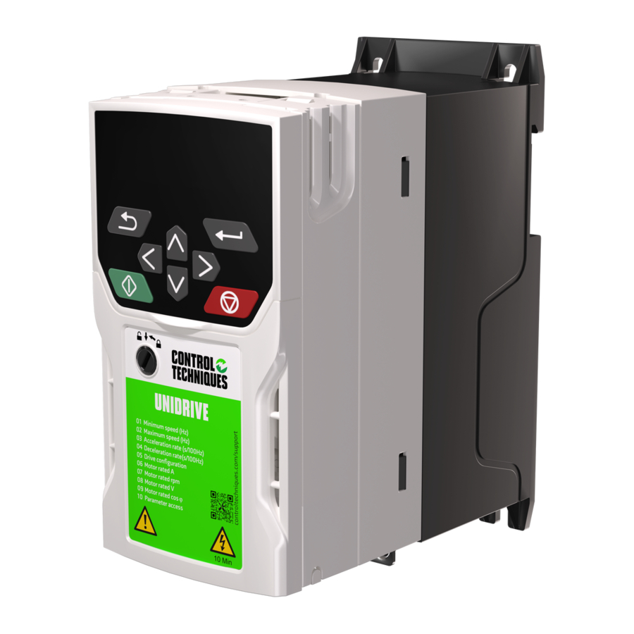
Optional LCD keypad and display The keypad and display provide information to the user regarding the operating status of the drive, alarms and trip codes, and provide the means for changing parameters, stopping and starting the drive, and the ability to perform a drive reset. Figure 5-1 Unidrive M400 keypad detail (1) The Enter button is used to enter parameter view or edit mode, or to accept a parameter edit. -
Page 26: Saving Parameters
Table 5-1 Status indications Upper row Drive output Description string stage The drive is inhibited and cannot be run. The Safe Torque Off Inhibit Disabled signals are not applied to the Safe Torque Off terminals is set to 0. The drive is ready to run. The drive enable is active, but the drive Ready Disabled inverter is not active because the final drive run is not active. -
Page 27: Basic Parameters (Menu 0)
Basic parameters (Menu 0) Menu 0 is used to bring together various commonly used parameters for basic easy set up of the drive. Menu 0: Basic parameters Range Default () () Parameter Type RFC-A RFC-A 00.001 Minimum Speed 0.00 to Pr 00.002 Hz 0.00 Hz RW Num 50Hz default: 50.00 Hz... - Page 28 Range Default () () Parameter Type RFC-A RFC-A Customer Defined 00.024 0.000 to 10.000 1.000 RW Num Scaling 00.025 User Security Code 0 to 9999 RW Num ND PT US Power-up Keypad 00.027 Control Mode Reset (0), Last (1), Preset (2) Reset (0) Reference Fast (0), Standard (1),...
- Page 29 Range Default () () Parameter Type RFC-A RFC-A Brake Controller 00.048 Brake Release 0.00 to 20.00 Hz 1.00 Hz RW Num Frequency Brake Controller 00.049 Brake Apply 0.00 to 20.00 Hz 2.00 Hz RW Num Frequency Brake Controller 00.050 0.0 to 25.0 s 1.0 s RW Num Brake Delay...
- Page 30 Range Default () () Parameter Type RFC-A RFC-A 00.086 Output Voltage 0 to 325 V or 0 to 650 V RO Num ND NC PT FI 00.087 Motor Rpm ±33000.0 rpm RO Num ND NC PT FI 00.088 Current Magnitude 0 to Drive Maximum Current A RO Num ND NC PT FI Torque Producing...
- Page 31 Unidrive M400 Quick Start Guide Issue Number: 8...
- Page 32 Figure 6-1 Menu 0 logic diagram Analog Input 1/ Forward Input 2 select Select Analog Input 1 Analog reference 00.016 00.094 Analog Analog Input 1 Input 1 Mode 00.093 Select Analog Input 2 Analog Input 2 00.095 01.050 01.015 01.050 >1 Bipolar Reference...
- Page 33 OL, RFC-A> AT ZERO TORQUE FREQUENCY FREQUENCY FORWARD REVERSE Analog outputs Digital output Reference On 00.091 Reverse Select 00.092 Final Demand Pre-ramp Reference Reference 00.083 00.082 Maximum Speed Ramp 00.002 Enable 00.029 Minimum Motor Parameters Speed Rated Current 00.006 00.001 Rated Speed 00.007 RFC-A mode only...
-
Page 34: Unidrive M400 Parameter Descriptions
Unidrive M400 parameter descriptions Key: Read / Read Number Binary Text string Filtered Write only parameter parameter parameter Protected Rating Power-down default User save DE Destination copied parameter dependent save value 00.001 Minimum Speed 0.00 to Pr 00.002 Hz 0.00 Hz RFC-A Set Pr 00.001 at the required minimum output frequency of the drive for both directions of rotation. - Page 35 00.004 Deceleration Rate 1 0.0 to 32000.0 s/100 Hz 10.0 s/100 Hz RFC-A Set Pr 00.004 at the required rate of deceleration. Note that larger values produce lower deceleration. The rate applies in both directions of rotation. 00.005 Drive Configuration AV (0), AI (1), AV Preset (2), AI Preset (3), Preset (4),...
- Page 36 00.006 Motor Rated Current Maximum Heavy 0.00 to Drive Rating A Duty Rating A RFC-A The rated current parameter must be set to the maximum continuous current of the motor (taken from the name plate). The motor rated current is used in the following: •...
- Page 37 00.010 User Security Status Level 1 (0), Level 2 (1), All Menus (2), Status Only (3), Level 1 (0) RFC-A No Access (4) This parameter controls access via the drive keypad as follows: Value Text Function Level 1 Access to first 10 parameters in Menu 0 only.
- Page 38 00.015 Jog Reference 0.00 to 300.00 Hz 1.50 Hz RFC-A Defines the reference when jog is enabled. 00.016 Analog Input 1 Mode 4-20 mA Stop (-6), 20-4 mA Stop (-5), 4-20 mA Low (-4), 20-4 mA Low (-3), 4-20 mA Hold (-2), ...
- Page 39 00.017 Bipolar Reference Enable Off (0) or On (1) Off (0) RFC-A Pr 00.017 determines whether the reference is uni-polar or bi-polar. See Minimum Speed (00.001). Allows negative speed reference in keypad mode. 00.018 to 00.021 Preset Reference 1 to 4 ...
- Page 40 00.025 User Security Code 0-9999 RFC-A If any number other than 0 is programmed into this parameter, user security can be applied so that no parameters except Pr 00.010 can be adjusted with the keypad. When this parameter is read via a keypad it appears as zero.
- Page 41 00.029 Ramp Enable RFC-A Off (0) or On (1) On (1) Setting Pr 00.029 to 0 allows the user to disable the ramps. This is generally used when the drive is required to closely follow a speed reference which already contains acceleration and deceleration ramps.
- Page 42 Value Text Description Coast Coast stop Ramp Ramp stop Ramp dc I Ramp stop + 1 second dc injection dc I Injection braking stop with detection of zero speed Timed dc I Timed injection braking stop Disable Disable No Ramp No ramp (RFC-A mode only) See the Control User Guide for further information.
- Page 43 00.034 Digital Input 5 Select Input (0), Therm Short Cct (1), Input (0) Thermistor (2), Therm No Trip (3) RFC-A This parameter selects the function of Digital Input 5 (terminal 14). Value Text Function Input Digital input Temperature measurement input with short circuit detection Therm Short Cct (Resistance <50 ) Temperature measurement input without short circuit detection but...
- Page 44 00.035 DO1 Control 0-21 RFC-A Defines the behaviour of digital output 1 (terminal 10). Value Description User defined by Digital IO1 Source/Destination A Drive running signal Frequency arrived signal Frequency level detection signal Frequency level detection signal Overload detection signal Power off state External fault stop Frequency upper limit...
- Page 45 00.036 Analog Output 1 Control 0 to 14 RFC-A Defines the functionality of Analog Output 1 (terminal 7). Value Description User defined by Analog Output 1 Source A Frequency output Frequency reference Motor speed Current Magnitude Torque output Torque current output Voltage output DC bus voltage (0~800 V)
- Page 46 00.038 Autotune 0 to 2 RFC-A 0 to 3 Defines the auto-tune test to be performed. There are two autotune tests available in open loop mode, a stationary and a rotating test. A rotating autotune should be used whenever possible so the measured value of power factor of the motor is used by the drive.
- Page 47 00.040 Number Of Motor Poles Auto (0) to 32 (16) Auto (0) RFC-A Set to the number of poles of the motor. The auto mode calculates the number of motor poles from the settings of Pr 00.007 and Pr 00.039. 00.041 Control Mode Ur S (0), Ur (1), Fixed (2),...
- Page 48 00.043 Serial Baud Rate 600 (1), 1200 (2), 2400 (3), 4800 (4), 9600 (5), 19200 (6), 38400 (7), 19200 (6) RFC-A 57600 (8), 76800 (9), 115200 (10) Defines the serial baud rate of the drive Changing the parameters does not immediately change the serial communications settings. See Reset Serial Communications (00.045) for more details.
- Page 49 00.047 Brake Controller Lower Current Threshold 0 to 200 % 10 % RFC-A Defines the lower current limit for the brake. See Brake Controller Brake Release in Parameter Reference Guide. 00.048 Brake Controller Brake Release Frequency 0.00 to 20.00 Hz 1.00 Hz RFC-A...
- Page 50 00.053 Brake Controller Initial Direction Ref (0), Forward (1), Reverse (2) Ref (0) RFC-A Defines the initial direction of the brake. Value Text Forward Reverse See Brake Controller Brake Release in Parameter Reference Guide. 00.054 Brake Controller Brake Apply Through Zero Threshold ...
- Page 51 00.056 to 00.058 Trip 0 to 2 0 to 255 RFC-A These parameters show the last 3 trips. 00.059 OUP Enable Stop (0) or Run (1) Run (1) RFC-A Enables the onboard user program. Onboard user programming provides a background task that loops continuously and a timed task that is executed each time at a defined rate.
- Page 52 00.066 Frequency Controller Integral Gain Ki1 RFC-A 0.00 to 655.35 s /rad 0.10 s /rad Defines the integral gain for frequency controller 1. See Frequency Controller Proportional Gain Kp1 (00.065). 00.067 Sensorless Mode Filter 4 (0), 5 (1), 6 (2), 8 (3), 12 (4), RFC-A 4 (0) ms 20 (5) ms...
- Page 53 00.072 PID1 Integral Gain 0.000 to 4.000 0.500 RFC-A Integral gain applied to the PID error. For further information, refer to the Parameter Reference Guide. 00.073 PID1 Feedback Invert Off (0) or On (1) Off (0) RFC-A This parameter allows the PID feedback source to be inverted.
- Page 54 00.077 Maximum Heavy Duty Rating 0.00 to Drive HD Current Rating A RFC-A Displays the maximum heavy duty current rating of the drive. 00.078 Software Version 0 to 99.99.99.99 RFC-A Displays the software version in the drive. 00.079 User Drive Mode Open loop (1)
- Page 55 00.083 Final Demand Reference -Pr 00.002 to Pr 00.002 or Pr 00.001 to Pr 00.002 Hz RFC-A Open loop mode: Final Demand Reference shows the fundamental drive output frequency from the Post Ramp Reference and the Hard Frequency Reference. RFC mode: Final Demand Reference shows the reference at the input to the frequency controller, which is the sum of the Post Ramp Reference, if the ramp output is not disabled and the hard frequency...
- Page 56 00.087 Motor Rpm ±33000.0 rpm RFC-A Motor Rpm = 60 x Frequency / Pole pairs where Pole pairs = the numeric value of Number Of Motor Poles (Pr 00.040) (i.e. 3 for a 6 pole motor) The frequency used to derive the Motor Rpm is the Final Demand Reference (Pr 00.083). 00.088 Current Magnitude ...
- Page 57 00.092 Reverse Select Off (0) or On (1) RFC-A Reverse Select, which is controlled by the drive sequencer, is used to invert Reference Selected (Pr 00.081) or the Jog Reference (Pr 00.015). 00.093 Jog Select Off (0) or On (1) RFC-A Jog Select, which is controlled by the drive sequencer, is used to select the Jog Reference (Pr 00.015).
-
Page 58: Running The Motor
Running the motor This section takes a new user through all the essential steps to running a motor for the first time. Table 7-1 Open Loop and RFC-A Action Detail Ensure: • The drive enable signal is not given, terminal 31 and 34 is open Before power up •... - Page 59 Ready to run The drive is now ready to run the motor. Close the Run Forward or Run Reverse terminals. Increasing and Changing the selected Analog frequency reference will decreasing speed increase and decrease the speed of the motor. To stop the motor by following the selected deceleration rate, open either the run forward or run reverse terminal.
-
Page 60: Diagnostics
Diagnostics Users must not attempt to repair a drive if it is faulty, nor carry out fault diagnosis other than through the use of the diagnostic features described in this chapter. If a drive is faulty, it must be returned to the supplier of the drive for repair. WARNING Table 8-1 Trip indications Trip code... - Page 61 Trip code Condition Description NV Media Card Trip; The voltage and / or current rating of the The current and / or voltage ratings are different Card Rating source and destination drives between source and destination drives. are different NV Media Card has the Read Attempt has been made to modify a read-only NV Media Card Read Only Only bit set...
- Page 62 Trip code Condition Description trip indicates a motor thermal overload based on the output current and motor thermal time constant. The drive will trip on Motor Too Hot when the accumulator gets to 100 %. Output current overload timed Motor Too Hot This can occur when: out (I •...
- Page 63 Trip code Condition Description The Over Volts trip indicates that the DC bus voltage has exceeded the maximum limit. Possible solutions: • Increase Deceleration Rate 1 (Pr 00.004) DC bus voltage has exceeded • Decrease the braking resistor value (staying above Over Volts the peak level or maximum the minimum value).
-
Page 64: Alarm Indications
Trip code Condition Description The Thermistor trip indicates that the motor thermistor Motor thermistor over- Thermistor connected to terminal 14 (digital input 5) on the control temperature connections has indicated a motor over temperature. The User OI ac trip is initiated if the output current of the User OI ac User OI ac drive exceeds the trip level set by User Over Current... -
Page 65: Nv Media Card Operation
NV Media Card Operation Figure 9-1 Installing the AI-Backup adaptor (SD Card) 1 1 1 Identify the two plastic fingers on the underside of the AI-Backup adaptor (1) - then insert the two fingers into the corresponding slots in the spring-loaded sliding cover on the top of the drive. Hold the adaptor firmly and push the spring loaded protective cover towards the back of the drive to expose the connector block (2) below. -
Page 66: Machine Control Studio
Machine Control Studio Machine Control Studio programming software powered by CODESYS Machine Control Studio software provides a flexible and intuitive environment for programming Unidrive M's new automation and motion control features. This new software offers programming for the Unidrive M400's onboard PLC. Machine Control Studio is powered by CODESYS, the leading open software for programmable machine control. -
Page 67: Ul Listing Information
UL listing information 11.1 UL file reference All models are UL Listed to both Canadian and US requirements. The UL file reference is: NMMS/ 7.E171230. 11.2 Option modules, kits and accessories Option Modules, Control Pods, Installation Kits and other accessories for use with these drives are UL Listed. -
Page 68: Motor Overload Protection And Thermal Memory Retention
BRANCH CIRCUIT PROTECTION The fuses and circuit breakers required for branch circuit protection are specified in the Installation Instructions. OPENING OF BRANCH CIRCUIT Opening of the branch-circuit protective device may be an indication that a fault has been interrupted. To reduce the risk of fire or electric shock, the equipment should be examined and replaced if damaged. - Page 70 Quick start setup using default parameter set Digital I/O Analog I/O 24 V user Analog input 1+ Frequency reference 1 Analog input 1- Digital I/O1 Zero frequency 10 V user Digital I/O 2 Unassigned Digital input 3 Analog input 2 Frequency Run forward reference 2...
Need help?
Do you have a question about the Unidrive M400 series and is the answer not in the manual?
Questions and answers