
Related Manuals for Dalsa Linea HS Series


Summary of Contents for Dalsa Linea HS Series
- Page 1 Linea HS Series Camera User’s Manual Monochrome, Color and Multifield TDI Line Scan sensors | cameras | frame grabbers | processors | software | vision solutions 03-032-20296-01 Revision 01 www.teledynedalsa.com...
- Page 2 All information provided in this manual is believed to be accurate and reliable. No responsibility is assumed by Teledyne DALSA for its use. Teledyne DALSA reserves the right to make changes to this information without notice. Reproduction of this manual in whole or in part, by any means, is prohibited without prior permission having been obtained from Teledyne DALSA.
-
Page 3: Table Of Contents
RAWINGS RECAUTIONS Electrostatic Discharge and the CMOS Sensor & C & S NSTALL ONFIGURE RAME RABBER OFTWARE Using Sapera CamExpert CamExpert Panes ETTING P FOR MAGING Camera I / O Connectors Linea HS Series Camera User's Manual Contents • 3... - Page 4 NHANCEMENT Black Level HANGING UTPUT ONFIGURATION Pixel Format IXEL LIGNMENT Red Shift X and Y & R AVING ESTORING AMERA ETUP ONFIGURATIONS Active Settings for Current Operation User Setting Factory Settings 4 • Contents Linea HS Series Camera User's Manual...
- Page 5 Power Supply Issues Causes for Overheating & Power Shut Down DECLARATIONS OF CONFORMITY FCC Statement of Conformance CE and UKCA Declaration of Conformity DOCUMENT REVISION HISTORY CONTACT INFORMATION ALES NFORMATION ECHNICAL UPPORT Linea HS Series Camera User's Manual Contents • 5...
-
Page 6: Figures
Figure 47: Align Red X Shift and Align Red Y Shift Figure 48: Effect of Align Red X / Y Shift Settings Figure 49. Relationship Between Camera Settings Figure 50 Example CamExpert Camera Information Panel Figure 51: CamExpert Power-Up Configuration Dialog 6 • Contents Linea HS Series Camera User's Manual... - Page 7 Figure 58: File Upload Completed Message Box Figure 59: Transport Layer Panel Figure 60: Acquisition & Transfer Control Panel Figure 61: CamExpert Voltage & Temperature Features Figure 62: CamExpert Test Pattern Feature Linea HS Series Camera User's Manual Contents • 7...
-
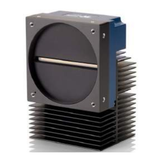
Page 8: Linea Hs Series Cameras
(CX4 or LC connector). Teledyne DALSA’s Linea HS cameras and compatible frame grabbers combine to offer a complete solution for the next generation of automatic optical inspection systems. This camera is recommended for detecting small defects at high speeds and over a large field of view in LCD and OLED flat panel displays, DNA sequencing, printed circuit boards, film and large format web materials. -
Page 9: Color And Multifield Technology
Multifield is a new imaging technology that enables capturing multiple images using various lighting conditions (for example, brightfield, darkfield and backlight) in a single scan. Teledyne DALSA’s Linea HS multifield camera is the first product in the industry capable of capturing up to three images using light sources at different wavelengths. -
Page 10: Camera Highlights
Applications • Flat panel LCD and OLED display inspection • Web inspection • Printed circuit board inspection • Pathology • DNA sequencing • High throughput and high-resolution applications 10 • Linea HS Series Cameras Linea HS Series Camera User's Manual... -
Page 11: Part Numbers And Software Requirements
5.0 x 5.0 µm Camera Link HS pixels Multifield HL-HF-16K13T-00-R 16,384 x (64 + 128 + 64) 130 kHz x 3 5.0 x 5.0 µm Camera Link HS pixels Linea HS Series Camera User's Manual Linea HS Series Cameras • 11... - Page 12 GenICam™ support (XML camera description file) Embedded within camera Sapera LT, including CamExpert GUI application and GenICam for Camera Link Latest version on the imaging driver Teledyne DALSA Web site 12 • Linea HS Series Cameras Linea HS Series Camera User's Manual...
-
Page 13: Specifications
DSNU (FPN) < ±2 DN Integral non-linearity < 2% Calibration at 80% saturation, measurements at 50% saturation Light sources vary spectrally and spatially: re-calibrate cameras in actual system Linea HS Series Camera User's Manual Linea HS Series Cameras • 13... -
Page 14: Monochrome 300Khz Models
150 kHz 150 kHz x 2 (HDR) 150 kHz x 2 (HDR) 150 kHz x 2 (HDR) Line rate, min 10 kHz Bit Depth 8-bit or 12-bit selectable 14 • Linea HS Series Cameras Linea HS Series Camera User's Manual... - Page 15 0.5 nJ/cm At 670 nm 0.4 pJ/cm At 670 nm Random Noise below quantization limit cannot be measured accurately; use higher bit depth or higher gain for comparison purposes Linea HS Series Camera User's Manual Linea HS Series Cameras • 15...
-
Page 16: Monochrome 400Khz Models
< 0.4 pJ/cm < 0.4 pJ/cm At 670 nm Random Noise below quantization limit cannot be measured accurately; use higher bit depth or higher gain for comparison purposes 16 • Linea HS Series Cameras Linea HS Series Camera User's Manual... -
Page 17: Color And Multifield Models
Red 0.3 pJ/cm Red 0.3 pJ/cm At 660 nm Random Noise below quantization limit cannot be measured accurately; use higher bit depth or higher gain for comparison purposes Linea HS Series Camera User's Manual Linea HS Series Cameras • 17... -
Page 18: Super Resolution Monochrome Model
Environmental Specifications Storage temperature range -20 °C to +80 °C Humidity (storage and operation) 15% to 85% relative, non-condensing MTBF (mean time between failures) >100,000 hours, typical field operation 18 • Linea HS Series Cameras Linea HS Series Camera User's Manual... -
Page 19: Flash Memory Size
Flash memory size All models 4 GByte Certification & Compliance Table 11: Camera Certification & Compliance Compliance See the Declarations of Conformity section at the end of this manual. Linea HS Series Camera User's Manual Linea HS Series Cameras • 19... -
Page 20: Specifications: Monochrome Models
The following graphs show the spectral Responsivity and QE from the main array (128 stages), in 8-bit, for 4k and 8k camera models. Figure 1: 4k & 8K Monochrome Models Spectral Responsivity & QE 20 • Linea HS Series Cameras Linea HS Series Camera User's Manual... -
Page 21: Figure 2: 13K And 16K Monochrome Models Spectral Responsivity & Qe
The following graphs show the spectral Responsivity and QE from the main array (128 stages), in 8-bit, for 13k and 16k camera models. Figure 2: 13k and 16K Monochrome Models Spectral Responsivity & QE Linea HS Series Camera User's Manual Linea HS Series Cameras • 21... -
Page 22: Camera Input Power
Figure 3: Standard 4k and 8k Models Power vs. Input Voltage Figure 4: Standard 13k and 16k Models Power Vs. Input Voltage Test conditions: Max line rate for model, TDI Mode—128, Bit Mode—8, Black Level—31, Temperature—Ambient 22 • Linea HS Series Cameras Linea HS Series Camera User's Manual... -
Page 23: Figure 5. Hl-Hm-16K40H-00-R Power Vs. Input Voltage
The following graphs detail the power vs. input voltage for the HL-HM-16K40H-00-R Figure 5. HL-HM-16K40H-00-R Power Vs. Input Voltage Test conditions: Max line rate—400 kHz, TDI Mode—128, Bit Mode—8, Black Level—31, Temperature—Ambient Linea HS Series Camera User's Manual Linea HS Series Cameras • 23... -
Page 24: Specifications: Color Model
The following graphs show the spectral Responsivity and QE, 8-bit, 1x gain. Figure 6: Color Model Spectral Responsivity and QE Camera Input Power The following graph details the power vs. input voltage for the camera. 24 • Linea HS Series Cameras Linea HS Series Camera User's Manual... -
Page 25: Figure 8: Color Model Power Vs. Input Voltage
Figure 7: Color Model Power Vs. Input Voltage Test conditions: Max line rate—300 kHz, Bit Mode—8, Black Level—31, Temperature—Ambient Linea HS Series Camera User's Manual Linea HS Series Cameras • 25... -
Page 26: Specifications: Multifield Model
The following specifications apply to the multifield Linea HS model: • HL-HF-16K13T Responsivity & QE The following graphs show the spectral Responsivity and QE, 8-bit, 1x gain. Figure 8: Multifield Model Spectral Responsivity 26 • Linea HS Series Cameras Linea HS Series Camera User's Manual... -
Page 27: Camera Input Power
The following graph details the power vs. input voltage for the camera. Figure 10: Multifield Model Power Vs. Input Voltage Test conditions: Max line rate—300 kHz, Bit Mode—8, Black Level—31, Temperature—Ambient Linea HS Series Camera User's Manual Linea HS Series Cameras • 27... -
Page 28: Specifications: Super Resolution 32K Model
The following graphs show the spectral responsivity and QE in 32k super resolution mode; for 16k modes, multiply responsivity values by 2. Figure 11: Super Resolution Model Spectral Responsivity & QE, 32k SR Mapped, 1x gain 28 • Linea HS Series Cameras Linea HS Series Camera User's Manual... -
Page 29: Camera Input Power
The following graphs detail the power vs. input voltage for the HL-HM-32K40S-00-R Figure 12. Super Resolution Model Power Vs. Input Voltage Test conditions: Max line rate—300 kHz, TDI Mode—128, Bit Mode—8, Black Level—31, Temperature—Ambient Linea HS Series Camera User's Manual Linea HS Series Cameras • 29... -
Page 30: Linea Hs Dark Current
• Increases exponentially with temperature, doubling approximately every 7°C. For best performance Teledyne DALSA recommends recalibrating the dark flat field coefficients (FPN) at a stable operating temperature; for more information of flat field correction, refer to the Image Response Uniformity & Flat Field Calibration section. -
Page 31: Figure 15. Line Period Vs. Dark Signal
Figure 14. Line Period vs. Dark Signal Linea HS Series Camera User's Manual Linea HS Series Cameras • 31... -
Page 32: Camera Processing Chain
GenApi module of the GenICam specification. The camera uses the GenICam Generic Control Protocol (GenCP V1.0) to communicate over the Camera Link HS command lane. For more information see www.genicam.org. 32 • Linea HS Series Cameras Linea HS Series Camera User's Manual... -
Page 33: Camera Link Hs
Data and command transmission are done with CLHS X protocol (64b / 66b) at the default speed of 10 Gbps. Note: high speed data transmission limits the effective distance of copper-based cables. Linea HS Series Camera User's Manual Linea HS Series Cameras • 33... -
Page 34: Data Cables
Recommended fiber optic cables are types OM3 and OM4. OM4 is used for distances > 300 m, but also requires SFP+ transceiver module changes. Contact Teledyne DALSA Support for more information on recommended cables. Table 12: LC Fiber Optic Cable Details... - Page 35 Camera Link HS cables can be bought from an OEM. OEM cables are also available for applications where flexing is present. Please refer to Teledyne DALSA’s website (www.teledynedalsa.com) for a list of recommended cable vendors and for part numbers.
-
Page 36: Mechanical Drawings
Mechanical Drawings Figure 18:HL-FM-04K30H-00-R and HL-FM-08K30H-00-R Mechanical Drawing 36 • Linea HS Series Cameras Linea HS Series Camera User's Manual... -
Page 37: Figure 20: Hl-Hm-08K30H-00-R And Hl-Hm-08K40H-00-R Mechanical Drawing
Figure 19: HL-HM-08K30H-00-R and HL-HM-08K40H-00-R Mechanical Drawing Linea HS Series Camera User's Manual Linea HS Series Cameras • 37... -
Page 38: Figure 21: Hl-Fm-13K18H-00-R And Hl-Fm-16K15A-00-R Mechanical Drawing
Figure 20: HL-FM-13K18H-00-R and HL-FM-16K15A-00-R Mechanical Drawing 38 • Linea HS Series Cameras Linea HS Series Camera User's Manual... - Page 39 Figure 21: HL-HM-13K30H-00-R, HL-HM-16K30H-00-R, HL-HM-16K40H-00-R and HL-HF-16K10T-00-R Mechanical Drawing Linea HS Series Camera User's Manual Linea HS Series Cameras • 39...
-
Page 40: Precautions
(ESD). Electrostatic charge introduced to the sensor window surface can induce charge buildup on the underside of the window. The charge normally dissipates within 24 hours and the sensor returns to normal operation. 40 • Linea HS Series Cameras Linea HS Series Camera User's Manual... -
Page 41: Install & Configure Frame Grabber & Software
Install & Configure Frame Grabber & Software Because of the high bandwidth of these cameras, a compatible Teledyne DALSA frame grabber (Xtium2-CLHS PX8 (OR-A8S0-PX870)), or equivalent, is recommended. The frame grabber requirements for the 8K and 16K camera differ. Follow the manufacturer’s installation instructions. -
Page 42: Camexpert Panes
This avoids confusion by eliminating parameter choices when they do not apply to the hardware in use. Display pane: Provides a live or single frame acquisition display. Frame buffer parameters are shown in an information bar above the image window. 42 • Linea HS Series Cameras Linea HS Series Camera User's Manual... - Page 43 Output Message Pane: Displays messages from CamExpert or the device driver. At this point you are ready to start operating the camera, acquire images, set camera functions and save settings. Linea HS Series Camera User's Manual Linea HS Series Cameras • 43...
-
Page 44: Setting Up For Imaging
Adjust the supply to ensure that it reads above or equal to 12 V. Note: If your power supply does not meet these requirements, then the camera performance specifications are not guaranteed. 44 • Linea HS Series Cameras Linea HS Series Camera User's Manual... -
Page 45: Power And Gpio Connections
Note: intended as a return path for GPIO signal and not intended as a power ground Signal Ground Note: intended as a return path for GPIO signal and not intended as a power ground Linea HS Series Camera User's Manual Linea HS Series Cameras • 45... - Page 46 Stress or vibration of the heavy CLHS AOC cables may damage the camera’s connectors. 46 • Linea HS Series Cameras Linea HS Series Camera User's Manual...
-
Page 47: Figure 26: Gpio Cable Accessory #Cr-Genc-Iop00
Mating GPIO Cable Assembly An optional GPIO breakout cable (12-pin Female Hirose to 13-Pos Euro Block) is available for purchase from Teledyne DALSA under accessory number #CR-GENC-IOP00 to order. Figure 25: GPIO cable accessory #CR-GENC-IOP00 Linea HS Series Camera User's Manual... -
Page 48: Establishing Camera Communications
Please refer to the frame grabber user’s documentation for further details on selection input and output pixel formats. 48 • Linea HS Series Cameras Linea HS Series Camera User's Manual... -
Page 49: Establishing Data Integrity
If the test pattern is not correct, check the cable connections and the frame grabber setup. • Disable the test pattern output. Linea HS Series Camera User's Manual Linea HS Series Cameras • 49... -
Page 50: Camera Performance And Features
(compression in the scan direction) of the image data. When the line rate returns to or below the maximum specified, then normal imaging will be reestablished. 50 • Camera Performance and Features Linea HS Series Camera User's Manual... -
Page 51: Measuring Line (Trigger) Rate
(3 sensor colors output) (2 sensor colors output) (1 sensor color output) 8-bit 12-bit 8-bit 12-bit 8-bit 12-bit HL-HF-16K13T-00-R 100 kHz 76 kHz* 150 kHz 115 kHz* 300 kHz 230 kHz* Linea HS Series Camera User's Manual Camera Performance and Features • 51... -
Page 52: Minimum Line Rate
Whether the scan direction is set correctly can easily be seen in live imaging. An image will appear “normal”, sharp and focused. If the optical setup is not properly focused, blur will occur in both, horizontal (cross-scan) and vertical (in-scan), directions. 52 • Camera Performance and Features Linea HS Series Camera User's Manual... -
Page 53: Figure 27. Image With Incorrect Scan Direction
If blur occurs only in scan direction (see below), the scan direction is set incorrectly. Figure 26. Image with incorrect scan direction Linea HS Series Camera User's Manual Camera Performance and Features • 53... -
Page 54: Camera Orientation
TDI sensor before the direction is changed. This ensures that valid data will be generated on the return path as the camera’s field of view reaches the area to be inspected. 54 • Camera Performance and Features Linea HS Series Camera User's Manual... -
Page 55: Spatial Correction
Main Array Output 1 + n = Secondary Array Line Output 1 Figure 28: Spatial Correction Teledyne DALSA Xtium CLHS frame grabbers automatically perform spatial correction for Linea HS cameras. The camera ensures the scan direction alignment of the lines by delaying the image data for each row a set amount of time, as dictated by the scan direction. -
Page 56: Figure 30. Standard And High-Speed Camera Line Spacing - Forward Scan Direction
128 Lines 5 µm pixel 175 µm gap equivalent to 35 lines Readout 64 Lines 5 µm pixel Figure 29. Standard and High-Speed Camera Line Spacing – Forward Scan Direction 56 • Camera Performance and Features Linea HS Series Camera User's Manual... -
Page 57: Figure 31. Standard And High-Speed Camera Line Spacing - Reverse Scan Direction
128 Lines 5 µm pixel Readout 175 µm gap equivalent to 35 lines 64 Lines 5 µm pixel Readout Figure 30. Standard and High-Speed Camera Line Spacing – Reverse Scan Direction Linea HS Series Camera User's Manual Camera Performance and Features • 57... -
Page 58: Figure 32. Multifield Camera Line Spacing - Forward Scan Direction
35 lines Readout 128 Lines 5 µm pixel gap of 35 lines Readout 64 Lines 5 µm pixel Figure 31. Multifield Camera Line Spacing – Forward Scan Direction 58 • Camera Performance and Features Linea HS Series Camera User's Manual... -
Page 59: Figure 33. Standard And High-Speed Camera Line Spacing - Reverse Scan Direction
128 Lines 5 µm pixel Readout gap of 35 lines 64 Lines 5 µm pixel Readout Figure 32. Standard and High-Speed Camera Line Spacing – Reverse Scan Direction Linea HS Series Camera User's Manual Camera Performance and Features • 59... -
Page 60: Figure 34. Super Resolution Camera Line Spacing - Forward Scan Direction
Readout 128 Lines 5 µm pixel 81.923 mm 35 line gap Readout 64 Lines 5 µm pixel Figure 33. Super Resolution Camera Line Spacing – Forward Scan Direction 60 • Camera Performance and Features Linea HS Series Camera User's Manual... -
Page 61: Figure 35. Super Resolution Camera Line Spacing - Reverse Scan Direction
128 Lines 5 µm pixel Readout 81.923 mm 35 line gap 64 Lines 5 µm pixel Readout Figure 34. Super Resolution Camera Line Spacing – Reverse Scan Direction Linea HS Series Camera User's Manual Camera Performance and Features • 61... -
Page 62: Alignment Markers
TDI operation; misaligned columns can result in blurred or smeared images. When enabled, alignment markers are displayed as graphic overlays in the image output. Figure 35: Alignment Markers 62 • Camera Performance and Features Linea HS Series Camera User's Manual... -
Page 63: Parallax Correction: Using The Camera At Non-Perpendicular Angles To The Object
Selection of the arrays to adjust is dependent on positive or negative angle; it is not sensitive to scan direction. Camera at angle stretches more distant array outputs Projected color filters @ object plane Figure 36: Camera Angle Parallax Linea HS Series Camera User's Manual Camera Performance and Features • 63... -
Page 64: Figure 38: Parallax Effect On Sensor Arrays Output
Note: Parallax correction of the individual arrays cannot be performed due to the row summing in the sensor. Therefore, at high angles, a degradation in MTF at the end pixels may occur. 64 • Camera Performance and Features Linea HS Series Camera User's Manual... -
Page 65: Imaging Modes
64, 16 (not used) It is important to execute flat field correction based on the number of stages in the final application, since pixel behavior changes with stage selection. Linea HS Series Camera User's Manual Camera Performance and Features • 65... -
Page 66: High Dynamic Range (Hdr)
The multifield TDI modes allow the output of any combination of the three color arrays; single colors only (R, G or B), color pairs (RG, RB or GB) or all three colors (RGB). 66 • Camera Performance and Features Linea HS Series Camera User's Manual... -
Page 67: 32K Super Resolution Modes
Full Well, higher SNR and lower noise. This mode provides the lowest level of data processing in the Teledyne DALSA system and hence poses the lowest risk of affecting subsequent user data processing. -
Page 68: Internal Trigger Mode
Table 30: Super Resolution Model Internal Trigger Rate Features TDI Mode Trigger Rate Feature Maximum 32k Modes AcquisitionLineRate 150 kHz 16k TDI AcquisitionLineRate 300 kHz Area AcquisitionFrameRate 2 kHz Multi Area AcquisitionFrameRate 650 Hz 68 • Camera Performance and Features Linea HS Series Camera User's Manual... -
Page 69: Establishing The Optimal Response
Output Strobe Control Example Camera Trigger Trigger Delay Sensor Trigger Output Line Output Duration 3,4,5 or 6 Output Delay Set to Trigger Delay + 1.6 µs Figure 38: Strobe Timing Linea HS Series Camera User's Manual Camera Performance and Features • 69... - Page 70 In addition, an Exposure Active signal is generated and can be supplied to any of the GPIO outputs. This allows triggering or timing external light sources. The following diagram illustrates the logical control signal flow in the Linea HS series camera family.
-
Page 71: Figure 40 Gpio Functionality Block Diagram
GPIO Connector Output Line Invert Output Duration Output Delay Output Line 5 Output Line 6 Output Line Invert Output Duration Output Delay Figure 39 GPIO functionality block diagram Linea HS Series Camera User's Manual Camera Performance and Features • 71... -
Page 72: Image Response Uniformity & Flat Field Calibration
DN level for flat field calibration. Once complete, return the exposure time to its original setting. 72 • Camera Performance and Features Linea HS Series Camera User's Manual... -
Page 73: Saving & Loading A Prnu Set Only
The PRNU coefficients are used by the camera as soon as they are uploaded. To avoid loss at power up or while changing row settings, the uploaded coefficients should be saved to one of the available user sets. Linea HS Series Camera User's Manual Camera Performance and Features • 73... -
Page 74: Flat Field Calibration Filter
Once set, another ROI can be defined and flat field calibrated. 74 • Camera Performance and Features Linea HS Series Camera User's Manual... -
Page 75: Image Filters
If the contrast is below the set value, then the pixel filter is applied. A value of 0 will turn off the filters for all pixels and a value of 1 will keep the filter on for all pixels. Linea HS Series Camera User's Manual Camera Performance and Features • 75... -
Page 76: Binning
Note: Binning parameters can only be changed when image transfer to the frame Acquisition and Transfer Control Category grabber is stopped. Refer to the the appendix for details on stopping and starting the acquisition. 76 • Camera Performance and Features Linea HS Series Camera User's Manual... -
Page 77: Using Area Of Interest (Aois)
AOI, it will be able to extract and process each individual AOI from the single larger image. HL-HM- Note: AOIs are not supported by the Linea HS 32k Super Resolution model ( 32K15S-00-R). Linea HS Series Camera User's Manual Camera Performance and Features • 77... -
Page 78: Steps To Setup Area Of Interest
If the AOI count is reduced to less than the current AOI count, the AOI selector will be changed to the largest of the new AOI count available. 78 • Camera Performance and Features Linea HS Series Camera User's Manual... -
Page 79: Enhancement Of Interest (Eois) Regions
Alternatively, EOIs provide the maximum line rate but with a flattened image region. Note: EOI parameter settings are not stored in the camera and are erased at camera reset. Linea HS Series Camera User's Manual Camera Performance and Features • 79... -
Page 80: Customized Linearity Response (Lut)
Look Up Table to upload a file. The file format is described in 03-084-20133 Linea Binary File Format which can be obtained from Teledyne DALSA Technical Support. This document also includes Excel spreadsheet examples. 80 • Camera Performance and Features... -
Page 81: How To Generate Lut With Camexpert
3. Under Board select Basic Timing and set Pixel Depth to 12. 4. Under Board, select Image Buffer and ROI and set Image Buffer Format to Monochrome 16 bits. 5. Leave Image Buffer and ROI selected. Linea HS Series Camera User's Manual Camera Performance and Features • 81... - Page 82 7. In the Lookup Table dialog, select the output LUT by scrolling through the different options under Value and configure any required parameters (for example, Gamma correction requires a Correction factor). 82 • Camera Performance and Features Linea HS Series Camera User's Manual...
-
Page 83: Adjusting Responsivity And Contrast Enhancement
1 to ~4x. System Gain can be adjusted from 1 to 10x. When an image contains no useful dark image data below a specific threshold, then it may be beneficial to increase the contrast of the image. Linea HS Series Camera User's Manual Camera Performance and Features • 83... -
Page 84: Black Level
In Image Format category, set Pixel Format to Mono 12 (or BGR 12 if supported). In the host frame grabber configuration, set Pixel Depth to 12. In Acquisition and Transfer Control category, set Start Acquisition. 84 • Camera Performance and Features Linea HS Series Camera User's Manual... -
Page 85: Red Pixel Alignment
Align Red X Shift Align Red Y Shift features to fine-tune the correction (default = 0.5). The necessary values depend on the sensor direction and the target scene. Linea HS Series Camera User's Manual Camera Performance and Features • 85... -
Page 86: Red Shift X And Y
Adjust Y and maintain X shifts vertically (up / down). • Adjust both X and Y shifts diagonally. Figure 46: Align Red X Shift and Align Red Y Shift 86 • Camera Performance and Features Linea HS Series Camera User's Manual... -
Page 87: Figure 48: Effect Of Align Red X / Y Shift Settings
Align Red Shift X = 0.5, Align Red Shift Y = 0.5 Align Red Shift X = 0.5, Align Red Shift Y = 0.8 (default values) Figure 47: Effect of Align Red X / Y Shift Settings Linea HS Series Camera User's Manual Camera Performance and Features • 87... -
Page 88: Saving & Restoring Camera Setup Configurations
( Saves Automatically ) ( Saves Automatically ) By GenIcam Command 1 . Select a ‘User Set’ 2 . Initiate a ‘User Set Save’ Figure 48. Relationship Between Camera Settings 88 • Camera Performance and Features Linea HS Series Camera User's Manual... -
Page 89: Active Settings For Current Operation
The chosen set automatically becomes the default setting and is the set loaded when the camera is reset or powered up. Linea HS Series Camera User's Manual Camera Performance and Features • 89... -
Page 90: Appendix A: Genicam Commands
Additionally, the Device Version column will indicate which parameter is a member of the DALSA Features Naming Convention (using the tag DFNC), versus the GenICam Standard Features Naming Convention (SFNC tag not shown). -
Page 91: Camera Information Category
Determine the status of the device using the ‘Built-In Self Beginner Test’ (BIST). Possible return values are device-specific. (RO) DFNC for status code details. Built-In Self-Test Codes Linea HS Series Camera User's Manual Appendix A: GenICam Commands • 91... - Page 92 Power-up Configuration. Select the user defined configuration UserSet 12 as the UserSet12 UserSet12 Power-up Configuration. UserSet13 UserSet13 Select the user defined configuration UserSet 13 as the Power-up Configuration. 92 • Appendix A: GenICam Commands Linea HS Series Camera User's Manual...
- Page 93 UserSet13 UserSet13 Select the User-defined Configuration space UserSet13 to save to or load from features settings previously saved by the user. Linea HS Series Camera User's Manual Appendix A: GenICam Commands • 93...
-
Page 94: Built-In Self-Test Codes (Bist)
The first drop list selects the camera configuration set to load on power-up (see feature UserSetDefaultSelector). The user chooses the factory data set or from one of 16 available user- saved states. 94 • Appendix A: GenICam Commands Linea HS Series Camera User's Manual... -
Page 95: User Set Configuration Management
Load. To save a current camera configuration, select User Set 1 to 16 and click Save. Select a saved user set and click Load to restore a saved configuration. Linea HS Series Camera User's Manual Appendix A: GenICam Commands • 95... -
Page 96: Camera Control Category
Press to show the current line rate provided to the camera Beginner Measured Line by either internal or external sources DFNC Rate Acquisition AcquisitionFrameRate Displays the camera frame rate, in Hx. Beginner Frame Rate 96 • Appendix A: GenICam Commands Linea HS Series Camera User's Manual... - Page 97 Vertically align red pixels with green and blue Align Red alignRedThreshold Specifies the threshold to use for processing red pixels; the Beginner Threshold higher the value, the more pixels processed. DFNC Linea HS Series Camera User's Manual Appendix A: GenICam Commands • 97...
- Page 98 Executes the automatic white balance function. This Beginner Auto calculates the RGB gain adjustments to bring the average of each color up to the average of the brightest color. (Multifield color model only) 98 • Appendix A: GenICam Commands Linea HS Series Camera User's Manual...
- Page 99 Captures the current line and saves it to the cameras Flash Beginner Flash memory as a TIFF file that can be retrieved using the File DFNC Access Control Features. (Multifield color model only) Linea HS Series Camera User's Manual Appendix A: GenICam Commands • 99...
-
Page 100: Digital Io Control Category
(after any processing by the line inverter module). Falling Edge FallingEdge The trigger is considered valid on the falling edge. Any Edge AnyEdge The trigger is considered valid on any edge. 100 • Appendix A: GenICam Commands Linea HS Series Camera User's Manual... - Page 101 Line Inverter LineInverter Controls whether to invert the polarity of the Beginner selected input or output line signal. The line signal is not inverted. The line signal is inverted. Linea HS Series Camera User's Manual Appendix A: GenICam Commands • 101...
- Page 102 Refresh Line Status refreshLineStatus Update the LineStatus feature Beginner DFNC Line Status LineStatus Returns the current state of the GPIO line selected Expert with the LineSelector feature. (RO) 102 • Appendix A: GenICam Commands Linea HS Series Camera User's Manual...
-
Page 103: Flat Field Category
Beginner DFNC FPN and PRNU correction disabled. FPN and PRNU correction enabled. Clear Coefficents flatfieldCalibrationClearCoefficient Reset all FPN to 0 and all PRNU Beginner coefficients to 1. DFNC Linea HS Series Camera User's Manual Appendix A: GenICam Commands • 103... - Page 104 Factory or User set. Save Calibration flatfieldCalibrationSave Saves the User PRNU set specified by Guru flatfieldCorrectionCurrentActiveSet to the DFNC camera. 104 • Appendix A: GenICam Commands Linea HS Series Camera User's Manual...
-
Page 105: Image Filter Mode
Possible values range from -127 to 127. DFNC EOI Gain enhancedImageGain Set the gain to apply to the EOI. Possible values range from 0.011 to 3.99, in increments of 0.000001. Linea HS Series Camera User's Manual Appendix A: GenICam Commands • 105... -
Page 106: Image Format Control Category
Read only. Binning Horizontal BinningHorizontal Number of horizontally adjacent pixels to sum Beginner together. This increases the intensity of the pixels and reduces the horizontal resolution of the image. 106 • Appendix A: GenICam Commands Linea HS Series Camera User's Manual... - Page 107 PRNU file using the FileAccess > Miscellaneous > User PRNU feature. The PRNU coefficient will be applied to a midscale (128 DN) test image. Contact Teledyne DALSA support for an Excel file that can help with this. AOI Count multipleROICount Specifies the number of AOIs output.
- Page 108 Black Size of the image input pixels, in bits per pixel. Input Pixel Size pixelSizeInput DFNC (RO) Invisible Sensor input data path is 12-bits per pixel. 12-bits/Pixel Bpp12 108 • Appendix A: GenICam Commands Linea HS Series Camera User's Manual...
-
Page 109: File Access Control Category
Select the Open operation - executed by FileOperationExecute. Close Close Select the Close operation - executed by FileOperationExecute. Read Read Select the Read operation - executed by FileOperationExecute. Linea HS Series Camera User's Manual Appendix A: GenICam Commands • 109... - Page 110 For Read or Write operations, the number of successfully Guru Result read/written bytes is returned. (RO) File Size FileSize Represents the size of the selected file in bytes. Guru 110 • Appendix A: GenICam Commands Linea HS Series Camera User's Manual...
-
Page 111: File Access Via The Camexpert Tool
Figure 57: File Upload Completed Message Box Caution: Do not interrupt the file transfer by powering down the camera or closing CamExpert. Linea HS Series Camera User's Manual Appendix A: GenICam Commands • 111... -
Page 112: Clhs File Transfer Protocol
Set the FileOperationSelector to Close • Close the file by setting FileOperationExecute to 1 and poll until 0 and complete • Read FileOperationStatus to confirm the close worked 112 • Appendix A: GenICam Commands Linea HS Series Camera User's Manual... -
Page 113: Upload File To Camera
In the “Type” drop down box select “Miscellaneous.” • In the “File selector” drop down box select “CameraData.” • Hit “Download” • Save the text file and send the file to Teledyne DALSA customer support. Linea HS Series Camera User's Manual Appendix A: GenICam Commands • 113... -
Page 114: Transport Layer Control Category
If a feature read or write returns that it fails, read Beginner this feature to get the actual reason for the failure DFNC Returns the last error. Reading this feature clears it. Sapera only. 114 • Appendix A: GenICam Commands Linea HS Series Camera User's Manual... - Page 115 Refresh CLHS 8b/10b Guru clhsErrorCountRefresh Refresh the selected clhsErrorCount value. Receive Error Count DFNC Reset Receive Error clhsErrorCountReset Reset the selected clhsErrorCount Guru value to 0. Count DFNC Linea HS Series Camera User's Manual Appendix A: GenICam Commands • 115...
-
Page 116: Acquisition And Transfer Control Category
(WO) Acquisition Status AcquisitionStatus Reads the acquisition state. Beginner Acquiring Acquiring Currently acquiring and sending image data. Not Acquiring NotAcquiring Currently not acquiring or sending image data. 116 • Appendix A: GenICam Commands Linea HS Series Camera User's Manual... -
Page 117: Appendix B: Trouble Shooting Guide
The camera data file includes the operational configuration and status of the camera This text file can be downloaded from the camera and forwarded to Teledyne DALSA Technical Customer support team to aid in diagnosis of any reported issues. See the Saving & Restoring Camera Setup Configurations section for details on downloading the Camera Data file. - Page 118 PRNU coefficients that appropriately manipulate the half scale data to achieve the desired pattern. See section Setting Custom Flat Field Coefficients for details. 118 • Appendix B: Trouble Shooting Guide Linea HS Series Camera User's Manual...
- Page 119 Hardware is good, but the CLHS connection has not been established or has been broken. Constant Green The CLHS Link has been established and data transfer may begin Linea HS Series Camera User's Manual Appendix B: Trouble Shooting Guide • 119...
-
Page 120: Resolving Camera Issues
See the Xtium2-CLHS frame grabber user manual for details. c. Do the encoder signal levels conform to the requirements outlined in the Xtium2- CLHS frame grabber user manual? 120 • Appendix B: Trouble Shooting Guide Linea HS Series Camera User's Manual... -
Page 121: Image Quality Issues
Note: Dust accumulation on the lens will not cause vertical lines. However, a heavy accumulation of dust on the lens will eventually degrade the camera’s responsivity and focus quality. Linea HS Series Camera User's Manual Appendix B: Trouble Shooting Guide • 121... - Page 122 The diagrams in the user manual take the lens effect into account. 122 • Appendix B: Trouble Shooting Guide Linea HS Series Camera User's Manual...
- Page 123 Only when all rows being accumulated have received the same image will the output be correct. Prior to this some lines have been exposed to one direction and other lines exposed to the opposite direction in the accumulated output. Linea HS Series Camera User's Manual Appendix B: Trouble Shooting Guide • 123...
-
Page 124: Power Supply Issues
The camera will also protect against the accidental application of a reverse input supply up to a maximum of -30 V. Beyond this voltage, the camera may be damaged. 124 • Appendix B: Trouble Shooting Guide Linea HS Series Camera User's Manual... -
Page 125: Causes For Overheating & Power Shut Down
The only means to recover from a thermal shutdown is to turn the camera’s power off. Once the camera has cooled down, the camera data can be restored by reapplying power to the camera. Linea HS Series Camera User's Manual Appendix B: Trouble Shooting Guide • 125... -
Page 126: Declarations Of Conformity
This equipment is intended to be a component of a larger industrial system. CE and UKCA Declaration of Conformity Teledyne DALSA declares that this product complies with applicable standards and regulations. Changes or modifications not expressly approved by the party responsible for compliance could void the user's authority to operate the equipment. -
Page 127: Document Revision History
Document Revision History Revision Description Date Initial release. December 17, 2020 Added the following models: HL-FM-04K30H, HL-FM-13K18H, and HL-HM- April 6, 2021 13K30H Linea HS Series Camera User's Manual Document Revision History • 127... -
Page 128: Contact Information
Submit any support question or request via our web site: Technical support form via our web page: Support requests for imaging product installations, Support requests for imaging applications www.teledynedalsa.com/en/support/options/ Camera support information Product literature and driver updates 128 • Contact Information Linea HS Series Camera User's Manual...
Need help?
Do you have a question about the Linea HS Series and is the answer not in the manual?
Questions and answers