Table of Contents
Advertisement
Quick Links
Advertisement
Table of Contents

Related Manuals for EKOM DK50 4x2VT/M


Summary of Contents for EKOM DK50 4x2VT/M
- Page 1 DK50 4x2VT/M DK50 6x2VT/M User manual...
- Page 3 DK50 4x2VT/M COMPRESSOR DK50 6x2VT/M EKOM spol. s r. o. Priemyselná 5031/18 SK-921 01 Piešťany Slovak Republic tel.: +421 33 7967255 fax: +421 33 7967223 www.ekom.sk email: ekom@ekom.sk DATE OF LAST REVISION 06/2021 NP-DK50-Nx2VTM-AD-EN- 3_06-2021 112000481-0001...
- Page 4 CONTENTS ....................5...
-
Page 5: Table Of Contents
CONTENTS CONTENTS IMPORTANT INFORMATION ......................6 CONFORMITY WITH THE REQUIREMENTS OF THE EUROPEAN UNION ....6 INTENDED USE ......................6 CONTRAINDICATIONS AND SIDE-EFFECTS ..............6 SYMBOLS ........................6 WARNINGS ........................7 STORAGE AND TRANSPORT CONDITIONS ..............9 PRODUCT DESCRIPTION ......................10 VARIANTS ........................ -
Page 6: Important Information
IMPORTANT INFORMATION IMPORTANT INFORMATION 1. CONFORMITY WITH THE REQUIREMENTS OF THE EUROPEAN UNION This product conforms to the requirements of the Regulation (EU) on medical devices (MDR 2017/745) and is safe for the intended use if all safety instructions are followed. 2. -
Page 7: Warnings
IMPORTANT INFORMATION Alternating current Compressed air inlet - dryer Compressed air outlet - dryer Package handling label – fragile Package handling label – this side up Package handling label – keep dry Package handling label – temperature limits Package handling label – limited stacking Package label –... - Page 8 IMPORTANT INFORMATION all rights for the protection of its configuration, methods and names. Translation of the user manual is performed in accordance with the best available knowledge. The Slovak version is to be used in the event of any uncertainties. ...
-
Page 9: Storage And Transport Conditions
IMPORTANT INFORMATION 6. STORAGE AND TRANSPORT CONDITIONS The compressor is shipped from the manufacturer in transport packaging. This protects the product from damage during transport. Potential for damage to pneumatic components. The compressor must be transported only when all air has been vented. Before moving or transporting the compressor, release all the air pressure from the tank and pressure hoses, from dryer chambers and drain condensate from the tank and from the condensate separator on the dryer. -
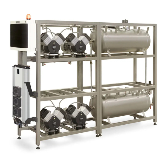
Page 10: Product Description
PRODUCT DESCRIPTION PRODUCT DESCRIPTION 7. VARIANTS The compressor is manufactured according to its intended application in the following variants: DK50 4x2VT/M Composed of modules: compressor module - 4x2V air pumps adsorption dryer air tank module – 2x110 l DK50 6x2VT/M... - Page 11 PRODUCT DESCRIPTION DK 50 6x2VT/M 06/2021 NP-DK50-Nx2VTM-AD-EN-3_06-2021...
-
Page 12: Accessories
Set of compressed air outlet filters The compressor may be equipped with a set of filters if specified. The filter set may be equipped with an air pressure regulator. The filter sets are identical for the DK50 4x2VT/M and DK50 6x2VT/M products. -
Page 13: Product Function
PRODUCT DESCRIPTION 9. PRODUCT FUNCTION 9.1. Compressor with adsorption dryer The compressor air pumps (1) draw in air through the inlet filter (8) and compress it through a non- return valve and into a manifold, from which it is routed to the adsorption dryer (3) through a connecting hose. - Page 14 PRODUCT DESCRIPTION Fig. 1: Compressor with adsorption dryer NP-DK50-Nx2VTM-AD-EN-3_06-2021 06/2021...
- Page 15 PRODUCT DESCRIPTION Fig. 2: Adsorption dryer 06/2021 NP-DK50-Nx2VTM-AD-EN-3_06-2021...
- Page 16 PRODUCT DESCRIPTION Fig. 3: Electrical box / switchboard The range of the pressure switch on the configured assemblies may only be adjusted after prior consultation with the manufacturer. Adjusting the pressure setting of the safety valve is expressly prohibited. The pressure relief valve automatically begins to vent air from the system if the pressure in the compressed air circuit exceeds its pre-set value.
-
Page 17: Technical Data
TECHNICAL DATA TECHNICAL DATA Compressors are designed for operation in dry, ventilated and dust-free indoor rooms under the following climactic conditions: +5°C to +40°C Temperature Relative humidity max. 70% Working pressure 6 – 8 bar DK50 6x2VT/M Nominal voltage V, Hz 3x400, 50 Frequency Capacity at 6 bar (FAD) - Page 18 TECHNICAL DATA Dependence of compressor output on working pressure NP-DK50-Nx2VTM-AD-EN-3_06-2021 06/2021...
- Page 19 TECHNICAL DATA Working pressure 6 – 8 bar DK50 4x2VT/M DK50 6x2VT/M Rated voltage V, Hz 3x400, 50 3x400, 50 Frequency Output at 6 bar (FAD) at l/min PDP-40°C 6.0 – 8.0 6.0 – 8.0 Working pressure Max. current 14.5...
- Page 20 TECHNICAL DATA Working pressure 8 – 10 bar DK50 6x2VT/M Rated voltage V, Hz 3x400, 50 Frequency Output at 6 bar (FAD) at l/min PDP-20°C 8.0 – 10.0 Working pressure Max. current Main circuit protection device rating Main electrical feeder Enclosure IP10 Motor output...
- Page 21 TECHNICAL DATA Working pressure 8 – 10 bar DK50 4x2VT/M DK50 6x2VT/M Rated voltage V, Hz 3x400, 50 3x400, 50 Frequency Output at 8 bar (FAD) at l/min PDP-40°C 8.0 – 10.0 8.0 – 10.0 Working pressure Max. current 15.5...
- Page 22 TECHNICAL DATA FAD correction of capacity for altitude Capacity given in the form of FAD („Free Air Delivery“) applies to the following conditions: 20°C Altitude 0 m.n.m. Temperature Atmospheric pressure 101325 Pa Relative humidity To calculate FAD compressor capacity in dependence on altitude, it is necessary to apply correction factor according to the following table: Altitude [m.n.m.] 0 -1500...
-
Page 23: Installation
INSTALLATION INSTALLATION Risk of incorrect installation. Only a qualified technician may install the compressor and place it into operation for the first time. Their duty is to train operating personnel on the use and maintenance of the equipment. An entry is made in the equipment installation record to certify installation and operator training. -
Page 24: Compressor Assembly
Space conditions Temperature +5°C ÷ +40°C Relative humidity 70% Recommended flow of cooling air: DK50 6x2VT/M - 1500m DK50 4x2VT/M – 1000m Applies for continuous operation and cooling air temperature of 20°C Cooling air inlet 11. COMPRESSOR ASSEMBLY 11.1. Handling and releasing the compressor ... - Page 25 INSTALLATION Fig. 5: Handling the compressor module Fig. 6: Levelling the compressor 06/2021 NP-DK50-Nx2VTM-AD-EN-3_06-2021...
- Page 26 Fig. 8: Releasing the air pumps Remove the transport stabilisers from the air pumps (X, Y, Z) (Fig. 8). DK50 4x2VT/M – 8x mounts. DK50 6x2VT/M – 12x mounts Assembly of the AD dryer ...
-
Page 27: Pneumatic Connection
INSTALLATION equipment with one hand on a handle and the other behind the dryer chamber when moving the equipment. Fig. 9: Handling the dryer High temperature hazard The placement of air flow impediments upstream or downstream of the cooler is prohibited. - Page 28 INSTALLATION Fig. 11: Pneumatic connection AD dryer compressed air inlet Connect the outlet (OUT) from the compressor’s manifold to the inlet (AIR IN) on the dryer (1). Use the 950 mm hose. Fig. 12: Compressed air inlet Burn or fire hazard! Caution! Hot surface! When installing the connecting hoses at the inlet to the air dryer, ensure that the temperature is not hazardous if it was to come into contact with an operator or other material.
- Page 29 INSTALLATION AD dryer compressed air outlet Connect the outlet (AIR OUT) from the dryer (1) to the compressor manifold. Use the 600 mm hose. Fig. 13: Compressed air outlet Condensate outlet from dryer Connect a hose to the outlet (1) from the automatic condensate drain (2) to drain piping or to the provided collection vessel.
-
Page 30: Electrical Connection
INSTALLATION 13. ELECTRICAL CONNECTION Unauthorised interference hazard Only a qualified electrician may install electrical components! Risk of damage to the device. The operator is obliged to provide circuit protection devices for the equipment per the specifications in valid technical standards. The product is delivered without a power cord. - Page 31 INSTALLATION Fig. 18: Connecting the power cord Connect the TN-S mains to the power supply terminal in the equipment’s junction box (F). Connect the electrical components to the mains in accordance with the valid electrical standards and regional regulations. Fig.
-
Page 32: Commissioning
INSTALLATION Fire hazard and risk of electric shock. Ensure the electrical cable does not touch hot parts of the device or connecting hoses. 14. COMMISSIONING Make sure all transport stabilizers were removed. Check that all compressed air hose connections are correct. ... -
Page 33: Pneumatc Diagrams
INSTALLATION 15. PNEUMATC DIAGRAMS DK50 4x2VT/M 06/2021 NP-DK50-Nx2VTM-AD-EN-3_06-2021... - Page 34 INSTALLATION DK50 6x2VT/M NP-DK50-Nx2VTM-AD-EN-3_06-2021 06/2021...
- Page 35 INSTALLATION Description to pneumatic diagrams: 1. Inlet filter 11. Pressure gauge 2. Air pump 12. Cooler 3. Compressor fan 13. Cooler fan 4. Solenoid valve 14. Air tank 5. Safety valve 15. Condensate drain valve 6. Non-return valve 16. Outlet valve 7.
-
Page 36: Operation
OPERATION OPERATION ONLY TRAINED PERSONNEL MAY OPERATE THE EQUIPMENT! Risk of electric shock. In case of emergency, disconnect the compressor from the mains (pull out the mains plug). Burn or fire hazard. When the compressor is running, the connecting hose between the compressor and dryer and parts of the dryer and aggregate may be hot enough to burn people or other material. -
Page 37: Switching The Compressor
OPERATION 16. SWITCHING THE COMPRESSOR After the pressure switch (6) is activated and circuit breakers FA13 (11) and FA14 (12) are turned to position I, the compressor air pumps sequentially come online (the air pumps in the second column or shelf react with a 2 s delay). Circuit breaker FA13 (11) functions as the main switch. The air pumps switch on (at ≤6 bar) and off (at ≥8 bar) automatically and are controlled by the LOGO! (13) controller and the pressure switch (6) based on compressed air usage. - Page 38 OPERATION A menu appears press▲ or ▼ to move the “>” cursor on the display to Set Clock.. and press OK to confirm A menu appears press ▲ or ▼ to select the day of the week press ►...
- Page 39 OPERATION this status is indicated by a flashing HA beacon and message on the display. The equipment has an intelligent alarm system that generates an alarm signal based on its priority (medium priority alarms have a higher priority than low priority alarms) Low priority alarm conditions The equipment is equipped to monitor and signal maintenance intervals.
-
Page 40: Switching Off The Compressor
OPERATION This message automatically disappears once the malfunction on the air pump is remedied and it is placed back into service. Alarm signals have priority over maintenance interval signals. As such, the light will indicate an alarm from any of the air pumps. One the alarm is over, the service interval is indicated by the activated HA beacon. -
Page 41: Product Maintenance
PRODUCT MAINTENANCE PRODUCT MAINTENANCE 18. PRODUCT MAINTENANCE The operator shall secure the completion of repeated testing of the equipment at least once every 24 months (EN 62353) or at the intervals defined by the applicable national regulations. A record of the test results must be made (e.g.: as per EN 62353, Annex G), along with the measurement methods. - Page 42 PRODUCT MAINTENANCE 18.1. Maintenance intervals operator qualified technician NP-DK50-Nx2VTM-AD-EN-3_06-2021 06/2021...
- Page 43 PRODUCT MAINTENANCE qualified technician 06/2021 NP-DK50-Nx2VTM-AD-EN-3_06-2021...
- Page 44 PRODUCT MAINTENANCE 18.2. Check of product operation Check air pump condition – the aggregates should be operating normally without excessive vibration or noise. Troubleshoot any problem or call in service personnel if trouble is detected. Visually inspect fan operation – the fans must be operating when the aggregates are running. Troubleshoot any problem or call in service personnel if trouble is detected.
- Page 45 PRODUCT MAINTENANCE 18.5. Condenste drain A wet floor resulting from overflow from the vessel poses a slip hazard. Condensate from compressors with air dryers is automatically drained into a vessel to collect condensate. Monitor the level in the vessel using the markings (depending on the volume of the vessel), and empty at least once a day.
- Page 46 PRODUCT MAINTENANCE Venting compressed air poses an injury hazard. Wear safety glasses when inspecting a safety valve. Turn the screw on the safety valve several rotations to the left until the safety valve releases air. Let the safety valve vent for only a few seconds.
- Page 47 PRODUCT MAINTENANCE 18.10. Check of solenoid valve operation Check their operation using the “Magnetic indicator” fixture as follows: Attach the fixture to the valve coil and if the motors are active at the valve coil, the indicator must rotate and if they are out of inactive, the indicator must not rotate.
- Page 48 PRODUCT MAINTENANCE Manual venting of pressure Turn off the compressor. Open the vent plugs on the outlet module on the equipment (Fig. 25). Fig. 25: Venting pressure from the dryer chambers Disconnect the hose (2) from the lower part of the condensate separator (3) (Fig. 26). Fig.
- Page 49 PRODUCT MAINTENANCE Turn off the compressor. Check the pressure in the dryer. If the dryer chambers are under pressure, proceed in accordance with Chapter 18.13. Unscrew the 8 screws (1). Disassemble the outlet panel (2) on which the filters (3) are mounted.
- Page 50 PRODUCT MAINTENANCE 18.16. Replacement of the logic valve ball Turn off the compressor. Check the pressure in the dryer. If the dryer chambers are under pressure, proceed in accordance with Chapter 18.13. Unscrew the 4 screws (1) and remove the cover (2).
- Page 51 PRODUCT MAINTENANCE 18.19. Replacement of solenoid valves Risk of electric shock. Shut off the compressed air source, turn off the equipment and disconnect it from the mains before working on the equipment. Working with pressurised pneumatic components poses a risk of injury. Disconnect the equipment from the mains and vent the pressure in the equipment and the pneumatic system to zero before working on the equipment.
- Page 52 PRODUCT MAINTENANCE Fig. 31: Solenoid valve replacement Solenoid valve assembly Replacement solenoid valves are delivered as disassembled replacement parts. The new valve must be assembled before a solenoid valve is replaced. Mount the valve coil (4-5) onto the valve body (4-4) and secure with the nut (4-6). ...
-
Page 53: Troubleshooting
TROUBLESHOOTING compressed air circuit exceeds its pre-set value. The pressure relief valve closes as the pressure drops. Working with pressurised pneumatic components poses a risk of injury. Prior to any work, disconnect the equipment from the mains, shut off the compressed air supply, and vent all pressure in the equipment to zero. - Page 54 TROUBLESHOOTING Damage to the safety valve could cause pressure to rise to hazardous levels. Never adjust a safety valve. Malfunction Possible cause Solution Problem with electrical power source Main breaker is off Check mains voltage Compressor does not Loose terminal in switchboard – tighten Power loss start Check the primary power connection -...
-
Page 55: Repair Service
TROUBLESHOOTING Replace damaged spring with new Failed (cracked) rubber mount spring spring Lack of ventilation in compressor room Secure suitable ambient conditions High ambient temperature causes Defective fans - replace compressors Cooling fans for aggregates, cooler and switch off in vertical enclosure do not work Defective temperature switch - replace stacks (overheating) -
Page 56: Long-Term Shutdown
TROUBLESHOOTING 20. LONG-TERM SHUTDOWN If the compressor will not be used for a prolonged time period, it is recommended to drain all condensate from the air tank and the condensate separator. Then turn on the compressor for 10 minutes, keeping the drain valve on the air tank open (7) (Fig. 1). Switch off the compressor using the main switch, close the condensate drain valve and disconnect the equipment from the mains. -
Page 57: Annex
ANNEX ANNEX 22. INSTALLATION RECORD 1. Product: (model) 2. Serial number: DK50 4X2VT/M DK50 6x2VT/M 3.1. User’s name: 3.2. Address of installation: 4. Equipment connected to the compressor: 5. Installation / Commissioning: 6. Contents of operator training: Product completeness check **... - Page 60 DK50 4x2VT/M DK50 6x2VT/M EKOM spol. s r.o., Priemyselná 5031/18, 921 01 PIEŠŤANY, Slovak Republic tel.: +421 33 7967255, fax: +421 33 7967223 e-mail: ekom@ekom.sk, www.ekom.sk NP-DK50-Nx2VTM-AD-EN-3_06-2021 112000481-0001...
Need help?
Do you have a question about the DK50 4x2VT/M and is the answer not in the manual?
Questions and answers