EKOM Event DK50 D Service Manual
Hide thumbs
Also See for Event DK50 D:
- User manual (94 pages) ,
- Installation, operation and mantenance manual (76 pages)
Table of Contents
Advertisement
Advertisement
Table of Contents

Related Manuals for EKOM Event DK50 D


Summary of Contents for EKOM Event DK50 D
- Page 1 PDF created with pdfFactory trial version www.pdffactory.com...
-
Page 2: Table Of Contents
SERVICE MANUAL 1. WARNINGS................................. 3 1.1. CE Marking ............................. 3 1.2. General warnings ............................ 3 1.3. General safety warnings......................... 3 1.4. Safety warnings regarding the protection against electric current ............. 3 1.5. Alert notices and symbols........................4 2. INFORMATION ON PRODUCT ........................... 5 2.1. -
Page 3: Warnings
SERVICE MANUAL 1. WARNINGS 1.1. CE Marking Products marked with CE mark of compliance meet safety guidelines of European Union (93/42/EEC). 1.2. General warnings • The installation, operation and maintenance manual is an integral part of the appliance. It is necessary to always keep this document close to the appliance. -
Page 4: Alert Notices And Symbols
SERVICE MANUAL • Prior the connecting the compressor, verify whether the mains voltage and frequency specified on the apparatus are in accordance with the local supply. • Prior to putting into operation, check for possible damages on the appliance and the air connectors. -
Page 5: Information On Product
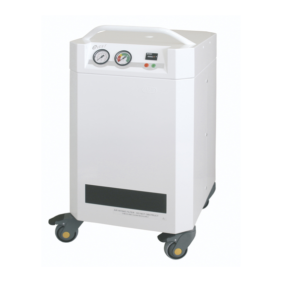
SERVICE MANUAL 2. INFORMATION ON PRODUCT 2.1. Usage on purpose • This medical compressor, hereinafter referred to as the compressor, is the source of clean, oil- free pressurized air for use with respiratory equipment. Due to the silent operation of the compressor, it is possible to place the unit near the respiratory appliance beside the bed of the patient. -
Page 6: Technical Data
SERVICE MANUAL 3. TECHNICAL DATA TYPE DK50 D DK50 DM Output flow at pressure 3,5 bar Lit.min max. 40 max. 60 Rated voltage / Frequency V/Hz 230/50 230/60* 115/60* 230/50 230/60* 115/60* Nominal current µm Filtration of air to Pressure dew point at max. 5°C under 5°C under output flow and at an air... -
Page 7: Storage And Transport Conditions
SERVICE MANUAL 4. STORAGE AND TRANSPORT CONDITIONS The compressor is dispatched from the factory in transport packing with the pump fixed. Thus the appliance is protected from damage during transport. During transport, if it is possible, always use the original packaging of the compressor. -
Page 8: Unfixing Of The Air Pump
SERVICE MANUAL 5.2. Unfixing of the air pump After unpacking, place the compressor upright with the castor wheels firmly on the ground (see annex). • Remove the front and back cover unscrewing screws 6 pcs on the side of cabinet. •... -
Page 9: First Putting Into Operation
SERVICE MANUAL 5.5. First putting into operation • Check whether all fixing screws used during transport were removed. • Check that the connections of the compressed air supplies are correct. • Check for proper connection to the mains supply. • Switch on the pressure switch (6) to position “I”. After first putting the compressor into operation, the air chamber of compressor is pressurized to a ‘switching-off’... -
Page 10: Cleaning And Replacement Of Air Intake Filter
SERVICE MANUAL pointer of indicator will move from the green zone and the air from compressor will not reach the declarable parameters (see technical data). The hour meter (5) indicates total running time of the air pump. 6.3. Cleaning and replacement of air intake filter There is air intake filter (12) at the front side. -
Page 11: Service Kits
SERVICE MANUAL 7.2. Service kits type 4EA-026 Part No. 604041026 2000 hrs Prefilter (A) Input filter (B) Filter (C) Filter (D) Type 4KB-565 4KA-292 40 µm 5 µm Number 025000012 025000005 025200070 025200071 type 4EA - 027 Part No. 604041027 4000 hrs Inlet filter Piston with rod... -
Page 12: Preparations For Service
SERVICE MANUAL 7.3. Preparations for service For executing service activities, the manufacturer recommends to use the following preparations that may be ordered separately: • Cylinder fitting Part No.023000239 • Tools for stripping the bearing Part No.191000001 • Pressure gauge set Part No.191000007 •... -
Page 13: Replacement Of Filter In The Pressure Regulator
SERVICE MANUAL 7.7. Replacement of filter in the pressure regulator Prior the intervention to the appliance it is necessary to decrease the pressure of air in air chamber to zero and to disconnect the appliance from mains. • Unscrew the cover of filter and pull it out. •... -
Page 14: Verification Of Tightness Of Joints And Check Inspection Of Appliance
SERVICE MANUAL 7.10. Verification of tightness of joints and check inspection of appliance Test of leakage: • By disconnecting output hose from fast-on coupling marked OUT (10) the consumption of compressed air is stopped. • Pressurize pressure tank (forced startup of compressor can be done for example by releasing of part of air via supplied device). -
Page 15: Replacement Of Piston With Connecting Rod And Piston Rings
SERVICE MANUAL 7.13. Replacement of piston with connecting rod and piston rings • Is necessary to disconnect pressure hose (1). • Disassemble crank case cap (2), complete cylinder head (3), spring (4), seat of membrane (5) with O-ring (6) (2 pcs) and carefully take out cylinder (7). -
Page 16: Fault Finding And Troubleshooting
SERVICE MANUAL 10. FAULT FINDING AND TROUBLESHOOTING Prior to repairing the appliance it is necessary to reduce the pressure of the air in the air chamber to zero and disconnect the appliance from the mains supply. Trained service personnel can only perform the activities connected to the troubleshooting guide. FAILURE POSSIBLE CAUSE TROUBLESHOOTING... -
Page 17: Information On Repair Service
SERVICE MANUAL 11. INFORMATION ON REPAIR SERVICE The guarantee and extended guarantee repairs are to be completed by the manufacturer, or an organization authorized by the manufacturer. The manufacturer reserves the right to modify the appliance in a way that will not impact substantially on the operation of the appliance. -
Page 18: Wiring Diagram
SERVICE MANUAL 13. WIRING DIAGRAM 230V / 50Hz 00000 230V / 60Hz DK50 D 115V / 60Hz TYPE B 40°C 80°C 230V / 50Hz DK50 DM 00000 230V / 60Hz 115V / 60Hz TYPE B 40°C 80°C Legend: 1. Main input, power switch, primary fuses 8. -
Page 19: Pneumatic Diagram
SERVICE MANUAL 14. PNEUMATIC DIAGRAM CONTROL PANEL WALL Legend: 1. Intake filter 11. Air Outlet 2. Input filter 12. Air Inlet 3. Compressor 13. Main input, power switch, primary fuses 4. Solenoid valve 14. Pressure switch 5. Sound absorber 15. Humidity indicator 6. - Page 20 SERVICE MANUAL - 20 - SM-eVENT-GB-3_8-2006.doc PDF created with pdfFactory trial version www.pdffactory.com...
- Page 21 SERVICE MANUAL SM-eVENT-GB-3_8-2006.doc PDF created with pdfFactory trial version www.pdffactory.com...
- Page 22 SERVICE MANUAL - 22 - SM-eVENT-GB-3_8-2006.doc PDF created with pdfFactory trial version www.pdffactory.com...
- Page 23 SERVICE MANUAL SM-eVENT-GB-3_8-2006.doc PDF created with pdfFactory trial version www.pdffactory.com...
-
Page 24: List Of Spare Parts
SERVICE MANUAL 15. LIST OF SPARE PARTS 1. L screwing 8/6-1/4 025500122 40. Manometer complete 4BA-271 604011271 2. Reduction 3/8F-1/4F 025500123 41. Humidity indicator compl. 4BA-272 604011272 3. Plug 1/8 M 025400029 42. Operation hours counter 4. Check valve 3/8M-3/8M 025300007 HK30.G0 230V/50Hz 037200008... -
Page 25: Sm-Event-Gb-3_8-2006.Doc
SERVICE MANUAL 77. Frame 83. Foam 3BA-292 for DK50D 603011292 4KB-529 for DK50D 061000167 3BA-325 for DK50DM 603011325 4KB-596 for DK50DM 061000178 78. Front door 84. Foam 3KB-551 for DK50D 023000324 4KB-528 for DK50D 061000166 3KB-593 for DK50DM 023000356 4KB-595 for DK50DM 061000177 79. - Page 26 SERVICE MANUAL - 26 - SM-eVENT-GB-3_8-2006.doc PDF created with pdfFactory trial version www.pdffactory.com...
- Page 27 SERVICE MANUAL EKOM spol. s r.o. Priemyselná 5031 / 18 9 2 1 0 1 P I E Š Ť A N Y Slovak republic tel.: +421 33 7967255 fax: +421 33 7967223 e-mail: ekom@ekom.sk www.ekom.sk SM-eVENT-GB-3_8-2006.doc PDF created with pdfFactory trial version...
- Page 28 CHANGE 1 Description • Castors φ 50mm with connecting thread M8 are changed by castors φ 75mm with connecting thread M10. Validity • Type eVENT DK50 D from serial number A0941-9-05 • Type eVENT DK50 DM from serial number B0479-9-05 Range •...
- Page 29 SERVICE MANUAL CHANGE 3 Description • Solenoid valve AVS-Römer EGV 211-B97 is changed by valve Danfoss EV 220A 10B G3/8 Validity • Type eVENT DK50 D from serial number A1245-2-06 • Type eVENT DK50 DM from serial number B0690-2-06 Range •...
Need help?
Do you have a question about the Event DK50 D and is the answer not in the manual?
Questions and answers