EKOM DK50 4x4VRT/M User Manual
Hide thumbs
Also See for DK50 4x4VRT/M:
- User manual (47 pages) ,
- User manual (72 pages) ,
- User manual (58 pages)
Table of Contents
Advertisement
Quick Links
Advertisement
Table of Contents

Related Manuals for EKOM DK50 4x4VRT/M


Summary of Contents for EKOM DK50 4x4VRT/M
- Page 1 DK50 4x4VRT/M DK50 6x4VRT/M User manual...
- Page 3 DK50 4x4VRT/M COMPRESSOR DK50 6x4VRT/M EKOM spol. s r. o. Priemyselná 5031/18 SK-921 01 Piešťany Slovak Republic tel.: +421 33 7967255 fax: +421 33 7967223 www.ekom.sk email: ekom@ekom.sk DATE OF LAST REVISION 03/2021 NP-DK50-Nx4VRTM-AD-A- EN-4_03-2021 112000555-0001...
- Page 4 CONTENTS ....................5...
-
Page 5: Table Of Contents
CONTENTS CONTENTS GENERAL INFORMATION ......................6 CONFORMITY WITH THE REQUIREMENTS OF THE EUROPEAN UNION ....6 SYMBOLS ........................6 DEVICE USE ........................7 GENERAL SAFETY INSTRUCTIONS ................8 STORAGE AND TRANSPORT CONDITIONS ..............9 PRODUCT DESCRIPTION ......................10 VARIANTS ........................10 ACCESSORIES ...................... -
Page 6: General Information
GENERAL INFORMATION GENERAL INFORMATION Carefully read this user manual before using the product and carefully store it for future reference. The user manual aids in the proper use, including installation, operation and maintenance, of the product. The user manual corresponds to the configuration of the product and its compliance with applicable safety and technical standards at the time of its printing. -
Page 7: Device Use
GENERAL INFORMATION Fuse Compressed air inlet Compressed air outlet Control wire input Package handling label – fragile Package handling label – this side up Package handling label – keep dry Package handling label – temperature limits Package handling label – limited stacking Package label –... -
Page 8: General Safety Instructions
GENERAL INFORMATION Any other use of the product beyond the intended use is considered as incorrect use. The manufacturer is not responsible for any damages or injuries as a result of incorrect use or disobedience to instructions stated in this User manual. All risks shall be solely borne by the user/operator. -
Page 9: Storage And Transport Conditions
GENERAL INFORMATION 5. STORAGE AND TRANSPORT CONDITIONS The compressor is shipped from the manufacturer in transport packaging. This protects the product from damage during transport. Potential for damage to pneumatic components. The compressor must be transported only when all air has been vented. Before moving or transporting the compressor, release all the air pressure from the tank and pressure hoses, from dryer chambers and drain condensate from the tank and from the condensate separator on the dryer. -
Page 10: Product Description
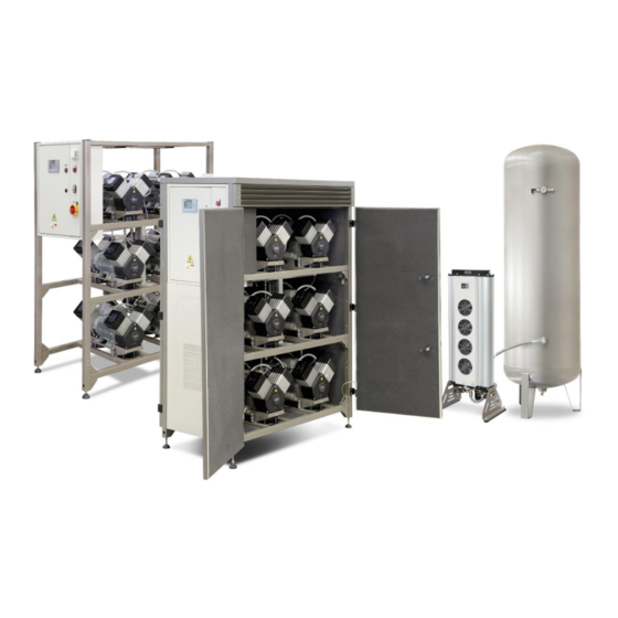
PRODUCT DESCRIPTION PRODUCT DESCRIPTION 6. VARIANTS The compressor is manufactured according to its intended application in the following variants: DK50 4x4VRT/M Composed of modules: compressor module with 4 or 6 aggregates and controls for the DK50 6x4VRT/M assembled unit adsorption dryer with connecting hoses... - Page 11 PRODUCT DESCRIPTION DK 50 6x4VRT/M DK50 4x4VRTS/M 03/2021 NP-DK50-Nx4VRTM-AD-A-EN-4_03-2021...
-
Page 12: Accessories
7. ACCESSORIES Accessories that are not included in the standard order must be ordered separately. DK50 4x4VRT/M performance upgrade kit If DK50 4x4VRT compressor performance is not keeping up with demand, a simple solution is to contact the manufacturer about the DK50 6x4VRT/M performance upgrade kit. - Page 13 PRODUCT DESCRIPTION Article number DK50 4x4VRT/M 447000001-021 DK50 4x4VRTS/M 447000001-020 DK50 6x4VRT/M 447000001-019 DK50 6x4VRTS/M 447000001-018 Set of compressed air outlet filters The compressor may be equipped with a set of filters if specified. The filter set may be equipped with an air pressure regulator.
-
Page 14: Product Function
Enclosing the compressor module reduces the noise generated by the compressor by up to 11 dB(a) compared to the compressor module without the enclosure while ensuring sufficient cooling for the aggregates themselves for S1 class continuous operation. With central intake Article number DK50 4x4VRT/M 447000001-022 DK50 6x4VRT/M DK50 4x4VRT/M 447000001-023 DK50 6x4VRT/M 8. - Page 15 PRODUCT DESCRIPTION Fig. 1 - Compressor with dryer 03/2021 NP-DK50-Nx4VRTM-AD-A-EN-4_03-2021...
- Page 16 PRODUCT DESCRIPTION Fig. 2 – Electrical box / switchboard Descriptions for figures 1-2: Compressor module 13. Connecting hoses Air tank 14. Electrical cables Electrical box / switchboard 15. Drain valve Safety valve 16. Display Pressure sensor 17. Indicator - alarm Pressure gauge 18.
-
Page 17: Technical Data
TECHNICAL DATA TECHNICAL DATA Compressors are designed for operation in dry, ventilated and dust-free indoor rooms under the following climactic conditions: +5°C to +40°C Temperature Relative humidity max. 70% DK50 DK50 DK50 DK50 Working pressure 6 – 8 bar 4x4VRT/M 4x4VRTS/M 6x4VRT/M 6x4VRTS/M... - Page 18 TECHNICAL DATA Specify the compressor version when ordering Consult any other range of pressure with the supplier Weight is indicative and only applies to the product without accessories Applies to ambient temperatures of <30°C PDP – pressure dew point Dependence of compressor output on working pressure NP-DK50-Nx4VRTM-AD-A-EN-4_03-2021 03/2021...
- Page 19 TECHNICAL DATA DK50 DK50 DK50 DK50 Working pressure 8 – 10 bar 4x4VRT/M 4x4VRTS/M 6x4VRT/M 6x4VRTS/M Rated voltage V, Hz 3x400, 50 3x400, 50 3x400, 50 3x400, 50 Frequency Output at 8 bar (FAD) at l/min. 1040 1040 PDP-20°C Output at 8 bar (FAD) at l/min.
- Page 20 TECHNICAL DATA Dependence of compressor output on working pressure FAD correction of capacity for altitude Capacity given in the form of FAD („Free Air Delivery“) applies to the following conditions: 20°C Altitude 0 m.n.m. Temperature Atmospheric pressure 101325 Pa Relative humidity To calculate FAD compressor capacity in dependence on altitude, it is necessary to apply correction factor according to the following table: Altitude [m.n.m.]...
-
Page 21: Installation
INSTALLATION INSTALLATION Risk of incorrect installation. Only a qualified technician may install the compressor and place it into operation for the first time. Their duty is to train operating personnel on the use and maintenance of the equipment. An entry is made in the equipment installation record to certify installation and operator training. -
Page 22: Compressor Assembly
Space conditions Temperature +5°C ÷ +40°C Relative humidity 70% Recommended flow of cooling air: DK50 6x4VRT/M - 3000 m DK50 4x4VRT/M – 2250 m Applies for continuous operation and cooling air temperature of20°C Cooling air inlet 10. COMPRESSOR ASSEMBLY 10.1. Handling and releasing the compressor ... - Page 23 Fig. 6: Releasing the air pumps Remove the transport stabilisers from the air pumps (Fig. 6). DK50 4x4VRT/M – 8 mounts. DK50 6x4VRT/M – 12 mounts 03/2021 NP-DK50-Nx4VRTM-AD-A-EN-4_03-2021...
- Page 24 INSTALLATION Air tank assembly Fig. 7:Handling the air tank Position the air tank at the site of installation and anchor it to the floor. (Fig. 7) Assembly of the AD dryer Remove the dryer from the packaging. Install the dryer in its operating position (Fig.
-
Page 25: Pneumatic Connection
INSTALLATION Fig. 8: Handling the dryer 11. PNEUMATIC CONNECTION Connect compressor module, dryer module, and the air tank with the provided hoses. (Fig. 9) Fig. 9: Connecting the compressor module, dryer and air tank 03/2021 NP-DK50-Nx4VRTM-AD-A-EN-4_03-2021... - Page 26 INSTALLATION Fig. 10: Connecting the enclosed compressor module, dryer and air tank hose length 1 [mm] hose length 2 [mm] DK50 4x4VRT/M 1000 DK50 4x4VRTS/M DK50 6x4VRT/M 1300 1000 DK50 6x4VRTS/M 1000 AD dryer compressed air inlet Connect to the compressor outlet (Fig.
- Page 27 INSTALLATION Burn or fire hazard! Caution! Hot surface! When installing the connecting hoses at the inlet to the air dryer, ensure that the temperature is not hazardous if it was to come into contact with an operator or other material. AD dryer compressed air outlet ...
-
Page 28: Electrical Connection
INSTALLATION Fig. 14: Air outlet from the air tank Potential for damage to pneumatic components. Ensure the air hoses are not kinked. 12. ELECTRICAL CONNECTION Unauthorised interference hazard Only a qualified electrician may install electrical components! Risk of damage to the device. The operator is obliged to provide circuit protection devices for the equipment per the specifications in valid technical standards. - Page 29 INSTALLATION Fig. 15: Connecting the compressor to the dryer Fig. 16: Connecting the control signal 1. Harting connector Proper routing of the electrical cable to the dryer 03/2021 NP-DK50-Nx4VRTM-AD-A-EN-4_03-2021...
- Page 30 INSTALLATION Fire hazard and risk of electric shock. Ensure the electrical cable does not touch hot parts of the device or connecting hoses. Fig. 17: Connecting the compressor to the pressure sensor Cable bridge NP-DK50-Nx4VRTM-AD-A-EN-4_03-2021 03/2021...
- Page 31 INSTALLATION Fig. 18: Electrical cord Fig. 19: Connecting the power cord Description of air pump controls The air pumps are controlled in trios based on real demand. One trio is always set as the MASTER (e.g. M1-3) and the others as SLAVE (e.g. M4-6). The set of three Slave air pumps operate under the following conditions (see Fig.
- Page 32 INSTALLATION Fig. 20: Air pump controls – motors M1-M3 – motors M4-M6 UL – upper limit – bottoms limit → Master = 6.2, SLAVE = 6.0 Description of adsorption dryer solenoid valve control The inlet valves (Inlet A and B) switch every 120 seconds. The regeneration valves open variably based on the real load, e.g.
- Page 33 INSTALLATION Ethernet connection The compressor may be connected to an Ethernet 10/100 M network via the controller as follows: Use the RJ-45 connector on the switchboard door to connect a cable to the Ethernet network. The user shall then request IT staff to connect the compressor to the customer’s Ethernet network.
-
Page 34: Commissioning
INSTALLATION Monitoring memory variables The “LOGO! Variable” function is the other option for monitoring compressor parameters using selected memory variables. Click the “LOGO! Variable” button on the display to bring up a screen and then use the “Add Variable” button to select specific memory variables for monitoring based on the mapping provided by the compressor manufacturer. -
Page 35: Pneumatic Diagrams
INSTALLATION 14. PNEUMATIC DIAGRAMS DK50 4x4VRT/M, DK50 4x4VRTS/M 03/2021 NP-DK50-Nx4VRTM-AD-A-EN-4_03-2021... - Page 36 INSTALLATION DK50 6x4VRT/M, DK50 6x4VRTS/M NP-DK50-Nx4VRTM-AD-A-EN-4_03-2021 03/2021...
- Page 37 INSTALLATION Description to pneumatic diagrams: 1. Inlet filter 14. Air tank 2. Air pump 15. Drain valve 3. Compressor fan 16. Outlet valve 4. Solenoid valve 17. Dryer solenoid valve 5. Safety valve 18. Central fan 6. Non-return valve 19. Condensate collection vessel 7.
-
Page 38: Operation
OPERATION OPERATION ONLY TRAINED PERSONNEL MAY OPERATE THE EQUIPMENT! Risk of electric shock. In case of emergency, disconnect the compressor from the mains (pull out the mains plug). Burn or fire hazard. When the compressor is running, the connecting hose between the compressor and dryer and parts of the dryer and aggregate may be hot enough to burn people or other material. -
Page 39: Switching On The Compressor
OPERATION 15. SWITCHING ON THE COMPRESSOR Turn the main switch (19) into the “I” position on the compressor switchboard. The white indicator P1 (17) lights up and the display (16) on the switchboard door shows the following message: RUN HOURS: operating hours PRESSURE: current pressure TEMP_IN: internal temperature (only for enclosed version) - Page 40 OPERATION Motors are on RUN MODE – all aggregates are switched RUN HOURS: operating hours TIME-TO-GO MN - time to the next maintenance / service work (in hours). Motors are switched off PRESSURE: current working pressure STANDBY MODE – all aggregates are switched off RUN HOURS: operating hours TIME-TO-GO MN - time to the next...
- Page 41 OPERATION F1 - in alarm display mode, press to switch back to normal operating mode for 60 seconds. Backlit screen. F2 – information on operating hours and maintenance intervals. F3 – scrolls through: Motor malfunctions Number of motor starts Maximum temperatures 03/2021 NP-DK50-Nx4VRTM-AD-A-EN-4_03-2021...
- Page 42 OPERATION F4 - SERVICE TECHNICIAN BUTTON (after completing service or maintenance work - hold for 5 seconds to reset the 2,000 hour maintenance interval.) Note: Pressing F1-3 on the control panel turns on the display back light for 30 seconds. Equipment operation Normal operating mode is shown when the equipment is operating and the functional and control buttons are used to browse through the following:...
- Page 43 OPERATION Pressing F4: F4 is only active if the maintenance screen appears once 2000 hours of operation have been passed (see the maintenance alarm). Press and hold F4 for at least 5 seconds to set a new interval. The screen switches back to normal operating mode once the new interval is set.
- Page 44 OPERATION Alarms The equipment has an intelligent monitoring system that generates an alarm signal based on priority (medium priority alarms have higher priority than low priority alarms). Alarm signals have a higher priority than maintenance/service interval signals. The maintenance/service interval is measured from the first time the equipment is energised. All alarms are accompanied by a blinking red P2 (Alarm) indicator.
- Page 45 OPERATION drops below the limit. The compressor supplies air to the compressed air system as needed and without restriction. Compressor module internal temperature exceeds the limit. WARNING - high temperature alarm inside an enclosed compressor. The display flashes orange. This alarm appears if the temperature inside the enclosed compressor module exceeds the 70°C limit for at least 30...
- Page 46 OPERATION Low pressure alarm at elevated compressed air demand. SIGNALING – low pressure alarm at elevated compressed air demand. The display flashes orange. PRESSURE - current pressure in the system The display automatically disappears once the air pressure is above 3 bar. compressor supplies compressed air system as needed and...
-
Page 47: Switching Off The Compressor
OPERATION 16. SWITCHING OFF THE COMPRESSOR Use the main switch, Q10, to switch off the compressor for maintenance or other reasons; the switch also functions as a central stop button. The compressor is disconnected from the mains with the exception of the mains terminal block X0. Vent the air tank by disconnecting from the central compressed air circuit and opening the outlet valve (Fig. -
Page 48: Product Maintenance
PRODUCT MAINTENANCE PRODUCT MAINTENANCE 17. PRODUCT MAINTENANCE The operator shall secure the completion of repeated testing of the equipment at least once every 24 months (EN 62353) or at the intervals defined by the applicable national regulations. A record of the test results must be made (e.g.: as per EN 62353, Annex G), along with the measurement methods. - Page 49 PRODUCT MAINTENANCE The work below may only be performed by trained personnel as follows: Before beginning any of the following maintenance work, first switch the main switch on the side of the switchboard to the “0” position. Please follow the recommended service intervals for the equipment to ensure proper and safe operation.
- Page 50 PRODUCT MAINTENANCE 17.1. Maintenance intervals operator qualified technician NP-DK50-Nx4VRTM-AD-A-EN-4_03-2021 03/2021...
- Page 51 PRODUCT MAINTENANCE qualified technician 03/2021 NP-DK50-Nx4VRTM-AD-A-EN-4_03-2021...
- Page 52 PRODUCT MAINTENANCE qualified technician NP-DK50-Nx4VRTM-AD-A-EN-4_03-2021 03/2021...
- Page 53 PRODUCT MAINTENANCE 17.2. Check of product operation Check aggregate condition – the aggregates should be operating normally without excessive vibration or noise. Troubleshoot any problem or call in service personnel if trouble is detected. Visually inspect fan operation – the fans must be operating when the aggregates are running. Troubleshoot any problem or call in service personnel if trouble is detected.
- Page 54 PRODUCT MAINTENANCE Inspect the connector X50 (dryer and cooler) and the pressure sensor (B1) (in the pressure vessel). 17.5. Condensate drain A wet floor resulting from overflow from the vessel poses a slip hazard. Condensate from compressors with air dryers is automatically drained into a vessel to collect condensate.
- Page 55 PRODUCT MAINTENANCE 17.7. Check of safety valve Damage to the safety valve could cause pressure to rise to hazardous levels. Never use the safety valve to release the air pressure in the air tank. This could damage the safety valve. The valve is set to the maximum permitted pressure by the manufacturer.
- Page 56 PRODUCT MAINTENANCE filter cover (7). (Fig. 27) Remove the 2 nuts (8) on the filter bracket (9) and remove the filter (10). At Point B (on the sides (11), remove the 2 nuts (12), washers (13), release the filter bracket (14) and remove the filter (15).
- Page 57 PRODUCT MAINTENANCE Air tank: Check for proper operation of the non-return valve on the air tank by disconnecting the pressure hose from the valve. Check the check valve operation once the air tank has come up to pressure and with the compressor off. No compressed air may leak. 17.11.
- Page 58 PRODUCT MAINTENANCE Use of aggressive detergents and disinfectants containing alcohol and chlorides can lead to surface damage and discolouration. AD dryer maintenance 17.15. Venting pressure from the dryer The equipment is designed to permit the safe venting of pressure within 10 seconds after the compressor is shut off.
- Page 59 PRODUCT MAINTENANCE Fig. 31: Venting pressure from the cooler and condensate separator The process of manually venting pressure from the equipment is complete after approximately 2 minutes. 17.16. Replacement of the dryer’s internal filters Working with pressurised pneumatic components poses a risk of injury. Prior to any work, disconnect the equipment from the mains, shut off the compressor and vent all pressure in the equipment to zero.
- Page 60 PRODUCT MAINTENANCE Turn off the compressor. Check the pressure in the dryer. If the dryer chambers are under pressure, proceed in accordance with Chapter 17.15. Unscrew the 8 screws (1). Remove the outlet panel (2). ...
- Page 61 PRODUCT MAINTENANCE Unscrew the silencer (1). Install a new silencer. Fig. 35: Replacement of the silencer 17.20. Inspecting the cooler and fan The equipment, in particular the compressor fan, cooler fan, and the cooler, must be kept clean to ensure efficient drying.
- Page 62 PRODUCT MAINTENANCE on the threads of the screws (such as Loctite 243). Reattach the solenoid valve connector and attach with a screw (1). Switch on the compressor. Check for any dryer leaks. Fig. 36: Solenoid valve replacement Solenoid valve assembly Replacement solenoid valves are delivered as disassembled replacement parts.
- Page 63 PRODUCT MAINTENANCE Fig. 37: Solenoid valve assembly 17.22. Pressure relief valve The pressure relief valve automatically begins to vent air from the system if the pressure in the compressed air circuit exceeds its pre-set value. The pressure relief valve closes as the pressure drops.
-
Page 64: Long-Term Shutdown
PRODUCT MAINTENANCE Fig. 38: Pressure relief valve 18. LONG-TERM SHUTDOWN If the compressor will not be used for a prolonged time period, it is recommended to drain all condensate from the air tank and the condensate separator. Then turn on the compressor for 10 minutes, keeping the drain valve on the air tank open (15) (Fig. -
Page 65: Troubleshooting
TROUBLESHOOTING TROUBLESHOOTING Risk of electric shock. Before interfering with the equipment, first disconnect it from the mains (remove the power socket). Working with pressurised pneumatic components poses a risk of injury. Before interfering with the equipment, vent the air tank and the compressed air system to zero pressure. - Page 66 TROUBLESHOOTING system – seal loose joints often, even without system demand for air Test check vales and clean, or replace Leaky check valves if damaged Leak through solenoid valves once Clean the check valve - replace if regeneration is complete damaged Leak at pressure sensor and safety Test their function and clean, or replace...
-
Page 67: Repair Service
TROUBLESHOOTING air tank, then dry the air tank, and the dryer must be regenerated, best when using continuous compressor operation at a pressure of around 7.0 bar for a period of at least 1 hour. Check the moisture content of the air exiting the air tank (see the Technical data chapter) to prevent damage to connected downstream equipment. -
Page 68: Annex
ANNEX ANNEX 21. MAPPING PARAMETERS NP-DK50-Nx4VRTM-AD-A-EN-4_03-2021 03/2021... - Page 69 ANNEX 03/2021 NP-DK50-Nx4VRTM-AD-A-EN-4_03-2021...
-
Page 70: Installation Record
ANNEX 22. INSTALLATION RECORD 1. Product: (model) 2. Serial number: DK50 4X4VRT/M DK50 4x4VRTS/M DK50 6x4VRT/M DK50 6x4VRTS/M 3.1. User’s name: 3.2. Address of installation: 4. Equipment connected to the compressor: 5. Installation / Commissioning: 6. Contents of operator training:... - Page 74 DK50 4x4VRT/M DK50 6x4VRT/M EKOM spol. s r.o., Priemyselná 5031/18, 921 01 PIEŠŤANY, Slovak Republic tel.: +421 33 7967255, fax: +421 33 7967223 e-mail: ekom@ekom.sk, www.ekom.sk NP-DK50-Nx4VRTM-AD-A-EN-4_03-2021 112000555-0001...
Need help?
Do you have a question about the DK50 4x4VRT/M and is the answer not in the manual?
Questions and answers