EKOM DK50-10 User Manual
Hide thumbs
Also See for DK50-10:
- User manual (276 pages) ,
- Installation, operation and maintenance manual (136 pages) ,
- Service manual (20 pages)
Table of Contents
Advertisement
Available languages
Available languages
Quick Links
Advertisement
Chapters
Table of Contents

Related Manuals for EKOM DK50-10


Summary of Contents for EKOM DK50-10
- Page 1 DK50-10 User manual Benutzerhandbuch Návod na použitie...
- Page 3 COMPRESSOR KOMPRESSOR DK50-10 KOMPRESOR EKOM spol. s r. o. Priemyselná 5031/18 SK-921 01 Piešťany Slovak Republic tel.: +421 33 7967255 fax: +421 33 7967223 www.ekom.sk email: ekom@ekom.sk DATE OF LAST REVISION DATUM DER LETZTEN ÜBERARBEITUNG 10/2019 DÁTUM POSLEDNEJ REVÍZIE NP-DK50-10-A-4_10-2019-...
- Page 4 CONTENTS ....................5 INHALT ......................41 OBSAH ......................77...
-
Page 5: Table Of Contents
SWTICHNING ON THE COMPRESSOR ............... 29 SWITCHING OFF THE COMPRESSOR ................ 29 PRODUCT MAINTENANCE ......................30 PRODUCT MAINTENANCE ................... 30 LONG-TERM SHUTDOWN .................... 38 DISPOSAL OF DEVICE ....................38 TROUBLESHOOTING ........................39 REPAIR SERVICE ......................40 ANNEX ............................113 INSTALLATION RECORD ................... 113 10/2019 NP-DK50-10-A-4_10-2019-MD... -
Page 6: General Information
The following symbols and marks are used in the User manual, on the device and its packaging: General warning Warning – risk of electric shock Warning - compressor is controlled automatically Warning – hot surface General caution Read the operating instructions Refer to instruction manual CE – marking Serial number Protecting earthing Fuse NP-DK50-10-A-4_10-2019-MD 10/2019... -
Page 7: Device Use
Any other use of the product beyond the intended use is considered as incorrect use. The manufacturer is not responsible for any damages or injuries as a result of incorrect use or disobedience to instructions stated in this User manual. All risks shall be solely borne by the user/operator. 10/2019 NP-DK50-10-A-4_10-2019-MD... -
Page 8: General Safety Instructions
The guarantee does not apply to damages arising from use of accessories and spare parts other than prescribed or recommended by the manufacturer and the manufacture is not responsible for them. NP-DK50-10-A-4_10-2019-MD 10/2019... -
Page 9: Storage And Transport Conditions
Products can be stored in rooms and means of transport that are free from any traces of volatile chemical substances under the following climatic conditions: from –25°C o +55°C, in 24h to +70°C Temperature max. 90% (without condensation/ non- Relative humidity condensing) 10/2019 NP-DK50-10-A-4_10-2019-MD... -
Page 10: Product Desription
REG10 DK50-10Z, DK50-10Z/M 447000001-042 Filters set Compressor can be equipped with a filters set of outlet compressed air as required. Filters set may include pressure regulator. The sets of filters are suitable accessories for the compressors specified above. NP-DK50-10-A-4_10-2019-MD 10/2019... -
Page 11: Product Function
This is why there is a gradual, slow drop in pressure even when there is no demand for compressed air (from the air tank), however, this is not a malfunction The pressure tank is dry and does not need to be drained. 10/2019 NP-DK50-10-A-4_10-2019-MD... - Page 12 14 Dryer cooler 15 Filter 16 Solenoid valve of condensate drain 17 Compressed air outlet 18 Circuit breaker switch 19 Condensate collection vessel 20 Magnetic holder 21 Fan 22 Switch 23 Hours counter 24 Socket 25 Cabinet fan NP-DK50-10-A-4_10-2019-MD 10/2019...
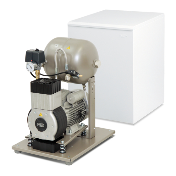
- Page 13 PRODUCT DESRIPTION Fig. 2: DK50-10Z/M – Compressor with dryer 10/2019 NP-DK50-10-A-4_10-2019-MD...
- Page 14 PRODUCT DESRIPTION Fig. 3: Compressor DK50-10S/M (8-10bar) NP-DK50-10-A-4_10-2019-MD 10/2019...
-
Page 15: Technical Data
State the compressor variant in the order For other range of pressure consult with the supplier Weight value is only informative data and applies only to a product without any accessories Dependence of compressor capacity on working pressure 10/2019 NP-DK50-10-A-4_10-2019-MD... - Page 16 State the compressor variant in the order For other range of pressure consult with the supplier Weight value is only informative data and applies only to a product without any accessories Dependence of compressor capacity on working pressure NP-DK50-10-A-4_10-2019-MD 10/2019...
- Page 17 State the compressor variant in the order For other range of pressure consult with the supplier Weight value is only informative data and applies only to a product without any accessories Dependence of compressor capacity on working pressure 10/2019 NP-DK50-10-A-4_10-2019-MD...
- Page 18 To calculate FAD compressor capacity in dependence on altitude, it is necessary to apply correction factor according to the following table: Altitude [m.n.m.] 0 -1500 1501 - 2500 2501 - 3500 3501 - 4500 FAD correction factor 0,71 0,60 NP-DK50-10-A-4_10-2019-MD 10/2019...
-
Page 19: Installation
Use the compressor base for gripping, when manipulating with the compressor. Do not use any other compressor parts (pump, cooler, etc.) for gripping the compressor. Fig. 4: Manipulation with the compressor Remove transport fixing elements from the pumps (Fig. 5). 10/2019 NP-DK50-10-A-4_10-2019-MD... -
Page 20: Pneunatic Connection
Route the pressure hose through the opening in the back wall of the cabinet (Fig. 7) on compressors in cabinet. 11.2. Connecting the condensate collection vessel Connect the condensate drain hose to the condensate collection vessel on compressors with dryers. NP-DK50-10-A-4_10-2019-MD 10/2019... -
Page 21: Electrical Connection
The cabinet must be connected using the cord with a connector to a connector at the compressor electrical box. (Fig. 3) 12.1. Connecting a compressor not installed in a cabinet Insert the mains plug into a rated mains socket. The compressor is ready for operation. 10/2019 NP-DK50-10-A-4_10-2019-MD... -
Page 22: Commissioning
On DK50-10S/M (8 - 10bar) compressor, switch the switch (5) on the front side of the cabinet to position „I“, the green light indicates the device status in operation. (Fig. 9). Check correct function of the safety valve (see Chapter 17.6). The compressor is not equipped with a backup power supply. NP-DK50-10-A-4_10-2019-MD 10/2019... -
Page 23: Pneumatic And Electrical Diagrams
Inlet filter Safety valve Compressor 10 Air tank 11 Drain valve Relief valve 12 Cooler Noise dampener 13 Coalescing filter Non-return valve 14 Membrane dryer Pressure gauge 15 Condensate collection vessel Pressure switch 16 Solenoid valve of condensate drain 10/2019 NP-DK50-10-A-4_10-2019-MD... - Page 24 DK50-10Z, DK50-10S 5 - 7 bar, 6 - 8 bar, 8 - 10 bar 1/N/PE 230 V, 50/60 Hz 115 V, 60 Hz ELECTRICAL OBJECT OF 1st. CAT. P1* Hour meter installed only for the 8-10bar compressor model NP-DK50-10-A-4_10-2019-MD 10/2019...
- Page 25 INSTALLATION DK50-10Z/M, DK50-10S/M 5 - 7 bar, 6 - 8 bar 1/N/PE 230 V, 50/60 Hz 115 V, 60 Hz ELECTRICAL OBJECT OF 1st. CAT. 10/2019 NP-DK50-10-A-4_10-2019-MD...
- Page 26 230 V, 50/60 Hz 115 V, 60 Hz ELECTRICAL OBJECT OF 1st. CAT. J** - Connect the jumper only for compressor 1 Compressor models not installed in cabinets 2 Cabinet P1* Hour meter installed only for the 8-10bar compressor model NP-DK50-10-A-4_10-2019-MD 10/2019...
- Page 27 ELECTRICAL OBJECT OF 1st. CAT. Description to electrical diagrams Compressor motor Capacitor Compressor fan Pressure switch Dryer fan Terminal block Relief valve Circuit breaker switch Temperature switch Condensate drain valve E3,E10 Cabinet fan Hours counter X10,X2 Connector Switch 10/2019 NP-DK50-10-A-4_10-2019-MD...
-
Page 28: Operation
During longer operation of the compressor, the temperature in the surrounding of the compressor increases above 40 °C and the cooling fan switches on automatically. After cooling the space below 32 °C, the fan switches off. NP-DK50-10-A-4_10-2019-MD 10/2019... -
Page 29: Swtichning On The Compressor
(1) by turning the switch (2) to position „0“ and pulling out the mains plug from the socket. This disconnects the compressor from the mains supply.(Fig. 9) Vent the pressure in the air tank to zero by opening the drain valve. (Fig. 10). 10/2019 NP-DK50-10-A-4_10-2019-MD... -
Page 30: Product Maintenance
– do not touch these components! Let the device cool before any product maintenance, service or connection/ disconnection of pressurized air! The removed grounding conductor during service must be connected back to the original position after completing the service. NP-DK50-10-A-4_10-2019-MD 10/2019... - Page 31 PRODUCT MAINTENANCE 17.1. Maintenance intervals operator qualified technician 10/2019 NP-DK50-10-A-4_10-2019-MD...
- Page 32 Check mechanical function of the main switch. Check if the power cable and conductors are not damaged. Visually check if cables are connected to the terminal box. Check all screw connections of the green-yellow PE grounding conductor. NP-DK50-10-A-4_10-2019-MD 10/2019...
- Page 33 Fig. 11: Check of condensate collection vessel Before the following checks it is required: Compressors in cabinet - DK50-10 S, DK50-10 S/M – remove the cabinet / lift the cabinet up. Compressors in cabinet DK50-10 S/M 10bar - dismantle the cabinet cover, disconnect cabinet connector and remove the cabinet / lift the cabinet up.
- Page 34 Remove the tube (1) from the quick coupling. Loosen the filter bowl (3) using a wrench and dismantle. Dismantle the filter element (4) by pulling it downwards. Insert a new filter element. NP-DK50-10-A-4_10-2019-MD 10/2019...
- Page 35 Remove the cover on the electrical panel (on the compressor). The jumper is not in the terminal strip – A. Insert the jumper into the terminal strip – B. Reinstall the cover on the electrical panel. 10/2019 NP-DK50-10-A-4_10-2019-MD...
- Page 36 Connect the device to the electrical mains. Activate the compressor by turning on the switch on the pressure switch. Compressor - when operating outside the cabinet, the electrical connection with an installed jumper must be created (Fig. 15, Pos. B) Fig. 15 230V NP-DK50-10-A-4_10-2019-MD 10/2019...
- Page 37 17.12. Cleaning of the exterior surfaces of the product Use neutral agents for cleaning of the external surfaces of the product. The use of aggressive cleaning agents and comprising alcohol and chlorides may lead to the damage of the surface and the discoloration of the product. 10/2019 NP-DK50-10-A-4_10-2019-MD...
-
Page 38: Long-Term Shutdown
Release air pressure in the pressure tank by opening the drain valve (1) (Fig. 10). Dispose of the device according to the applicable local rules. Order a specialized organization to sort and dispose of waste. Product components after its operational lifetime have no negative environmental effect. NP-DK50-10-A-4_10-2019-MD 10/2019... -
Page 39: Troubleshooting
Low capacity of the pump Clean / replace the pump running constantly) Pump failure Clean / replace the pump Dryer failure Replace dryer Check pneumatic system – seal Prolonged Air leakage in pneumatic system operation of the loose connection 10/2019 NP-DK50-10-A-4_10-2019-MD... -
Page 40: Repair Service
Guarantee and post-guarantee repairs are provided by the manufacturer or organizations and technicians approved by the manufacturer. Warning. The manufacturer reserves the right to make changes on the device, which will not significantly affect properties of the device. NP-DK50-10-A-4_10-2019-MD 10/2019... - Page 41 EINSCHALTEN DES KOMPRESSOR ................65 AUSSCHALTEN DES KOMPRESSORS ................ 65 PRODUKTWARTUNG ........................66 PRODUKTWARTUNG ....................66 LANGFRISTIGE AUßERBETRIEBNAHME ..............74 ENTSORGUNG DES GERÄTS ..................74 FEHLERBEHEBUNG........................75 INFORMATIONEN ZU REPARATURBETRIEBEN ............76 ANHANG ............................ 113 INSTALLATIONSPROTOKOLL ..................114 10/2019 NP-DK50-10-A-4_10-2019-MD...
-
Page 42: Allgemeine Informationen
Die folgenden Symbole und Markierungen werden in dem Benutzerhandbuch, auf dem Gerät und auf seiner Verpackung verwendet: Allgemeiner Warnhinweis Achtung – Stromschlaggefahr! Achtung – Kompressor wird automatisch gesteuert Achtung – heiße Oberfläche Allgemeine Warnungen Siehe Benutzerhandbuch Befolgen Sie das Benutzerhandbuch CE-Kennzeichnung Seriennummer Schutzerdung NP-DK50-10-A-4_10-2019-MD 10/2019... -
Page 43: Nutzung Des Geräts
Jegliche andere Nutzung des Produkts über die bestimmungsgemäße Verwendung hinaus gilt als unsachgemäße Nutzung. Der Hersteller haftet nicht für Schäden oder Verletzungen aufgrund einer unsachgemäßen Nutzung oder Nichtbeachtung der Anweisungen in diesem Benutzerhandbuch. Einzig der Benutzer/Bediener trägt alle Risiken. 10/2019 NP-DK50-10-A-4_10-2019-MD... -
Page 44: Allgemeine Sicherheitsanweisungen
Dokumentation angegeben oder ausdrücklich vom Hersteller zugelassen sind. Die Garantie gilt nicht für Schäden aufgrund der Verwendung von Zubehörteilen und Ersatzteilen, die nicht durch den Hersteller vorgeschrieben oder empfohlen wurden. Der Hersteller übernimmt hierfür keine Haftung. NP-DK50-10-A-4_10-2019-MD 10/2019... -
Page 45: Lagerungs- Und Transportbedingungen
Produkte können in Räumen und Transportmitteln gelagert werden, in denen keine Spuren flüchtiger chemischer Substanzen vorhanden sind und die die folgenden klimatischen Bedingungen erfüllen: von -25 °C bis +55 °C, in 24 Std. bis zu +70 °C Temperatur Max. 90 % (ohne Kondensat, nicht Relative Feuchtigkeit kondensierend) 10/2019 NP-DK50-10-A-4_10-2019-MD... -
Page 46: Produktschreibung
Reglersätze sind geeignete Zubehörteile für alle oben aufgeführten Kompressoren. Verwendung Artikelnr. REG10 DK50-10Z, DK50-10Z/M 447000001-042 Filterset Bei Bedarf kann der Kompressor mit einem Filter-Kit am Druckluftausgang ausgestattet werden. Das Filter-Kit kann einen Druckregler umfassen. Die Filtersätze sind ein geeignetes Zubehör für alle oben aufgeführten Kompressoren. NP-DK50-10-A-4_10-2019-MD 10/2019... -
Page 47: Produktfunktion
Membranfasern enthält, erfolgt hierüber eine geringfügige Luftentweichung (rund 0,5 bar/30 min.) Das ist der Grund für einen nach und nach erfolgenden, langsamen Druckabfall, auch wenn kein Druckluftbedarf (aus dem Luftbehälter) besteht. Dabei handelt es sich jedoch nicht um eine 10/2019 NP-DK50-10-A-4_10-2019-MD... - Page 48 Ablassventil Ansaugfilter Trockner 10 - 11 - 12 - 13 Magnetventil 14 Trocknerkühler 15 Filter 16 Magnetventil an Kondensatablauf 17 Druckluftausgang 18 Trennschalter 19 Kondensatauffangbehälter 20 Magnetische Halterung 21 Lüfter 22 Schalter 23 Stundenzähler 24 Buchse 25 Gehäuselüfter NP-DK50-10-A-4_10-2019-MD 10/2019...
- Page 49 PRODUKTSCHREIBUNG Abb. 2: DK50-10Z/M – Kompressor mit Trockner 10/2019 NP-DK50-10-A-4_10-2019-MD...
- Page 50 PRODUKTSCHREIBUNG Abb. 3: Kompressorgehäuse DK50-10S/M (8–10 bar) NP-DK50-10-A-4_10-2019-MD 10/2019...
-
Page 51: Technische Daten
649x440x655 L x B x H Nettogewicht Nennen Sie das Kompressormodell in der Bestellung Kontaktieren Sie für andere Druckbereiche den Lieferanten Die Gewichtsangabe ist nur informativ und gilt für ein Produkt ohne Zubehör Abhängigkeit von Kompressorkapazität zum Arbeitsdruck 10/2019 NP-DK50-10-A-4_10-2019-MD... - Page 52 649x440x655 L x B x H Nettogewicht Nennen Sie das Kompressormodell in der Bestellung Kontaktieren Sie für andere Druckbereiche den Lieferanten Die Gewichtsangabe ist nur informativ und gilt für ein Produkt ohne Zubehör Abhängigkeit von Kompressorkapazität zum Arbeitsdruck NP-DK50-10-A-4_10-2019-MD 10/2019...
- Page 53 649x440x655 L x B x H Nettogewicht Nennen Sie das Kompressormodell in der Bestellung Kontaktieren Sie für andere Druckbereiche den Lieferanten Die Gewichtsangabe ist nur informativ und gilt für ein Produkt ohne Zubehör Abhängigkeit von Kompressorkapazität zum Arbeitsdruck 10/2019 NP-DK50-10-A-4_10-2019-MD...
- Page 54 Relative Feuchtigkeit Um die FAD-Kompressorkapazität in Abhängigkeit von der Höhenlage zu berechnen, muss der Korrekturfaktor gemäß der folgenden Tabelle angewendet werden: Höhenlage [m.n.m.] 0 – 1500 1.501 – 2.500 2.501 – 3.500 3.501 – 4.500 FAD-Korrekturfaktor 0,71 0,60 NP-DK50-10-A-4_10-2019-MD 10/2019...
-
Page 55: Installation
Platzieren Sie den Kompressor am Aufstellungsort (Abb. 4). Nutzen Sie bei der Handhabung des Kompressors zum Greifen den Kompressorsockel. Verwenden Sie zum Greifen keine anderen Kompressorteile (Pumpe, Kühler usw). Abb. 4: Handhabung des Kompressors Entfernen Sie die Transportsicherungen von den Pumpen (Abb. 5). 10/2019 NP-DK50-10-A-4_10-2019-MD... -
Page 56: Pneumatischer Anschluss
(1) am Kompressor befestigt. Verbinden Sie den Schlauch mit dem Pneumatikschlauch oder direkt mit dem versorgten System. Abb. 6: Anschluss an den Druckluftausgang Führen Sie bei Kompressoren mit Gehäuseeinbau den Druckluftschlauch durch die Öffnung an der Rückwand des Gehäuses (Abb. 7). NP-DK50-10-A-4_10-2019-MD 10/2019... -
Page 57: Elektrischer Anschluss
Kühlerlüfter und einem Schalter ausgestattet. Das Gehäuse muss verbunden werden, indem das Kabel mit Stecker in den passenden Anschluss im Schaltkasten eingesteckt wird. (Obr. 3) 12.1. Anschließen eines Kompressors ohne Gehäuse Stecken Sie den Netzstecker in eine Steckdose mit entsprechender Spannung. 10/2019 NP-DK50-10-A-4_10-2019-MD... -
Page 58: Inbetriebnahme
Stellen Sie am Kompressor DK50-10S/M (8–10 bar) den Schalter (5) an der Vorderseite des Gehäuses auf die Position „I“; die grüne Leuchte zeigt an, dass das Gerät betriebsbereit ist. (Abb. Überprüfen Sie die korrekte Funktion des Sicherheitsventils (siehe Kapitel 17.6). Der Kompressor besitzt keine Reserveenergiequelle. NP-DK50-10-A-4_10-2019-MD 10/2019... -
Page 59: Druckluft- Und Elektroschal Tpläne
14. DRUCKLUFT- UND ELEKTROSCHAL TPLÄNE 14.1. Druckluftplan DK50-10Z, DK50-10S DK50-10Z/M, DK50-10S/M Beschreibung des Druckluftplans Ansaugfilter Sicherheitsventil Kompressor 10 Druckluftbehälter Lüfter 11 Ablassventil Entlüftungsventil 12 Kühler Schalldämpfer 13 Koaleszenzfilter Rückschlagventil 14 Membrantrockner Manometer 15 Kondensatauffangbehälter Druckschalter 16 Magnetventil an Kondensatablauf 10/2019 NP-DK50-10-A-4_10-2019-MD... - Page 60 5 – 7 bar, 6 – 8 bar, 8 – 10 bar DK50-10Z, DK50-10S 1/N/PE 230 V, 50/60 Hz 115 V, 60 Hz ELEKTRISCHE OBJEKTKLASSE 1 P1* – Stundenzähler nur für das Kompressormodell mit 8 bis 10 bar installiert NP-DK50-10-A-4_10-2019-MD 10/2019...
- Page 61 INSTALLATION 5 – 7 bar, 6 – 8 bar DK50-10Z/M, DK50-10S/M 1/N/PE 230 V, 50/60 Hz 115 V, 60 Hz ELEKTRISCHE OBJEKTKLASSE 1 10/2019 NP-DK50-10-A-4_10-2019-MD...
- Page 62 115 V, 60 Hz ELEKTRISCHE OBJEKTKLASSE 1 J** - Schließen Sie den Jumper nur für 1 – Kompressor Kompressormodelle ohne Gehäuse an. 2 – Gehäuse P1* – Stundenzähler nur für das Kompressormodell mit 8 bis 10 bar installiert NP-DK50-10-A-4_10-2019-MD 10/2019...
- Page 63 INSTALLATION Kompressorgehäuse DK50-10S/M 8 – 10 bar 1/N/PE 230 V, 50/60 Hz ELEKTRISCHE OBJEKTKLASSE 1 Beschreibung der Elektroschaltpläne Kompressormotor Kondensator Kompressorlüfter Druckschalter Trocknerlüfter Klemmblock Entlüftungsventil Trennschalter Temperaturschalter Kondensatablassventil Gehäuselüfter Stundenzähler E3,E10 X10,X2 Verbinder Schalter 10/2019 NP-DK50-10-A-4_10-2019-MD...
-
Page 64: Betrieb
Bei einem längeren Betrieb des Kompressors steigt die Temperatur in unmittelbarer Nähe des Kompressors auf über 40 °C und der Kühlerlüfter schaltet sich automatisch ein. Wurde die Temperatur auf unter 32 °C abgekühlt, schaltet sich der Lüfterschalter wieder aus. NP-DK50-10-A-4_10-2019-MD 10/2019... -
Page 65: Einschalten Des Kompressor
Druckschalter (1), indem der Schalter (2) auf die Position „0“ gestellt und der Netzstecker aus der Steckdose gezogen wird. Damit wird der Kompressor von der Netzstromversorgung getrennt. Lassen Sie die Druckluft im Druckluftbehälter durch Öffnen des Ablassventils vollständig ab. (Abb. 10) 10/2019 NP-DK50-10-A-4_10-2019-MD... -
Page 66: Produktwartung
Kompressorbetriebs und direkt danach sehr heiß – Komponenten nicht berühren! Lassen Sie das Gerät vor Beginn von Wartungs- oder Servicearbeiten oder vor dem Anschließen an/Trennen von Druckluft abkühlen. Der während der Servicearbeiten ausgebaute Erdungsleiter muss nach Beendigung der Arbeiten wieder an seiner ursprünglichen Position verbunden werden. NP-DK50-10-A-4_10-2019-MD 10/2019... - Page 67 PRODUKTWARTUNG 17.1. Wartungsintervalle Bediener Qualifizierter Techniker 10/2019 NP-DK50-10-A-4_10-2019-MD...
- Page 68 Überprüfen Sie die elektrischen Anschlüsse am Gerät, nachdem dieses vom Netzstrom getrennt wurde. Überprüfen Sie die mechanische Funktion des Netzschalters. Überprüfen Sie das Netzkabel und die Stromleiter auf Unversehrtheit. Überprüfen Sie, ob die Kabel am Anschlusskasten angeschlossen sind (Sichtprüfung). NP-DK50-10-A-4_10-2019-MD 10/2019...
- Page 69 Abb. 11: Überprüfen des Kondensatauffangbehälter Folgende Schritte sind vor den nachfolgenden Überprüfungen erforderlich: Kompressoren im Gehäuse – DK50-10 S, DK50-10 S/M – das Gehäuse entfernen / das Gehäuse nach oben abheben. Kompressoren im Gehäuse DK50-10 S/M 10 bar – die Gehäuseabdeckung abnehmen, den Gehäuseanschluss trennen und das Gehäuse entfernen / Gehäuse nach oben abheben.
- Page 70 17.8. Austausch des Filterelements Arbeiten Druckluftkomponenten unter Druck besteht Verletzungsgefahr. Bevor Sie eine der folgenden Arbeiten am Gerät ausführen, trennen Sie das Gerät von der Stromversorgung und reduzieren Sie den Druck im Druckluftbehälter und im Pneumatiksystem auf null. NP-DK50-10-A-4_10-2019-MD 10/2019...
- Page 71 Löst sich das Kabel zwischen Kompressor und Gehäuse (durch Ziehen des Netzsteckers) und wird der Kompressor aus dem Gehäuse entfernt, funktioniert der Kompressor nicht mehr. Aus diesem Grund muss zunächst eine Verbindung zur Klemmleiste mit einem Jumper hergestellt werden (dies ersetzt die Funktion des Trennschalters; Abb. 15). 10/2019 NP-DK50-10-A-4_10-2019-MD...
- Page 72 Schließen Sie das Gerät an das Stromnetz an. Aktivieren Sie den Kompressor, indem Sie den Schalter auf dem Druckschalter einschalten. Kompressor – Bei einem Betrieb außerhalb des Schaltschranks muss die elektrische Verbindung mithilfe eines Jumpers hergestellt werden (Abb. 15, Pos. B). Abb. 15 NP-DK50-10-A-4_10-2019-MD 10/2019...
- Page 73 Trennen Sie das Gerät vom Stromnetz, indem Sie den Stecker aus der Steckdose ziehen. Entfernen Sie die Abdeckung von der Schalttafel (des Kompressors). Der Jumper befindet sich auf der Klemmleiste – B Entfernen Sie den Jumper von der Klemmleiste – A 10/2019 NP-DK50-10-A-4_10-2019-MD...
-
Page 74: Langfristige Außerbetriebnahme
Lassen Sie die Druckluft durch Öffnen des Ablassventils (1) (Abb. 10) aus dem Druckluftbehälter Entsorgen Sie das Gerät gemäß den relevanten örtlichen Vorschriften. Beauftragen Sie ein entsprechendes Fachunternehmen mit der Abfalltrennung und -entsorgung. Die Produktkomponenten haben nach Ende ihrer Verwendungsdauer keine schädlichen Auswirkungen auf die Umwelt. NP-DK50-10-A-4_10-2019-MD 10/2019... -
Page 75: Fehlerbehebung
Kondensierte Flüssigkeit ablassen Flüssigkeit im Druckluftbehälter Befüllungszeit des Niedrige Kompressorkapazität Druckluftbehälters überprüfen Druckluftverbrauch senken Niedriger Druck im Hoher Druckluftverbrauch des Kompressor mit höherer Kapazität Druckluftbehälter versorgten Systems (Kompressor läuft verwenden durchgängig) Pneumatiksystem überprüfen – lose Luftaustritt im Pneumatiksystem 10/2019 NP-DK50-10-A-4_10-2019-MD... -
Page 76: Informationen Zu Reparaturbetrieben
Reparaturen während des Garantiezeitraums oder danach werden durch den Hersteller ausgeführt bzw. durch Unternehmen und Techniker, die vom Hersteller eine Genehmigung erhalten haben. Warnung. Der Hersteller behält sich das Recht vor, Änderungen am Gerät vorzunehmen, die die Geräteeigenschaften nicht maßgeblich beeinflussen. NP-DK50-10-A-4_10-2019-MD 10/2019... - Page 77 VYPNUTIE KOMPRESORA ..................101 ÚDRŽBA VÝROBKU ........................102 ÚDRŽBA VÝROBKU ....................102 ODSTAVENIE ......................110 LIKVIDÁCIA PRÍSTROJA..................... 110 VYHĽADÁVANIE PORÚCH A ICH ODSTRÁNENIE ..............111 INFORMÁCIE O OPRAVÁRENSKEJ SLUŽBE ............112 PRÍLOHA ............................ 113 ZÁZNAM O INŠTALÁCII ....................115 10/2019 NP-DK50-10-A-4_10-2019-MD...
-
Page 78: Všeobecné Informácie
V návode na použitie, na výrobku a balení sa používajú nasledujúce značky a symboly: Všeobecná výstraha Výstraha - nebezpečenstvo zásahu elektrickým prúdom Výstraha - kompresor je ovládaný automaticky Výstraha - horúci povrch Všeobecné upozornenie Pozri návod na použitie Dodržiavaj návod na použitie CE – označenie Sériové číslo Pripojenie ochranného vodiča Poistka NP-DK50-10-A-4_10-2019-MD 10/2019... -
Page 79: Použitie Zariadenia
Akékoľvek použitie výrobku nad rámec zamýšľaného použitia sa považuje za nesprávne použitie. Výrobca nenesie zodpovednosť za akékoľvek škody alebo zranenia v dôsledku nesprávneho použitia alebo nerešpektovania pokynov uvedených v tomto návode na použitie. Riziko znáša výlučne prevádzkovateľ / používateľ. 10/2019 NP-DK50-10-A-4_10-2019-MD... -
Page 80: Základné Bezpečnostné Pokyny
častí výrobku. Používať sa smie len príslušenstvo a náhradné diely uvedené v technickej dokumentácii alebo vyslovene povolené výrobcom. Na škody, ktoré vznikli používaním iného príslušenstva a náhradných dielov ako predpisuje alebo odporúča výrobca, sa záruka nevzťahuje a výrobca za ne nenesie zodpovednosť. NP-DK50-10-A-4_10-2019-MD 10/2019... -
Page 81: Skladovacie A Prepravné Podmienky
Zariadenie je zakázané skladovať a prepravovať mimo definovaných podmienok, pozri nižšie. 5.1. Podmienky okolia Výrobky je možné skladovať v priestoroch a dopravných prostriedkoch bez stôp prchavých chemických látok pri nasledujúcich klimatických podmienkach: –25°C až +55°C, do 24h až +70°C Teplota Relatívna vlhkosť max. 90% (bez kondenzácie) 10/2019 NP-DK50-10-A-4_10-2019-MD... -
Page 82: Popis Výrobku
Použitie Artiklové číslo REG10 DK50-10Z, DK50-10Z/M 447000001-042 Súprava filtrov Kompresor môže byť vybavený súpravou filtrov výstupného stlačeného vzduchu podľa požiadavky. Súprava filtrov môže obsahovať aj regulátor tlaku. Súpravy filtrov sú vhodné pre uvedené kompresory. NP-DK50-10-A-4_10-2019-MD 10/2019... -
Page 83: Funkcia Výrobku
Preto postupný pomalý pokles tlaku je prítomný aj v stave bez odberu vzduchu z kompresora (zo vzdušníka) a nepredstavuje poruchu. Tlaková nádoba je suchá, nie je potrebné z nej vypúšťať skondenzovanú kvapalinu. 8.3. Skrinka kompresora Obr. 3 Skrinka zabezpečuje kompaktné prekrytie kompresora, účinne tlmí hluk, pričom zabezpečuje 10/2019 NP-DK50-10-A-4_10-2019-MD... - Page 84 13 Solenoidný ventil 14 Chladič sušiča 15 Filter 16 Solenoidný ventil odvodu kondenzátu 17 Výstup vzduchu 18 Istiaci vypínač 19 Nádoba na zber kondenzátu 20 Magnetický držiak 21 Ventilátor 22 Vypínač 23 Počítadlo hodín 24 Zásuvka 25 Ventilátor skrinky NP-DK50-10-A-4_10-2019-MD 10/2019...
- Page 85 POPIS VÝROBKU Obr. 2: DK50-10Z/M - Kompresor so sušičom 10/2019 NP-DK50-10-A-4_10-2019-MD...
- Page 86 POPIS VÝROBKU Obr. 3: Kompresor DK50-10S/M (8-10bar) NP-DK50-10-A-4_10-2019-MD 10/2019...
-
Page 87: Technické Údaje
544x350x553 649x440x655 š x h x v Hmotnosť netto Prevedenie kompresora uviesť pri objednávaní Iný rozsah tlaku konzultovať s dodávateľom Hodnota hmotnosti je informatívny údaj, platí len pre výrobok bez doplnkového vybavenia Závislosť výkonnosti kompresora od pracovného tlaku 10/2019 NP-DK50-10-A-4_10-2019-MD... - Page 88 544x350x553 649x440x655 š x h x v Hmotnosť netto Prevedenie kompresora uviesť pri objednávaní Iný rozsah tlaku konzultovať s dodávateľom Hodnota hmotnosti je informatívny údaj, platí len pre výrobok bez doplnkového vybavenia Závislosť výkonnosti kompresora od pracovného tlaku NP-DK50-10-A-4_10-2019-MD 10/2019...
- Page 89 544x350x553 649x440x655 š x h x v Hmotnosť netto Prevedenie kompresora uviesť pri objednávaní Iný rozsah tlaku konzultovať s dodávateľom Hodnota hmotnosti je informatívny údaj, platí len pre výrobok bez doplnkového vybavenia Závislosť výkonnosti kompresora od pracovného tlaku 10/2019 NP-DK50-10-A-4_10-2019-MD...
- Page 90 101325 Pa Pre prepočet FAD výkonnosti kompresora v závislosti od nadmorskej výšky je potrebné aplikovať korekčný faktor podľa nasledujúcej tabuľky: Nadm. výška [m.n.m.] 0 -1500 1501 - 2500 2501 - 3500 3501 - 4500 Korekčný faktor FAD 0,71 0,60 NP-DK50-10-A-4_10-2019-MD 10/2019...
-
Page 91: Inštalácia
Uložiť kompresor na miesto prevádzky. (Obr. 4). Pri manipulácii s kompresorom používať na uchopenie základňu kompresora. Na uchopenie nepoužívať iné časti kompresora (agregát, chladič a pod.). Obr. 4: Manipulácia s kompresorom Odstrániť transportné zaistenie agregátov (Obr. 5). 10/2019 NP-DK50-10-A-4_10-2019-MD... -
Page 92: Pneumatické Pripojenie
Obr. 6: Pripojenie k výstupu stlačeného vzduchu Pri kompresore v skrinke vyviesť tlakovú hadicu cez otvor v zadnej stene skrinky (Obr. 7). 11.2. Pripojenie nádoby na kondenzát Pri kompresore so sušičom pripojiť hadičku k nádobe na zber kondenzátu. (Obr. 7) NP-DK50-10-A-4_10-2019-MD 10/2019... -
Page 93: Elektrické Zapojenie
Skrinka kompresora DK50-10S/M, prevedenie 10 bar, je osadená chladiacim ventilátorom a vypínačom. Skrinku je potrebné pripojiť pomocou šnúry s konektorom ku konektoru na elektropaneli kompresora. (Obr. 3) 12.1. Zapojenie kompresora bez skrinky Vidlicu sieťovej šnúry zapojiť do sieťovej zásuvky Kompresor je pripravený k prevádzke 10/2019 NP-DK50-10-A-4_10-2019-MD... -
Page 94: Prvé Uvedenie Do Prevádzky
Pri kompresore DK50-10S/M (8 - 10bar) zapnúť aj vypínač (5) na prednej strane skrinky do polohy „I“, zelená kontrolka signalizuje stav zariadenia v prevádzke. (Obr. 9). Skontrolovať správnu funkciu poistného ventilu (pozri kap. 17.6). Kompresor neobsahuje záložný zdroj energie. NP-DK50-10-A-4_10-2019-MD 10/2019... -
Page 95: Pneumatické A Elektrické Schémy
Vstupný filter Poistný ventil 10 Vzdušník Kompresor Ventilátor 11 Vypúšťací ventil Odľahčovací ventil 12 Chladič Tlmič hluku 13 Koalescenčný filter Spätný ventil 14 Membránový sušič 15 Nádoba na zber kondenzátu Tlakomer Tlakový spínač 16 Solenoidový ventil odvodu kondenzátu 10/2019 NP-DK50-10-A-4_10-2019-MD... - Page 96 INŠTALÁCIA 14.2. Elektrické schémy DK50-10Z, DK50-10S 5 - 7 bar, 6 - 8 bar, 8 - 10 bar 1/N/PE 230 V, 50/60 Hz 115 V, 60 Hz ELEKTRICKÝ PREDMET TR.1 P1*Počítadlo hodín montované len pre prevedenie 8-10bar NP-DK50-10-A-4_10-2019-MD 10/2019...
- Page 97 INŠTALÁCIA DK50-10Z/M, DK50-10S/M 5 - 7 bar, 6 - 8 bar 1/N/PE 230V, 50/60Hz 115V, 60Hz ELEKTRICKÝ PREDMET TR.1 10/2019 NP-DK50-10-A-4_10-2019-MD...
- Page 98 DK50-10Z/M, DK50-10S/M 8 - 10 bar 1/N1PE 230 V, 50/60 Hz 115 V, 60 Hz ELEKTRICKÝ PREDMET TR.1 J** - Mostík zapojiť iba pri kompresore bez 1 Kompresor skrinky 2 Skrinka P1*Počítadlo hodín montované len pre prevedenie 8-10bar NP-DK50-10-A-4_10-2019-MD 10/2019...
- Page 99 230 V, 50/60 Hz ELEKTRICKÝ PREDMET TR.1 Popis k elektrickým schémam Kondenzátor Motor kompresora Ventilátor kompresora Tlakový spínač Ventilátor sušiča Svorkovnica Odľahčovací ventil Istiaci vypínač Teplotný spínač Ventil odvodu kondenzátu Ventilátor skrinky Počítadlo hodín E3,E10 Vypínač X10,X2 Konektor 10/2019 NP-DK50-10-A-4_10-2019-MD...
-
Page 100: Obsluha
účinnosť sušenia a zhorší sa dosahovaný rosný bod. Pri dlhšom chode kompresora sa zvýši teplota v okolí kompresora nad 40 °C a automaticky sa zopne chladiaci ventilátor. Po vychladení priestoru pod približne 32 °C sa ventilátor opäť vypne. NP-DK50-10-A-4_10-2019-MD 10/2019... -
Page 101: Zapnutie Kompresora
Vypnutie kompresora kvôli vykonaniu servisu alebo z iného dôvodu vykonať na tlakovom spínači (1) otočením prepínača (2) do polohy „0“ (Obr. 9) a vytiahnutím sieťovej vidlice zo zásuvky. Kompresor je tým odpojený od napájacej siete. Znížiť tlak vo vzdušníku na nulu otvorením vypúšťacieho ventilu. (Obr. 10) 10/2019 NP-DK50-10-A-4_10-2019-MD... -
Page 102: Údržba Výrobku
(hlava, valec, tlaková hadica ) vysokú teplotu – nedotýkať sa uvedených častí. Pred údržbou, servisom výrobku alebo pripájaním / odpájaním prívodu tlakového vzduchu nechať zariadenie vychladnúť! Uzemňovací vodič odpojený počas servisného zásahu je potrebné po ukončení prác opätovne pripojiť na pôvodné miesto. NP-DK50-10-A-4_10-2019-MD 10/2019... - Page 103 ÚDRŽBA VÝROBKU 17.1. Intervaly údržby kvalifikovaný obsluha odborník 10/2019 NP-DK50-10-A-4_10-2019-MD...
- Page 104 Kontrolu elektrických spojov výrobku vykonávať pri odpojenom sieťovom napätí. Skontrolovať mechanickú funkčnosť hlavného vypínača. Skontrolovať neporušenosť prívodného kábla, pripojenie vodičov. Vizuálne skontrolovať pripojenie káblov na svorkovnicu. Skontrolovať všetky skrutkové spoje ochranného zelenožltého vodiča PE. NP-DK50-10-A-4_10-2019-MD 10/2019...
- Page 105 Obr. 11: Kontrola nádoby na zber kondenzátu Pred nasledujúcimi kontrolami je potrebné: Pri prevedeniach kompresora so skrinkou DK50-10 S, DK50-10 S/M - odložiť skrinku / nadvihnúť skrinku smerom nahor. Pri prevedení kompresora so skrinkou DK50-10 S/M 10bar - demontovať veko skrinky, odpojiť...
- Page 106 Nebezpečenstvo úrazu pri práci s pneumatickými časťami pod tlakom. Pred zásahom do zariadenia je potrebné odpojiť zariadenie od elektrickej siete a znížiť tlak vo vzdušníku a v pneumatickom systéme na nulu. Vytiahnuť hadičku (1) z rýchlospojky. Kľúčom (2) povoliť nádobku filtra (3) a demontovať. NP-DK50-10-A-4_10-2019-MD 10/2019...
- Page 107 POSTUP: Montáž prepojky / mostíka (postup A-B): Odpojiť výrobok od elektrickej siete vytiahnutím vidlice zo zásuvky. Demontovať kryt elektropanelu (na kompresore). Mostík nie je vo svorkovnici - A. Zasunúť mostík do svorkovnice - B. 10/2019 NP-DK50-10-A-4_10-2019-MD...
- Page 108 Namontovať kryt elektropanelu späť. Pripojiť výrobok k elektrickej sieti. Kompresor uviesť do činnosti zapnutím vypínača na tlakovom spínači. Kompresor - pri činnosti mimo skrinky musí mať vytvorený elektrický spoj prepojkou / mostíkom (Obr.15, Poz. B). Obr. 15 230V NP-DK50-10-A-4_10-2019-MD 10/2019...
- Page 109 17.12. Čistenie a dezinfekcia vonkajších plôch výrobku Na čistenie a dezinfekciu vonkajších plôch výrobku používať neutrálne prostriedky. Používanie agresívnych čistiacich a dezinfekčných prostriedkov obsahujúcich alkohol a chloridy môže viesť k poškodeniu povrchu a zmeny farby výrobku. 10/2019 NP-DK50-10-A-4_10-2019-MD...
-
Page 110: Odstavenie
Vypustiť tlak vzduchu v tlakovej nádrži otvorením ventilu na vypúšťanie kondenzátu (1) (Obr. 10). Zariadenie zlikvidovať podľa miestne platných predpisov. Triedenie a likvidáciu odpadu zadať špecializovanej organizácii. Časti výrobku po skončení jeho životnosti nemajú negatívny vplyv na životné prostredie. NP-DK50-10-A-4_10-2019-MD 10/2019... -
Page 111: Vyhľadávanie Porúch A Ich Odstránenie
(kompresor je Nízka výkonnosť agregátu Oprava / výmena agregátu v činnosti trvale) Porucha agregátu Oprava / výmena agregátu Porucha sušiča Výmena sušiča Únik vzduchu z pneumatického Kontrola pneumatického rozvodu – Chod kompresora sa predlžuje uvoľnený spoj utesniť rozvodu 10/2019 NP-DK50-10-A-4_10-2019-MD... -
Page 112: Informácie O Opravárenskej Službe
(pozri kap. technické údaje). 20. INFORMÁCIE O OPRAVÁRENSKEJ SLUŽBE Záručné a mimozáručné opravy zabezpečuje výrobca alebo organizácie a opravárenské osoby, o ktorých informuje dodávateľ. Upozornenie. Výrobca si vyhradzuje právo vykonať na výrobku zmeny, ktoré však neovplyvnia podstatné vlastnosti prístroja. NP-DK50-10-A-4_10-2019-MD 10/2019... -
Page 113: Annex
Email: Date: 9. Distributor: Company: Address: Contact person: Phone: Email: ** mark with an “X” in points 5 and 6 (Y - yes /N - no). Enter any observations from points 5 and 6 into the “Notes” section 10/2019 NP-DK50-10-A-4_10-2019-MD... -
Page 114: Installationsprotokoll
Telefon: E-Mail: Datum: 9 Vertriebshändler: Firma: Adresse: Ansprechpartner: Telefon: E-Mail: **für Punkte 5 und 6 mit einem „X“ markieren (J Ja/N Nein). Geben Sie alle Beobachtungen aus den Punkten 5 und 6 im Abschnitt „Hinweise“ ein. NP-DK50-10-A-4_10-2019-MD 10/2019... -
Page 115: Záznam O Inštalácii
Telefón: Dátum: E-mail : 9. Distribútor: Firma: Adresa: Kontaktná osoba : Telefón: E-mail : ** v bodoch 5 a 6 označiť "X" (A - áno /N - nie). Pozorovania k bodom 5 a 6 zapísať do časti „Poznámky“ 10/2019 NP-DK50-10-A-4_10-2019-MD... - Page 120 DK50-10 EKOM spol. s r.o., Priemyselná 5031/18, 921 01 PIEŠŤANY, Slovak Republic tel.: +421 33 7967255, fax: +421 33 7967223 e-mail: ekom@ekom.sk, www.ekom.sk NP-DK50-10-A-4_10-2019-MD 112000429-000...
Need help?
Do you have a question about the DK50-10 and is the answer not in the manual?
Questions and answers