EKOM DK50 DS Service Manual
Medical compressor
Hide thumbs
Also See for DK50 DS:
- User manual (78 pages) ,
- Installation and operation manual (96 pages) ,
- User manual (128 pages)
Table of Contents
Advertisement
Advertisement
Table of Contents

Related Manuals for EKOM DK50 DS


Summary of Contents for EKOM DK50 DS
- Page 2 February 2016 Z-1454/2015 Pgs.36-Pos.70...
- Page 3 MEDICAL COMPRESSOR DK50 DS MANUFACTURER EKOM spol. s r. o. Priemyselná 5031/18 SK-921 01 Piešťany Slovak Republic tel.: +421 33 7967255 fax: +421 33 7967223 www.ekom.sk email: ekom@ekom.sk DATE OF LAST REVISION 02/2016 SM-DK50 DS-EN-20_02-2016...
-
Page 5: Table Of Contents
BATTERY DISPOSAL .......................... 28 TROUBLESHOOTING ....................29 SPARE PARTS ......................30 ELECTRIC AND PNEUMATIC DIAGRAMS ..............31 WIRING DIAGRAM ..........................31 PNEUMATIC DIAGRAM ........................32 LIST OF SPARE PARTS ..................... 33 SM-DK50 DS-EN-20_02-2016... -
Page 6: General Information
GENERAL INFORMATION 1. GENERAL INFORMATION PURPOSE The EKOM DK50 DS is a medical air compressor that supplies clean, oil-free compressed air for use with medical ventilators. OPERATOR'S RESPONSIBILITY FOR PATIENT SAFETY The Installation, Operation and Maintenance Manual is an integral part of the equipment and must be kept with the compressor. -
Page 7: General Safety Warnings
During repairs and maintenance, ensure that: - The main power plug is removed from the power socket - Compressed air lines are disconnected - All pressure has been released from the air tank Only a qualified technician can install this equipment. SM-DK50 DS-EN-20_02-2016... -
Page 8: Warning Notices And Symbols
Handling mark on package – KEEP DRY Handling mark on package – TEMPERATURE LIMITATIONS Handling mark on package – LIMITED STACKING Mark on package – RECYCLABLE MATERIAL Alternating current Ground connection Equipotentiality Fuse Condensate drain Never dispose of the battery with common household waste. SM-DK50 DS-EN-20_02-2016... -
Page 9: Use
Before moving or transporting the compressor, the pressure in the air tank and hoses must be released and any condensed water must be drained. Secure the motor to prevent movement before shipping. Prior to transport it is necessary to secure the motor inside the compressor (Chapter 5.) SM-DK50 DS-EN-20_02-2016... -
Page 10: Equipment Description
The compressor is equipped with indicators for outlet pressure (1), operating hours (6), power status (8), drying status (4) and battery condition (7). Acoustic and optical alarms activate to warn of high operating temperature (3), low outlet pressure (2) and loss of power (5). SM-DK50 DS-EN-20_02-2016... - Page 11 EQUIPMENT DESCRIPTION SM-DK50 DS-EN-20_02-2016...
-
Page 12: Technical Data
TECHNICAL DATA 3. TECHNICAL DATA TYPE DK50 DS VERSION basic standard advanced Outlet flow at pressure 3.5 bar (51 psig) Liters/min Peak flow 200* L/min ( 7 Cft/min ) 230/50 / 2.8 230/50 / 2.8 230/50 / 3.3 230/60 / 2.8 230/60 / 2.8... - Page 13 FAD efficiency correction for differences in elevation FAD correction table 2501 ‐ 3501 ‐ Elevation [mamsl] 0 ‐ 1500 1501 ‐ 2500 3500 4500 FAD [l/min] FAD x 1 FAD x 0.8 FAD x 0.71 FAD x 0.60 FAD efficiency refers to conditions at an elevation of 0 mamsl: Temperature: 20°C Atmospheric pressure: 101325 Pa Relative humidity: 0% SM-DK50 DS-EN-20_02-2016...
-
Page 14: Operation
If this equipment is used nearby other instruments, the equipment must be observed in order to verify normal operations in the configuration it will be used. Instruments may be affected electro-magnetically! BEFORE FIRST USE REMOVE PROTECTIVE COVER OF THE SWITCH! SM-DK50 DS-EN-20_02-2016... -
Page 15: Removal Of Transport Stabilizers
(this may cause water to condense inside the hose). Electrical connection The compressor comes with a plug containing an appropriate protective contact (ground.) Adhere to local electrical regulations. The SM-DK50 DS-EN-20_02-2016... -
Page 16: First Operation
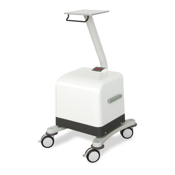
During operation, the device drains the trapped condensed water from pneumatic circuits via automatic filter separators into a separate tank. Accessories Trolley SD 30 (24) SM-DK50 DS-EN-20_02-2016... -
Page 17: Personnel
± 5% in BAR or PSI units. An indicator is lit on the display next to the relevant unit. Ask the service staff member to change the units that are shown if necessary. SM-DK50 DS-EN-20_02-2016... - Page 18 Used batteries cannot be disposed of as household waste, they must be collected separately. The condensed liquid drains into a separate tank (14) at the back of the equipment. When the tank fills up, it must be emptied. SM-DK50 DS-EN-20_02-2016...
-
Page 19: Cleaning And Replacing The Filters
Wash the filter in warm soapy water, rinse thoroughly and allow it to dry. Insert the clean filters so that the intake openings are completely covered by the filters. Cleaning the compressor To clean the compressor, use a detergent that contains no abrasives, chemical solvents or other corrosive agents. SM-DK50 DS-EN-20_02-2016... -
Page 20: Maintenance
Test the tightness of joints and after two years inspect the equipment Replace service kit A (filters) Replace service kit B 19-21 *) – The suction filter replacement interval must be shortened accordingly if used in a dusty or dirty environment! SM-DK50 DS-EN-20_02-2016... -
Page 21: Service Interval Signalization
40 µm 5 µm Number 025000018-000 025200142-000 025200113-000 typ DK50 DS basic, standard 230V Part No. 604041078-000 typ DK50 DS basic, standard 100-120V Part No. 604041079-000 typ DK50 DS advanced 230V/ 50Hz Part No. 604041091-000 typ DK50 DS advanced 100-120V Part No. -
Page 22: Maintenance Replacement Parts
Inspect the equipment: Clean and vacuum the interior of the cabinet. Check the status of the compressor motor for balanced operation or noise. Check the condition of the hangers above the pump. Check fan functionality. SM-DK50 DS-EN-20_02-2016... -
Page 23: Replacing Filters Elements
If the water release system becomes clogged, disassemble the release valve (f), clean the outlet, remove the float (b) with a lever mechanism (c, d, and e) from the tank, clean all components with a soap solution and then reassemble. SM-DK50 DS-EN-20_02-2016... -
Page 24: Output Test, Adjusting Output Pressure
Re-install components following order: (4), (3), (2) and (1) Replacing the inlet filter (21) Unlock the cover and pull it out. Replace the filter Lock the cover Spare part: Intake filter 05W POLYESTER, Item 025200194 SM-DK50 DS-EN-20_02-2016... -
Page 25: Replacing The Piston, Connecting Rod And Piston Rings
(3) and secure it with the screws (4 pcs) with washers (4 pcs). Turn the crank several times to ensure that the connecting rod moves smoothly. Attach the crankcase cover (2) using screws (6 pcs). Connect the pressure hose. Replacing the bearing: Disassembly SM-DK50 DS-EN-20_02-2016... -
Page 26: Control Electronics - 115V Version
Remove the rear panel from the compressor Disconnect the hoses, connector and wires from the printed circuit board Remove the printed circuit board and replace with a new one Reconnect the wires and connector following the electrical schematic SM-DK50 DS-EN-20_02-2016... - Page 27 SMART, if working pressure has reached 6.5 bar and now it is lower than 6.5 bar and greater than 5.0 bar, non-zero air intake is from compressor outlet – the engine works but solenoid valve is without voltage. Complete indication. SM-DK50 DS-EN-20_02-2016...
-
Page 28: Control Electronics - 230V Version
All the segments and the LEDs will light after power is connected; also the buzzer will chirp. The program version will be displayed shortly thereafter. The display will then show the outlet pressure in the units defined by the "Display PSI" jumper. The jumper position is clear from the positioning of SM-DK50 DS-EN-20_02-2016... - Page 29 4000, the value “4000” will alternate with the outlet pressure on the screen at a 2 second interval. This indicates the need for a service inspection of the compressor. The display will show the hours on the compressor motor once pressed. SM-DK50 DS-EN-20_02-2016...
- Page 30 Pressing the button alternates between the information displayed. The right edge of the display indicates the data shown. Data displayed after jumping the XP3 pins to the “Service Display” position: P1 working pressure in bar P2 outlet pressure in bar SM-DK50 DS-EN-20_02-2016...
- Page 31 After the shorted “Display PSI” jumper is inserted and removed or removed and inserted, the service hour counter is set to zero. Use the same method for setting the motor hours if the service hour counter needs to be set. SM-DK50 DS-EN-20_02-2016...
-
Page 32: Stabilizing The Compressor Before Shipping
Dispose of the equipment according to local regulations. Parts used in this product have no negative impact on the environment when disposed of properly. BATTERY DISPOSAL No battery may be disposed with common household waste. Dispose of non-functional batteries at suitable collection sites. SM-DK50 DS-EN-20_02-2016... -
Page 33: Troubleshooting
Loose (cracked) belt of the air pump metal noises) Replace damaged hanger hanger Water coming out Dirty water trap in filter and filter Clean or replace the water trap of outlets regulator Compressor Failure of control unit Adjust using service software malfunction SM-DK50 DS-EN-20_02-2016... -
Page 34: Spare Parts
Air intake filter (15 ) 025000018-000 Filtration inserts (19a) 025200142-000 Filtration inserts (19b) 025200113-000 Fuse version 230V T6,3A 038100004-000 100V, 120V T10A 038100005-000 Insertion DISS 1160-A 024000261-000 Suction filter 05W POLYESTER 025200194-000 SM-DK50 DS-EN-20_02-2016... -
Page 35: Electric And Pneumatic Diagrams
WIRING DIAGRAM 1/N/PE ~ 230/120/100 V 50..60 Hz ELECTRIC OBJECT OF 1st CAT. B TYPE DISPLAY Display Valve battery Motor 3rd contact Wiring diagram DK50 DS Mark Name Mark Name X1, X2 Sockets on PCB Electric motor EV1, EV2 Thermal sensor... -
Page 36: Pneumatic Diagram
PNEUMATIC DIAGRAM WALL 1. Suction filter 2. Compressor 3. Solenoid valve 4. Return valve 5. Cooler 6. Filter with water trap 7. Pressure regulator 8. Air outlet 9. Air inlet 10. Air tank 11. Safety valve 12. Shuttle valve SM-DK50 DS-EN-20_02-2016... -
Page 37: List Of Spare Parts
LIST OF SPARE PARTS 9. LIST OF SPARE PARTS 230V/50Hz 603011741-000 230V/50Hz 603011883-000 230V/60Hz 603011825-000 230V/60Hz 603012258-000 Air pump DK50 DS Air pump DK50 DS 115V/60Hz 603011826-000 115V/60Hz 603011957-000 Model advanced Model basic 100V/50-60Hz 603011827-000 100V/50-60Hz 603011958-000 120/60Hz 603012084-000 230V/50Hz... - Page 38 LIST OF SPARE PARTS SM-DK50 DS-EN-20_02-2016...
- Page 39 LIST OF SPARE PARTS Compressor DK50 DS Bottle cap 4KB-956 062000350-000 45 Air pump compl. Bottle LUH-1 062000333-000 Model basic 230V/50Hz 603011741-000 Check valve 3/8" MF 025300026-000 230V/60Hz 603011825-000 Foam 061000285-000 115V/60Hz 603011826-000 230V/50-60Hz 035300006-000 100V/50-60Hz 603011827-000 115V/60Hz 035300005-000 120/60Hz...
- Page 40 LIST OF SPARE PARTS Compressor DK50 DS Shuttle valve 025300082-000 Fastener 029000122-000 Angular screwing L 8/6-1/4" 025500122-000 Angular screwing 025500193-000 Coupling G1/4 FF 024000947-000 Block of filters complete 604021730-000 Switch 033500025-000 Elektronic 230V 035900085-000 Switch UL 033500032-000 - control module, batery...
- Page 41 LIST OF SPARE PARTS Compressor DK50 DS Cover complete 3BB-046 603012046-000 80 Foam 4 4KC-505 061000287-000 Foam 3 4KC-504 061000286-000 Cover 603021565-000 82 Cover back complete 3CA-339 603021339-000 Cover 062000676-000 83 Foam 6 4KC-678 061000301-000 Display cover 4KD-560 062000672-000 84...
Need help?
Do you have a question about the DK50 DS and is the answer not in the manual?
Questions and answers