Table of Contents
Advertisement
Quick Links
Advertisement
Table of Contents

Related Manuals for EKOM DK50 4x2VT/M


Summary of Contents for EKOM DK50 4x2VT/M
- Page 1 DK50 4x2VT/M DK50 6x2VT/M User manual...
- Page 3 DK50 4x2VT/M COMPRESSOR DK50 6x2VT/M EKOM spol. s r. o. Priemyselná 5031/18 SK-921 01 Piešťany Slovak Republic tel.: +421 33 7967255 fax: +421 33 7967223 www.ekom.sk email: ekom@ekom.sk DATE OF LAST REVISION 04/2022 NP-DK50-Nx2VTM-AD-EN- 6_04-2022 112000481-0001...
-
Page 4: Table Of Contents
CONTENTS CONTENTS IMPORTANT INFORMATION ....................... 5 CONFORMITY WITH THE REQUIREMENTS OF THE EUROPEAN UNION ....5 INTENDED USE ......................5 CONTRAINDICATIONS AND SIDE-EFFECTS ............... 5 SYMBOLS ........................5 WARNINGS ........................6 STORAGE AND TRANSPORT CONDITIONS ..............8 PRODUCT DESCRIPTION ......................9 VARIANTS ........................ -
Page 5: Important Information
IMPORTANT INFORMATION IMPORTANT INFORMATION 1. CONFORMITY WITH THE REQUIREMENTS OF THE EUROPEAN UNION This product conforms to the requirements of 2017/745) and is safe for the intended use if the Regulation (EU) on medical devices (MDR all safety instructions are followed. 2. -
Page 6: Warnings
IMPORTANT INFORMATION Protecting earthing Terminal for ground connection Alternating current Compressed air inlet - dryer Compressed air outlet - dryer Package handling label – fragile Package handling label – this side up Package handling label – keep dry Package handling label – temperature limits Package handling label –... - Page 7 IMPORTANT INFORMATION - the product is used pursuant to the The user must be familiar with the user manual. operation of the device. The user manual corresponds to the product configuration of the product and its environments with a risk of explosion. compliance with the applicable safety ...
-
Page 8: Storage And Transport Conditions
IMPORTANT INFORMATION 6. STORAGE AND TRANSPORT CONDITIONS compressor shipped from manufacturer in transport packaging. This The compressor is shipped in a protects the product from damage during vertical position and must be transport. secured using transport straps. Potential damage pneumatic components. Protect the compressor from humid compressor must... -
Page 9: Product Description
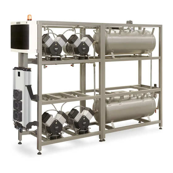
PRODUCT DESCRIPTION PRODUCT DESCRIPTION 7. VARIANTS The compressor is manufactured according to its intended application in the following variants: DK50 4x2VT/M Composed of modules: compressor module - 4x2V air pumps adsorption dryer air tank module – 2x110 l DK50 6x2VT/M... - Page 10 PRODUCT DESCRIPTION DK 50 6x2VT/M NP-DK50-Nx2VTM-AD-EN-6_04-2022 04/2022...
-
Page 11: Accessories
PRODUCT DESCRIPTION 8. ACCESSORIES Accessories that are not included in the filter sets are identical for the DK50 4x2VT/M standard order must be ordered separately. and DK50 6x2VT/M products. Where a different level of air Set of compressed air outlet filters... -
Page 12: Product Function
PRODUCT DESCRIPTION 9. PRODUCT FUNCTION separator (29), entering the active chamber 9.1. Compressor with adsorption with adsorbent (19), where the air is then dryer dried. A portion of the dry air is fed into the The compressor air pumps (1) draw in air second, regeneration chamber, where this air through the inlet filter (8) and compress it is used to remove moisture from the... - Page 13 PRODUCT DESCRIPTION Fig. 1: Compressor with adsorption dryer 04/2022 NP-DK50-Nx2VTM-AD-EN-6_04-2022...
- Page 14 PRODUCT DESCRIPTION Fig. 2: Adsorption dryer NP-DK50-Nx2VTM-AD-EN-6_04-2022 04/2022...
- Page 15 PRODUCT DESCRIPTION Fig. 3: Electrical box / switchboard The range of the pressure Pressure in the compressed air switch configured circuit only increase assemblies only because of an increase in flow adjusted after prior resistance in the compressed consultation with air lines or as a result of a dryer manufacturer.
-
Page 16: Technical Data
TECHNICAL DATA TECHNICAL DATA Compressors are designed for operation in dry, ventilated and dust-free indoor rooms under the following climactic conditions: +5°C to +40°C Temperature Relative humidity max. 70% Working pressure 6 – 8 bar DK50 6x2VT/M Rated voltage V, Hz 3x400, 50 Frequency Capacity at 6 bar (FAD) -20°C... - Page 17 TECHNICAL DATA Dependence of compressor output on working pressure 04/2022 NP-DK50-Nx2VTM-AD-EN-6_04-2022...
- Page 18 TECHNICAL DATA Working pressure 6 – 8 bar DK50 4x2VT/M DK50 6x2VT/M Rated voltage V, Hz 3x400, 50 3x400, 50 Frequency Output at 6 bar (FAD) at PDP-40°C l/min 6.0 – 8.0 6.0 – 8.0 Working pressure Rated current 14.5...
- Page 19 TECHNICAL DATA Working pressure 8 – 10 bar DK50 6x2VT/M Rated voltage V, Hz 3x400, 50 Frequency Output at 6 bar (FAD) at PDP-20°C l/min 8.0 – 10.0 Working pressure Rated current Main circuit protection device rating Main electrical feeder Enclosure IP10 Motor output...
- Page 20 TECHNICAL DATA Working pressure 8 – 10 bar DK50 4x2VT/M DK50 6x2VT/M Rated voltage V, Hz 3x400, 50 3x400, 50 Frequency Output at 8 bar (FAD) at PDP-40°C l/min 8.0 – 10.0 8.0 – 10.0 Working pressure Rated current 15.5...
- Page 21 TECHNICAL DATA FAD correction of capacity for altitude Capacity given in the form of FAD („Free Air Delivery“) applies to the following conditions: 20°C Altitude 0 m.n.m. Temperature Atmospheric pressure 101325 Pa Relative humidity To calculate FAD compressor capacity in dependence on altitude, it is necessary to apply correction factor according to the following table: Altitude [m.n.m.] 0 -1500...
-
Page 22: Installation
INSTALLATION INSTALLATION Risk of incorrect installation. Only a qualified technician may install the compressor place it into operation for the first time. Their duty is to train operating personnel on the use maintenance equipment. An entry is made in equipment installation record to certify installation and operator... -
Page 23: Compressor Assembly
Space conditions Temperature +5°C ÷ +40°C Relative humidity 70% Recommended flow of cooling air: DK50 6x2VT/M - 1500m DK50 4x2VT/M – 1000m Applies for continuous operation and cooling air temperature of 20°C Cooling air inlet 11. COMPRESSOR ASSEMBLY are secured to pallets. - Page 24 INSTALLATION Fig. 5: Handling the compressor module Fig. 6: Levelling the compressor Fig. 7:Frame installation NP-DK50-Nx2VTM-AD-EN-6_04-2022 04/2022...
- Page 25 Remove the transport stabilisers from the air pumps (X, Y, Z) (Fig. 8). At least two persons are needed DK50 4x2VT/M – 8x mounts. to handle the equipment. DK50 6x2VT/M – 12x mounts Integrated handles are installed on the lower brackets on the product.
-
Page 26: Pneumatic Connection
INSTALLATION Fig. 9: Handling the dryer High temperature hazard The placement of air flow impediments upstream or downstream of the cooler is prohibited. The temperature of the internal and external parts of the cooler may be hot and reach hazardous temperatures. 12. - Page 27 INSTALLATION Fig. 11: Pneumatic connection AD dryer compressed air inlet Connect the outlet (OUT) from the compressor’s manifold to the inlet (AIR IN) on the dryer (1). Use the 950 mm hose. Fig. 12: Compressed air inlet 04/2022 NP-DK50-Nx2VTM-AD-EN-6_04-2022...
- Page 28 INSTALLATION Burn or fire hazard! Caution! Hot surface! When installing the connecting hoses at the inlet to the air dryer, ensure that temperature is not hazardous if it was to come into contact with an operator or other material. AD dryer compressed air outlet ...
-
Page 29: Electrical Connection
INSTALLATION A G3/4” (F) ball valve is installed on the compressed air outlet from the air tank. Fig. 15: Air outlet from the air tank Potential damage pneumatic components. Ensure the air hoses are not kinked. 13. ELECTRICAL CONNECTION Unauthorised interference product delivered... - Page 30 INSTALLATION Fig. 17: Connecting the electrical cables Connect disconnected electrical cables (E) to the terminal strips in the electric motor boxes. Insert the cables into the electrical installation trays and enclose with a cover. Fig. 18: Connecting the power cord ...
-
Page 31: Commissioning
INSTALLATION Fig. 20: Connecting the control harness and power cord from the compressor Connect the dryer control and power cord from the compressor to the receptacle (1). Fire hazard and risk of electric shock. Ensure the electrical cable does not touch hot parts of the device or connecting hoses. -
Page 32: Pneumatic Diagrams
INSTALLATION 15. PNEUMATIC DIAGRAMS DK50 4x2VT/M NP-DK50-Nx2VTM-AD-EN-6_04-2022 04/2022... - Page 33 INSTALLATION DK50 6x2VT/M 04/2022 NP-DK50-Nx2VTM-AD-EN-6_04-2022...
- Page 34 INSTALLATION Description to pneumatic diagrams: 1. Inlet filter 11. Pressure gauge 2. Air pump 12. Cooler 3. Compressor fan 13. Cooler fan 4. Solenoid valve 14. Air tank 5. Safety valve 15. Condensate drain valve 6. Non-return valve 16. Outlet valve 7.
-
Page 35: Operation
OPERATION OPERATION ONLY TRAINED PERSONNEL Potential damage OPERATE pneumatic components. EQUIPMENT! The working pressure settings for the pressure switch set by the manufacturer cannot be Risk of electric shock. changed. Compressor case emergency, operation at a working pressure disconnect compressor below the switching pressure from the mains (pull out the indicates high air usage (see the... -
Page 36: Switching The Compressor
OPERATION 16. SWITCHING THE COMPRESSOR After the pressure switch (6) is activated and fans, switching them off once the temperature circuit breakers FA13 (11) and FA14 (12) are decreases to approximately 32 turned to position I, the compressor air pumps 16.1. - Page 37 OPERATION A menu appears press ▲ or ▼ to select the day of the week press ► or ◄ to move the cursor to the next position press ▲ or ▼ to set the desired value repeat the previous two steps to set the date and time ...
- Page 38 OPERATION Low priority alarm conditions etc.). maintenance specific components pursuant to the attached Table 2 The equipment is equipped to monitor and must be performed once a maintenance signal maintenance intervals. Maintenance interval is passed. This condition is indicated intervals are whole number multiples of 2000 by an activated yellow HA beacon and an operating hours I = n x 2000 hours (n = 1, 2, information message on the display.
-
Page 39: Switching Off The Compressor
OPERATION Alarm signals have priority over maintenance interval signals. As such, the light will indicate an alarm from any of the air pumps. One the alarm is over, the service interval is indicated by the activated HA beacon. 17. SWITCHING OFF THE COMPRESSOR Turn off the controller program for maintenance or other reasons that require the controller be shut down. -
Page 40: Product Maintenance
PRODUCT MAINTENANCE PRODUCT MAINTENANCE 18. PRODUCT MAINTENANCE The operator shall secure the Danger of injury or equipment completion of repeated testing damage. of the equipment at least once Prior commencing every 24 months (EN 62353) or compressor maintenance, it is at the intervals defined by the necessary to: applicable national regulations. - Page 41 PRODUCT MAINTENANCE Burn hazard. The work below may only be performed by trained personnel as follows: When compressor running or shortly thereafter, Turn off the circuit breakers at certain portions of the air pump, the switchboard before starting the compressor’s compressed any subsequent maintenance air system, parts of the dryer work.
- Page 42 PRODUCT MAINTENANCE 18.1. Maintenance intervals operator qualified technician NP-DK50-Nx2VTM-AD-EN-6_04-2022 04/2022...
- Page 43 PRODUCT MAINTENANCE qualified technician 04/2022 NP-DK50-Nx2VTM-AD-EN-6_04-2022...
- Page 44 PRODUCT MAINTENANCE running during defined 18.2. Check of product operation compressor work cycles. Check air pump condition – the Check the filter condition – clean dirty aggregates should operating filters or replace with new filters. normally without excessive vibration or ...
- Page 45 PRODUCT MAINTENANCE Condensate from compressors with air dryers is automatically drained into a vessel to collect condensate. Monitor the level in the vessel using the markings (depending on the volume of the vessel), and empty at least once a day. Fig.
- Page 46 PRODUCT MAINTENANCE Turn the screw on the safety valve several rotations to the left until the safety valve releases air. Let the safety valve vent for only a few seconds. Turn the screw to the right until it seats, closing the valve.
- Page 47 PRODUCT MAINTENANCE 18.10. Check of solenoid valve operation Check their operation using the “Magnetic indicator” fixture as follows: Attach the fixture to the valve coil and if the motors are active at the valve coil, the indicator must rotate and if they are out of inactive, the indicator must not rotate.
- Page 48 PRODUCT MAINTENANCE Fig. 25: Venting pressure from the dryer chambers Disconnect the hose (2) from the lower part of the condensate separator (3) (Fig. 26). Fig. 26: Venting pressure from the cooler and condensate separator The process of manually venting pressure Prior to any work, disconnect the equipment from the mains, from...
- Page 49 PRODUCT MAINTENANCE Turn off the compressor. Check the pressure in the dryer. If the dryer chambers are under pressure, proceed in accordance with Chapter 18.13. Unscrew the 8 screws (1). Disassemble the outlet panel (2) on which the filters (3) are mounted.
- Page 50 PRODUCT MAINTENANCE 18.16. Replacement of the logic valve ball Turn off the compressor. Check the pressure in the dryer. If the dryer chambers are under pressure, proceed in accordance with Chapter 18.13. Unscrew the 4 screws (1) and remove the cover (2).
- Page 51 PRODUCT MAINTENANCE Check the pressure in the dryer. 18.18. Inspecting the cooler and fan If the dryer chambers are under The equipment, in particular the compressor pressure, proceed in accordance with fan, cooler fan, and the cooler, must be kept Chapter 18.13.
- Page 52 PRODUCT MAINTENANCE Fig. 31: Solenoid valve replacement nut (4-6). Solenoid valve assembly Insert the valve membrane spring (4- Replacement solenoid valves are delivered as 3) into the membrane (4-2) and the disassembled replacement parts. The new insert into the assembled valve coil valve must be assembled before a solenoid and body assembly.
- Page 53 PRODUCT MAINTENANCE pressure 18.20. Pressure relief valve compressed air circuit can only The pressure relief valve automatically begins increase because of an increase to vent air from the system if the pressure in flow resistance the compressed air circuit exceeds its pre-set compressed air lines or as a value.
-
Page 54: Troubleshooting
TROUBLESHOOTING TROUBLESHOOTING Risk of electric shock. Troubleshooting may only be performed qualified Before interfering with service technician. equipment, first disconnect it from the mains (remove the power socket). Damage to the safety valve could cause pressure to rise to hazardous levels. Working with pressurised... - Page 55 TROUBLESHOOTING Leak through solenoid valves once Clean the check valve - replace if regeneration is complete damaged Leak at pressure sensor and safety Test their function and clean, or replace valve if damaged Check connections on the air pump for Air pump leaking leaks –...
-
Page 56: Repair Service
TROUBLESHOOTING Check the moisture content of the air exiting the air tank (see the Technical data chapter) to prevent damage to connected downstream equipment. 19. REPAIR SERVICE Warranty and post-warranty repairs must be The manufacturer reserves the right to make done by the manufacturer, its authorized changes to the equipment without notice. -
Page 57: Annex
ANNEX ANNEX 22. INSTALLATION RECORD 1. Product: (model) 2. Serial number: DK50 4X2VT/M DK50 6x2VT/M 3.1. User’s name: 3.2. Address of installation: 4. Equipment connected to the compressor: 5. Installation / Commissioning: 6. Contents of operator training: Product completeness check **... - Page 60 DK50 4x2VT/M DK50 6x2VT/M EKOM spol. s r.o., Priemyselná 5031/18, 921 01 PIEŠŤANY, Slovak Republic tel.: +421 33 7967255, fax: +421 33 7967223 e-mail: ekom@ekom.sk, www.ekom.sk NP-DK50-Nx2VTM-AD-EN-6_04-2022 112000481-0001...
Need help?
Do you have a question about the DK50 4x2VT/M and is the answer not in the manual?
Questions and answers