EKOM DK50 2x4VR/110/M User Manual
Hide thumbs
Also See for DK50 2x4VR/110/M:
- User manual (524 pages) ,
- Installation, operation and maintenance manual (30 pages) ,
- User manual (220 pages)
Table of Contents
Advertisement
Available languages
Available languages
Quick Links
Advertisement
Chapters
Table of Contents

Related Manuals for EKOM DK50 2x4VR/110/M


Summary of Contents for EKOM DK50 2x4VR/110/M
- Page 1 DK50 2x4VR/110 User manual Benutzerhandbuch Návod na použitie...
- Page 3 COMPRESSOR KOMPRESSOR DK50 2x4VR/110/M KOMPRESOR EKOM spol. s r. o. Priemyselná 5031/18 SK-921 01 Piešťany Slovak Republic tel.: +421 33 7967255 fax: +421 33 7967223 www.ekom.sk email: ekom@ekom.sk DATE OF LAST REVISION DATUM DER LETZTEN ÜBERARBEITUNG 09/2020 DÁTUM POSLEDNEJ REVÍZIE...
- Page 4 CONTENTS ....................4 INHALT ......................57 OBSAH ......................111...
-
Page 5: Table Of Contents
CONTENTS CONTENTS GENERAL INFORMATION ......................6 CONFORMITY WITH THE REQUIREMENTS OF THE EUROPEAN UNION ....6 SYMBOLS ........................6 DEVICE USE ........................7 GENERAL SAFETY INSTRUCTIONS ................8 STORAGE AND TRANSPORT CINDITIONS ..............9 PRODUCT DESCRIPTION ......................10 VARIANTS ........................10 ACCESSORIES ...................... -
Page 6: General Information
GENERAL INFORMATION GENERAL INFORMATION Carefully read this user manual before using the product and carefully store it for future reference. The user manual aids in the proper use, including installation, operation and maintenance, of the product. The user manual corresponds to the configuration of the product and its compliance with applicable safety and technical standards at the time of its printing. -
Page 7: Device Use
GENERAL INFORMATION Compressed air inlet Compressed air outlet Control wire input Package handling label – fragile Package handling label – this side up Package handling label – keep dry Package handling label – temperature limits Package handling label – limited stacking Package label –... -
Page 8: General Safety Instructions
GENERAL INFORMATION 4. GENERAL SAFETY INSTRUCTIONS The product is designed and manufactured so that any risks connected with its use are minimized and the product is safe for the user and surrounding when used according to the intended use and the instructions stated below are followed. -
Page 9: Storage And Transport Cinditions
GENERAL INFORMATION 5. STORAGE AND TRANSPORT CINDITIONS The compressor is shipped from the manufacturer in transport packaging. This protects the product from damage during transport. Potential for damage to pneumatic components. The compressor must be transported only when all air has been vented. Before moving or transporting the compressor, release all the air pressure from the tank and pressure hoses, from dryer chambers and drain condensate from the tank and from the condensate separator on the dryer. -
Page 10: Product Description
PRODUCT DESCRIPTION PRODUCT DESCRIPTION 6. VARIANTS The compressor is manufactured according to its intended application in the following variants: DK50 2x4VR/110/M Compressor with adsorption dryer DK50 2x4VR/110S/M Compressor in cabinet with adsorption dryer Cabinet S110R It decreases noise level of the compressor. -
Page 11: Accessories
The regulator must be selected according to the application to the filter set, or separately The regulator shall ensure constant pressure at the outlet. Type Article number Regulator complete 604014125-000 DK50 2x4VR/110/M REG15 447000001-243 Filter set brackets A suitable bracket must be ordered for every filter set. Type... - Page 12 PRODUCT DESCRIPTION 8.2. Compressor cabinet The soundproof cabinet provides compact covering of the compressor, dampens noise efficiently, providing sufficient exchange of cooling air. The fan (10) under the compressor pump provides cooling of the compressor. It is in operation at the same time with the compressor motor or after switching on the temperature switch at temperature above 40°C.
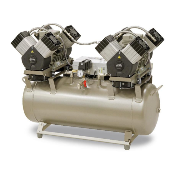
- Page 13 PRODUCT DESCRIPTION Fig. 1: DK50 2x4VR/110/M – Compressor with adsorption dryer 09/2020 NP-DK50 2x4VR 110-AD-A-1_09-2020...
- Page 14 PRODUCT DESCRIPTION Fig. 2: Adsorption dryer NP-DK50 2x4VR 110-AD-A-1_09-2020 09/2020...
- Page 15 PRODUCT DESCRIPTION Fig. 3: Cabinet 09/2020 NP-DK50 2x4VR 110-AD-A-1_09-2020...
-
Page 16: Technical Data
Compressors are designed for operation in dry, ventilated and dust-free indoor rooms under the following climactic conditions: +5°C to +40°C Temperature Relative humidity max. 70% Working pressure 6 – 8 bar DK50 2x4VR/110/M DK50 2x4VR/110S/M Nominal voltage V, Hz 3x400V, 50Hz 3x400V, 50Hz Frequency... - Page 17 TECHNICAL DATA Working pressure 8 – 10 bar DK50 2x4VR/110/M DK50 2x4VR/110S/M Nominal voltage V, Hz 3x400, 50 3x400 , 50 Frequency Capacity at 8 bar l/min (FAD) -20°C 8.0 – 10.0 8.0 – 10.0 Working pressure Max. current 10.2 Motor power 2x2.2...
- Page 18 TECHNICAL DATA FAD correction of capacity for altitude Capacity given in the form of FAD („Free Air Delivery“) applies to the following conditions: 20°C Altitude 0 m.n.m. Temperature Atmospheric pressure 101325 Pa Relative humidity To calculate FAD compressor capacity in dependence on altitude, it is necessary to apply correction factor according to the following table: Altitude [m.n.m.] 0 -1500...
-
Page 19: Installation
INSTALLATION INSTALLATION Risk of incorrect installation. Only a qualified technician may install the compressor and place it into operation for the first time. Their duty is to train operating personnel on the use and maintenance of the equipment. An entry is made in the equipment installation record to certify installation and operator training. - Page 20 INSTALLATION Fig. 4: Handling the compressor Remove the transport stabilisers from the air pumps (Fig. 5). Prior to installation, ensure that the compressor is free of all transport packaging and stabilizers to avoid any risk of damage to the product. Remove all devices used to secure the aggregates once the compressor is installed and levelled at the site of final installation.
- Page 21 INSTALLATION Fig. 6: Handling the dryer 10.2. Placement of the compressor in the cabinet Opening the upper cover Open the lock by turning with a screwdriver as shown in the pictogram and pick up using the handle. The gas springs will keep the cover open. Be careful not to pinch your fingers when closing the cover on the cabinet.
-
Page 22: Pneumatic Connection
INSTALLATION 11. PNEUMATIC CONNECTION 11.1. Connecting the dryer AD dryer compressed air inlet Connect the compressed air outlet from the compressor to the dryer inlet (1). Use the shorter of the provided hoses. (2200 mm) A G 3/4" connection is installed. Fig. - Page 23 INSTALLATION AD dryer compressed air outlet Connect the outlet from the dryer (1) to the air inlet on the air tank. Use the longer of the provided hoses. (2900 mm) A G 3/4” connection is installed. Fig. 9: Compressed air outlet ...
- Page 24 INSTALLATION Connecting hose (A) is routed from the compressor outlet (1) to the dryer inlet (2) and is routed together with hose B using double clips (3). Connecting hose (B) is routed from the dryer outlet (4) to the air tank inlet (5) and is connected to the dryer (6) using clips.
- Page 25 INSTALLATION Condensate outlet from dryer Connect a hose to the outlet (1) from the automatic condensate drain (2) to drain piping or to the provided collection vessel. A noise silencer is recommended when connecting directly to drain piping. Fig. 13: Condensate drain 11.2.
-
Page 26: Electrical Connection
INSTALLATION 11.3. Connecting the cabinet pressure gauge to the compressor Remove the plug (1) from the threads (2) on the pneumatic block of the compressor Connect the cabinet pressure gauge hose to the threaded fitting Fig. 15: Connecting the cabinet pressure gauge to the compressor 11.4. - Page 27 INSTALLATION Fig. 16: Connecting the control harness and power cord Risk of fire and electric shock. Electrical cable must not be in contact with hot compressor components. Connect the pin for equipotential bonding 6 mm (1) to the electrical circuit using the defined method under valid...
- Page 28 INSTALLATION Fig. 18: Connect the cabinet to the compressor Ethernet connection The dryer may be connected to an Ethernet 10/100 M network via the controller as follows: Connect the Ethernet network cable to the RJ-45 connector on the rear of the dryer. ...
- Page 29 INSTALLATION Open the web browser on a PC, smartphone or tablet and enter the IP address of the controller (in this case 192.168.0.3). Enter the password “LOGO” and click on the “LOG on” button. After logging in, the browser displays the first screen showing the system information for the controller itself: module...
-
Page 30: Commissioning
INSTALLATION 13. COMMISSIONING Make sure all transport stabilizers were removed. Check that all compressed air hose connections are correct Check correct connection to the mains (see chap. 12). Check the circuit breaker position, it must be in the “I” position. If the main switch (2) is in the “0” position, turn it to the “I”... -
Page 31: Pneumatic And Electrical Diagrams
INSTALLATION 14. PNEUMATIC AND ELECTRICAL DIAGRAMS 14.1. Pneumatic diagram DK50 2x4VR/110/M 09/2020 NP-DK50 2x4VR 110-AD-A-1_09-2020... - Page 32 24 Inlet filter 12 Cooler 25 Chamber left 13 Dryer solenoid valve 26 Chamber right 14.2. Electrical diagrams DK50 2x4VR/110/M 6 - 8 bar, 8 - 10 bar 3/N/PE~400V, 50Hz ELEKTRIC MAIN TN-S [TN-C-S] ELEKTRIC OBJECT OF 1st. CAT. NP-DK50 2x4VR 110-AD-A-1_09-2020...
- Page 33 INSTALLATION DK50 2x4VR/110S/M Description to electrical diagrams: M1, M2 Compressor motor X2, X3 Socket E1, E2 Compressor fan Pressure switch E3, E4 Compressor fan C10,11 Capacitor E10, E11 Cabinet fan Fuse Temperature switch Hour counter Q11, Q12 Contactor K1, K2 Time relay F1,2 Breaker...
-
Page 34: Operation
OPERATION OPERATION ONLY TRAINED PERSONNEL MAY OPERATE THE EQUIPMENT! Risk of electric shock. In case of emergency, disconnect the compressor from the mains (pull out the mains plug). Burn or fire hazard. Portions of the aggregate and compressed air components between the aggregate and the air cooler may be hot and reach hazardous temperatures during compressor operation that may harm materials or operating staff. -
Page 35: Switching On The Compressor
OPERATION 15. SWITCHING ON THE COMPRESSOR Start the compressor (without a cabinet) at the pressure switch (1) by turning the switch (2) to position “I.” This starts the compressor and fills the tank to the switching off pressure, which then shuts off the compressor. - Page 36 OPERATION Valve switching schedule – “RUN” mode "STANDBY” mode The dryer is in “STANDBY” mode when the control signal from the compressor is inactive. The cooling fans are off and chamber switching is deactivated. AD500 SE dryer display Home screen ...
- Page 37 OPERATION “RUN MODE” screen TOTAL HRS – total time the dryer has been energised RUN HRS – total dryer cycling time TME-to-MT – time until the service interval expires “STAND BY MODE” screen TOTAL HRS – total time the dryer has been energised ...
-
Page 38: Product Maintenance
PRODUCT MAINTENANCE PRODUCT MAINTENANCE 18. PRODUCT MAINTENANCE The operator should carry out device checks regularly in the intervals defined by applicable regulations. Test results must be recorded. The equipment has been designed and manufactured to keep maintenance to a minimum. The following work must be performed to preserve the proper and reliable operation of the compressor. - Page 39 PRODUCT MAINTENANCE 18.1. Maintenance intervals operator qualified technician 09/2020 NP-DK50 2x4VR 110-AD-A-1_09-2020...
- Page 40 PRODUCT MAINTENANCE qualified technician NP-DK50 2x4VR 110-AD-A-1_09-2020 09/2020...
- Page 41 PRODUCT MAINTENANCE 18.2. Check of product operation Check aggregate condition – the aggregates should be operating normally without excessive vibration or noise. Troubleshoot any problem or call in service personnel if trouble is detected. Visually inspect fan operation – the fans must be operating when the aggregates are running. Troubleshoot any problem or call in service personnel if trouble is detected.
- Page 42 PRODUCT MAINTENANCE Visually check if cables are connected to the terminal box. Check all screw connections of the green-yellow PE grounding conductor. Checking the operating condition of the AD dryer Check the service indicator and alarms on the display screen as specified in Chapter 17 and schedule service or repairs as needed.
- Page 43 PRODUCT MAINTENANCE ESC+▲– “OPERATING TIME” screen information on operating hours: TOTAL, RUN, STAND BY, time remaining to the next service interval and value of the defined service interval TOTAL HRS – total time the dryer has been energised RUN HRS – total dryer cycling time STAND.HRS –...
- Page 44 PRODUCT MAINTENANCE 18.6. Check of safety valve Turn the screw (2) on the safety valve (1) several times to the left until the safety valve releases the air. Let the safety valve vent for a few seconds. Turn the screw (2) fully to the right, the valve must be closed now.
- Page 45 PRODUCT MAINTENANCE 18.8. Procedure for connecting a compressor disconnected from the cabinet Prior to any maintenance or repair work, switch off the compressor and disconnect it from the mains (pull out the mains plug). The compressor (without cabinet) requires that the jumper is always mounted in the terminal strip for correct operation (Fig.
- Page 46 PRODUCT MAINTENANCE 400 V 18.9. Procedure for connecting a compressor to a new cabinet Prior to any maintenance or repair work, switch off the compressor and disconnect it from the mains (pull out the mains plug). The compressor in a cabinet requires that the jumper is not mounted in the terminal strip for correct operation (Fig.
- Page 47 PRODUCT MAINTENANCE Connect the cabinet to the compressor by inserting the power cord with connector into a power socket. (Fig. 18) Connect the device to the electrical mains Activate the compressor by turning on the switch on the pressure switch and the switch (4) on the cabinet (Fig.
- Page 48 PRODUCT MAINTENANCE Fig. 25: Venting pressure from the dryer chambers Disconnect the hose (2) from the lower part of the condensate separator (3) (Fig. 26). Fig. 26: Venting pressure from the cooler and condensate separator The process of manually venting pressure from the equipment is complete after approximately 2 minutes.
- Page 49 PRODUCT MAINTENANCE Turn off the compressor. Check the pressure in the dryer. If the dryer chambers are under pressure, proceed in accordance with Chapter 18.11. Unscrew the 8 screws (1). Disassemble the outlet panel (2) on which the filters (3) are mounted.
- Page 50 PRODUCT MAINTENANCE 18.14. Replacement of the logic valve ball Turn off the compressor. Check the pressure in the dryer. If the dryer chambers are under pressure, proceed in accordance with Chapter 18.11. Unscrew the 4 screws (1) and remove the cover (2).
- Page 51 PRODUCT MAINTENANCE 18.17. Replacement of solenoid valves Risk of electric shock. Shut off the compressed air source, turn off the equipment and disconnect it from the mains before working on the equipment. Working with pressurised pneumatic components poses a risk of injury. Disconnect the equipment from the mains and vent the pressure in the equipment and the pneumatic system to zero before working on the equipment.
- Page 52 PRODUCT MAINTENANCE Fig. 31: Solenoid valve replacement Solenoid valve assembly Replacement solenoid valves are delivered as disassembled replacement parts. The new valve must be assembled before a solenoid valve is replaced. Mount the valve coil (4-5) onto the valve body (4-4) and secure with the nut (4-6). ...
-
Page 53: Long-Term Shutdown
PRODUCT MAINTENANCE compressed air circuit exceeds its pre-set value. The pressure relief valve closes as the pressure drops. The pressure in the compressed air circuit can only increase because of an increase in flow resistance in the compressed air lines or as a result of a dryer malfunction (e.g. -
Page 54: Troubleshooting
TROUBLESHOOTING TROUBLESHOOTING Risk of electric shock. Before interfering with the equipment, first disconnect it from the mains (remove the power socket). Working with pressurised pneumatic components poses a risk of injury. Before interfering with the equipment, vent the air tank and the compressed air system to zero pressure. - Page 55 TROUBLESHOOTING compressor Worn piston ring Replace worn piston ring Dirty inlet filter Replace dirty filter with new filter Incorrect function of solenoid valve Repair or replace fan or coil Compressor is Damaged piston bearing, piston Replace damaged bearing noisy (knocking, rods, motor bearing metal noises) Loose (cracked) dampening...
-
Page 56: Repair Service
TROUBLESHOOTING Once a dryer fault is cleared and after its reassembly, the dryer should quickly be regenerated, best when using continuous compressor operation at a pressure of around 1 bar for a period of at least 1 hour; then check the dryness of the compressed air. Check the moisture content of the air exiting the air tank (see the Technical data chapter) to prevent damage to connected downstream equipment. - Page 57 INHALT INHALT ALLGEMEINE INFORMATIONEN ....................58 KONFORMITÄT MIT DEN ANFORDERUNGEN DER EU ..........58 SYMBOLE ........................58 NUTZUNG DES GERÄTS ....................59 ALLGEMEINE SICHERHEITSANWEISUNGEN ............. 60 LAGERUNGS- UND TRANSPORTBEDINGUNGEN ............61 PRODUKTBESCHREIBUNG ....................... 62 VERSIONEN ........................62 ZUBEHÖR ........................63 PRODUKTFUNKTION ....................
-
Page 58: Allgemeine Informationen
ALLGEMEINE INFORMATIONEN ALLGEMEINE INFORMATIONEN Lesen Sie das Benutzerhandbuch vor der Nutzung des Produkts sorgfältig durch und bewahren Sie es auf. Das Benutzerhandbuch enthält Anleitungen zur korrekten Nutzung, Installation, Bedienung und Wartung des Produkts. Zum Zeitpunkt des Drucks entspricht das Benutzerhandbuch dem Produktdesign und erfüllt die geltenden Sicherheits- und Technikstandards. -
Page 59: Nutzung Des Geräts
ALLGEMEINE INFORMATIONEN Sicherung Drucklufteingang Druckluftausgang Eingang Steuerdraht Etikett für die Handhabung der Verpackung – zerbrechlich Etikett für die Handhabung der Verpackung – diese Seite nach oben Etikett für die Handhabung der Verpackung – trocken lagern Etikett für die Handhabung der Verpackung – Temperaturgrenzwerte Etikett für die Handhabung der Verpackung –... -
Page 60: Allgemeine Sicherheitsanweisungen
ALLGEMEINE INFORMATIONEN Der Kompressor darf nur unter den Bedingungen verwendet werden, die im Abschnitt Technische Daten aufgeführt sind. Eine Nutzung des Produkts über die bestimmungsgemäße Verwendung hinaus gilt als unsachgemäße Nutzung. Der Hersteller haftet nicht für Schäden oder Verletzungen durch eine unsachgemäße Nutzung oder durch die Nichtbeachtung der Anweisungen in diesem Benutzerhandbuch. -
Page 61: Lagerungs- Und Transportbedingungen
ALLGEMEINE INFORMATIONEN reibungslose Funktion des Produkts. Es dürfen nur Zubehör- und Ersatzteile verwendet werden, die in der technischen Dokumentation genannt werden oder ausdrücklich vom Hersteller zugelassen sind. Die Garantie deckt keine Schäden aufgrund einer Verwendung anderer Zubehör- und Ersatzteile als den vom Hersteller genannten oder empfohlenen ab und der Hersteller haftet hierfür nicht. -
Page 62: Produktbeschreibung
PRODUKTBESCHREIBUNG PRODUKTBESCHREIBUNG 6. VERSIONEN Der Kompressor ist gemäß seinem Verwendungszweck in den folgenden Modellen erhältlich: DK50 2x4VR/110/M Kompressor mit Adsorptionstrockner Kompressor im Gehäuse mit Adsorptionstrockner DK50 2x4VR/110S/M Gehäuse S110R Reduziert den Geräuschpegel des Kompressors DK50 2x4VR/110/M S110R DK50 2x4VR/110S/M NP-DK50 2x4VR 110-AD-A-1_09-2020... -
Page 63: Zubehör
Der Regler muss entsprechend der Anwendung auf den Filtersatz oder separat ausgewählt werden. Der Regler muss einen konstanten Druck am Auslass gewährleisten. Verwendung Artikelnummer Druckregler 604014125-000 DK50 2x4VR/110/M 447000001-243 REG15 Filtersatz Halterungen Für jeden Filtersatz muss eine passende Halterung bestellt werden. Verwendung Artikelnummer Halterung für Kompressormontage... - Page 64 PRODUKTBESCHREIBUNG Kompressorgehäuse 8.2. Das schalldichte Gehäuse dient zur kompakten Abdeckung des Kompressors. Gleichzeitig gewährt es einen ausreichenden Luftaustausch und dämpft Geräusche wirkungsvoll. Der Lüfter (10) unter der Kompressorpumpe kühlt den Kompressor. Er läuft gleichzeitig mit dem Kompressormotor oder nach dem Einschalten des Temperaturschalters bei einer Temperatur von über 40 °C. Nachdem der Gehäusebereich auf weniger als ca.
- Page 65 PRODUKTBESCHREIBUNG Abb. 1: DK50 2x4VR/110/M – Kompressor mit Adsorptionstrockner 09/2020 NP-DK50 2x4VR 110-AD-A-1_09-2020...
- Page 66 PRODUKTBESCHREIBUNG Abb. 2: Adsorptionstrockner NP-DK50 2x4VR 110-AD-A-1_09-2020 09/2020...
- Page 67 PRODUKTBESCHREIBUNG Abb. 3: Gehäuse 09/2020 NP-DK50 2x4VR 110-AD-A-1_09-2020...
-
Page 68: Technische Daten
Die Kompressoren sind für den Betrieb in trockenen, belüfteten und staubfreien Innenräumen unter den folgenden klimatischen Bedingungen vorgesehen: +5 °C bis +40 °C Temperatur Relative Feuchtigkeit max. 70 % Arbeitsdruck 6 bis 8 bar DK50 2x4VR/110/M DK50 2x4VR/110S/M Nennspannung V, Hz 3x400V, 50Hz 3x400V, 50Hz Frequenz Kapazität bei 6 bar... - Page 69 TECHNISCHE DATEN Arbeitsdruck 8 bis 10 bar DK50 2x4VR/110/M DK50 2x4VR/110S/M Nennspannung V, Hz 3x400, 50 3x400 , 50 Frequenz Kapazität bei 8 bar l/min (FAD) –20 °C 8,0 – 10,0 8,0 – 10,0 Arbeitsdruck Max. Strom 10,2 Motorleistung 2x2.2 2x2.2...
- Page 70 TECHNISCHE DATEN FAD-Kapazitätskorrektur für Höhenlagen Die Kapazität in Form von FAD („Free Air Delivery“ = Volumenstrom bzw. Liefermenge) gilt für die folgenden Bedingungen: Höhenlage 0 m ü. M. 20 °C Temperatur Umgebungsdruck 101325 Pa Relative Feuchtigkeit Um die FAD-Kompressorkapazität in Abhängigkeit von der Höhenlage zu berechnen, muss der Korrekturfaktor gemäß...
-
Page 71: Installation
INSTALLATION INSTALLATION Risiko von Installationsfehlern Der Kompressor darf nur durch einen hierfür qualifizierten Techniker installiert und in Betrieb genommen werden. Dieser ist verpflichtet, professionelles Bedienpersonal bzgl. der Nutzung und Wartung der Gerätschaften zu schulen. Für den Nachweis einer Installations- und Bedienerschulung erfolgt ein Eintrag in das Installationsprotokoll der Gerätschaft. - Page 72 INSTALLATION Abb. 4: Handhabung des Kompressors Entfernen Sie die Transporthilfen aus den Druckluftpumpen (Abb. 5). Stellen Sie vor der Installation sicher, dass der Kompressor frei von Verpackungsmaterial und Stabilisatoren ist, um Schäden am Produkt zu vermeiden. Entfernen Sie alle für die Sicherung der Aggregate verwendeten Komponenten, nachdem der Kompressor am endgültigen Einsatzort installiert und nivelliert wurde.
- Page 73 INSTALLATION Abb. 6: Handhabung des Trockners 10.2. Platzierung des Kompressors im Gehäuse Öffnen der oberen Abdeckung Öffnen Sie die Verriegelung durch Drehen mit einem Schraubendreher, wie im Piktogramm gezeigt, und ziehen Sie sie mithilfe des Griffs hoch. Die Gasfedern halten die Abdeckung offen. Achten Sie beim Schließen der Abdeckung am Gehäuse darauf, sich nicht die Finger einzuklemmen.
-
Page 74: Pneumatischer Anschluss
INSTALLATION 11. PNEUMATISCHER ANSCHLUSS 11.1. Anschluss des Trockners Drucklufteingang des AD-Trockners Schließen Sie den Druckluftausgang vom Kompressor zum Trocknereingang (1) an. Verwenden Sie die kürzeren der mitgelieferten Schläuche. (2200 mm) A-G-3/4"-Verbindung ist installiert Abb. 7: Drucklufteingang Abb. 8: Richtige Schlauchführung Verbrennungs- oder Brandgefahr! Vorsicht! Heiße Oberfläche! Beachten Sie bei der Installation von Anschlussschlauch (Abb. - Page 75 INSTALLATION Druckluftausgang des AD-Trockners Schließen Ausgang Trockners (1) an den Drucklufteingang am Luftbehälter an. Verwenden Sie die länger mitgelieferten Schläuche (2900 mm). A-G-3/4"-Verbindung ist installiert Abb. 9: Druckluftausgang Sichern Sie beim Installieren des Schlauches den Nippel mit einem Schraubenschlüssel im Trockner.
- Page 76 INSTALLATION Der Anschlussschlauch (A) wird vom Kompressorausgang (1) zur Trocknereingang (2) geführt und gemeinsam mit Schlauch B mithilfe von Doppelklammern (3) geführt. Der Anschlussschlauch (B) wird vom Trocknerausgang (4) zum Druckluftbehältereingang (5) geführt und mithilfe von Klammern mit dem Trockner (6) verbunden. Abb.
- Page 77 INSTALLATION Verbrennungs- oder Brandgefahr! Vorsicht! Heiße Oberfläche! Beachten Sie bei der Installation von Anschlussschlauch (A) (Fig. 11) am Trockner bitte, dass der Schlauch und der Verteiler des Kompressors heiß werden und Temperaturen erreichen können, die für die Materialien oder die Bediener gefährlich werden können.
-
Page 78: Elektrischer Anschluss
INSTALLATION 11.3. Verbinden des Schrank-Druckmessers mit dem Kompressor Entfernen Sie den Stopfen (1) von den Gewinden (2) am Druckluftblock des Kompressors. Verbinden Gehäuse- Druckmesserschlauch Gewindeanschluss. Abb. 15: Verbinden des Gehäuse-Druckmessers mit dem Kompressor 11.4. Führung der Schläuche und Stromkabel bei Kompressoren mit Gehäusemontage ... - Page 79 INSTALLATION Abb. 16: Anschließen der Steuerung und des Stromkabels Brand- und Stromschlaggefahr! Stromkabel dürfen nicht mit heißen Kompressorteilen in Berührung kommen. Verbinden Stift für Potenzialausgleich 6 mm (1) mit dem Stromkreislauf entsprechend der in den gültigen Vorschriften für elektrische Arbeiten aufgeführten Methode.
- Page 80 INSTALLATION Abb. 18: Anschließen des Gehäuses an den Kompressor Ethernetverbindung Der Trockner kann über die Steuereinheit wie folgt mit einem Ethernet-10/100-M-Netzwerk verbunden werden: Schließen Sie das Ethernet-Netzwerkkabel an den RJ-45-Anschluss an der Rückseite des Trockners an. Konfiguration der IP-Adresse für das Verbinden mit dem lokalen Netzwerk: Die standardmäßige IP-Adresse des BM-Moduls ist: 192.168.0.3.
- Page 81 INSTALLATION Öffnen Sie den Webbrowser auf einem PC, Smartphone oder Tablet und geben Sie die IP-Adresse der Steuereinheit ein (in unserem Fall 192.168.0.3). Geben Sie das Passwort „LOGO“ ein Schaltfläche klicken „Anmelden“. Nach dem Anmelden zeigt der Browser den anfänglichen Bildschirm mit den Systemdaten der Steuereinheit selbst an: Modulerstellung, Modell, Firmware...
-
Page 82: Inbetriebnahme
INSTALLATION 13. INBETRIEBNAHME Stellen Sie sicher, dass alle Transporthilfen entfernt wurden. Kontrollieren Sie, dass die Anschlüsse aller Druckluftleitungen korrekt sind. Überprüfen Sie den korrekten Anschluss an den Netzstrom (siehe Kapitel 12). Überprüfen Sie die Position des Trennschalters; dieser muss auf der „I“-Position stehen. Wenn der Hauptschalter (2) auf der Stellung „0“... -
Page 83: Druckluft- Und Elektroschaltpläne
INSTALLATION 14. DRUCKLUFT- UND ELEKTROSCHALTPLÄNE 14.1. Druckluftplan DK50 2x4VR/110/M 09/2020 NP-DK50 2x4VR 110-AD-A-1_09-2020... - Page 84 23 Regenerationsdüse 11 Ablassventil 24 Ansaugfilter 12 Kühler 25 Kammer links 13 Trockner-Magnetventil 26 Kammer rechts 14.2. Elektroschaltpläne DK50 2x4VR/110/M 6 - 8 bar, 8 - 10 bar 3/N/PE~400V, 50Hz NETZ TN-S [TN-C-S] ELEKTRISCHES OBJEKT 1. KAT. NP-DK50 2x4VR 110-AD-A-1_09-2020 09/2020...
- Page 85 INSTALLATION Beschreibung der Elektroschaltpläne: X2, X3 Buchse M1, M2 Kompressormotor Druckschalter Kompressorlüfter E1, E2 C10,11 Kondensator Kompressorlüfter E3, E4 Sicherung Gehäuselüfter E10, E11 Stundenzähler Temperaturschalter K1, K2 Zeituhr-Relais Schütz Q11, Q12 F1,2 Ausschalter 09/2020 NP-DK50 2x4VR 110-AD-A-1_09-2020...
-
Page 86: Betrieb
BETRIEB BETRIEB DAS GERÄT DARF NUR DURCH GESCHULTES PERSONAL BEDIENT WERDEN! Stromschlaggefahr! Bei Gefahr den Kompressor vom Stromnetz trennen (Netzstecker ziehen)! Verbrennungs- oder Brandgefahr! Teile des Aggregats und der Druckluftkomponenten zwischen dem Aggregat und dem Luftkühler können während des Betriebs heiß werden und gefährliche Temperaturen erreichen, die die Materialien schädigen oder das Bedienpersonal verletzen können. -
Page 87: Einschalten Des Kompressors
BETRIEB 15. EINSCHALTEN DES KOMPRESSORS Starten Sie den Kompressor (ohne Gehäuse) am Druckschalter (1), indem Sie den Schalter (2) auf Position „I“ stellen. Dadurch wird der Kompressor gestartet und der Tank bis zum Ausschaltdruck gefüllt, wodurch der Kompressor abgeschaltet wird. Starten Sie den Kompressor (mit Gehäuse) über den Schalter (4) an der Vorderseite des Gehäuses. - Page 88 BETRIEB Ventilschaltplan – „RUN“-Modus „STANDBY“-Modus Der Trockner befindet sich im „STANDBY“-Modus, wenn das Steuersignal des Kompressors inaktiv ist. Die Kühlerlüfter sind aus und das Kammerschalten ist deaktiviert. AD500 SE Trockner-Display Hauptbildschirm Der Hauptbildschirm wird 5 Sekunden lang angezeigt, wenn der Hauptschalter S1 am Trockner auf die Position „I“...
- Page 89 BETRIEB Bildschirm „RUN-MODUS“ TOTAL – Gesamteinschaltzeit Trockners RUN HRS – Gesamtzykluszeit des Trockners TIME-to-MT – Zeit Ablauf Serviceintervalls Bildschirm „STANDBY-MODUS“ TOTAL HRS – Gesamteinschaltzeit des Trockners RUN HRS – Gesamtzykluszeit des Trockners Dieser Bildschirm ohne Hintergrundbeleuchtung.
-
Page 90: Produktwartung
PRODUKTWARTUNG PRODUKTWARTUNG 18. PRODUKTRWARTUNG Der Bediener muss die Geräte in den vorgeschriebenen Intervallen kontrollieren. Die Prüfergebnisse müssen aufgezeichnet werden. Das Gerät wurde so konstruiert und hergestellt, dass nur eine minimale Wartung nötig ist. Die folgenden Arbeiten sind auszuführen, damit eine korrekte und zuverlässige Funktion des Kompressors gewährleistet ist. - Page 91 PRODUKTWARTUNG Der während der Servicearbeiten ausgebaute Erdungsleiter muss nach Beendigung der Arbeiten wieder in seine ursprüngliche Position gebracht werden. Für Wartungs- oder Reparaturarbeiten kann der Kompressor aus dem Gehäuse herausgezogen werden (auf Lenkrollen und so weit, wie es das Kabel zwischen Kompressor und Schrank erlaubt (siehe Kapitel18).
- Page 92 PRODUKTWARTUNG 18.1. Wartungsintevalle Bediener Qualifizierter Techniker NP-DK50 2x4VR 110-AD-A-1_09-2020 09/2020...
- Page 93 PRODUKTWARTUNG Qualifizierter Techniker 09/2020 NP-DK50 2x4VR 110-AD-A-1_09-2020...
- Page 94 PRODUKTWARTUNG 18.2. Produktbetrieb überprüfen Aggregatzustand prüfen – die Aggregate sollten normal und ohne übermäßige Schwingung oder Geräuschentwicklung laufen. Beheben Sie vorliegende Probleme oder kontaktieren Sie einen Servicemitarbeiter, falls ein Fehler erkannt wurde. Sichtprüfung des Lüfterbetriebs – die Lüfter müssen anlaufen, wenn ein Aggregat in Betrieb ist. Beheben Sie vorliegende Probleme oder kontaktieren Sie einen Servicemitarbeiter, falls ein Fehler erkannt wurde.
- Page 95 PRODUKTWARTUNG 18.4. Überprüfung der Stromanschlüsse Stromschlaggefahr! Untersuchen Sie die Stromanschlüsse des Produkts bei gezogenem Netzstecker. Überprüfen Sie die mechanische Funktion des Netzschalters. Überprüfen Sie das Netzkabel und die Stromleiter auf Unversehrtheit. Überprüfen Sie, ob die Kabel an den Anschlusskasten angeschlossen sind (Sichtprüfung). ...
- Page 96 PRODUKTWARTUNG Informationen zu Zählern, der Anzahl der ausgeführten Serviceeinsätze Anzeige, häufig Magnetventile aktiviert wurden MAINT – Anzahl der Serviceeinsätze VALVE – Häufigkeit der Aktivierung der Magnetventile (die angezeigte Zahl zeigt die Anzahl an, wie häufig das Einlass_A-Ventil in Kammer A aktiviert wurde) Version –...
- Page 97 PRODUKTWARTUNG Das Kondensat aus Kompressoren mit Lufttrocknern wird automatisch in einen Behälter für das Sammeln von Kondensat abgelassen. Überwachen Sie den Füllstand im Behälter mithilfe der Markierungen (je nach Fassungsvermögen des Behälters) und entleeren Sie den Behälter mindestens einmal täglich. Abb.
- Page 98 PRODUKTWARTUNG 18.7. Austausch des Ansaugfilters Austausch des Ansaugfilters: Entfernen Sie die Sicherungsfeder (3). Ziehen Sie den Gummistopfen mit der Hand heraus (2). Entfernen verschmutzten Einlassfilter (1). Setzen Sie einen neuen Filter ein und setzen Sie den Gummistopfen wieder ein.
- Page 99 PRODUKTWARTUNG Schließen Sie das Gerät an das Stromnetz an. Aktivieren Sie den Kompressor, indem Sie den Schalter auf dem Druckschalter einschalten. Abb. 24: DK50 2x4VR/110/M 400 V 18.9. Vorgehensweise beim Anschließen eines Kompressors an einen neuen Schaltschrank Vor jeder Wartungs- oder Reparaturarbeit ist der Kompressor auszuschalten und durch Ziehen des Netzsteckers vom Stromnetz zu trennen.
- Page 100 PRODUKTWARTUNG montiert wird, damit der ordnungsgemäße Betrieb gewährleistet ist. Der Schalter am Gehäuse dient dem Ein- und Ausschalten des gesamten Geräts (einschließlich des Kompressors). (Abb. 24 Pos. Wenn ein Jumper mit der Klemmleiste des Gehäuses verbunden ist, funktioniert der Schalter am Kompressorgehäuse nicht. Wenn ein neuer Schaltschrank an einen Kompressor angeschlossen werden soll, der zuvor separat gearbeitet hat (Kompressor ohne Gehäuse), muss die Verbindung auf der Klemmleiste unterbrochen werden;...
- Page 101 PRODUKTWARTUNG Wartung des AD-Trockners 18.11. Druckablass aus dem Trockner Diese Gerätschaft wurde entwickelt, um ein sicheres Ablassen des Drucks innerhalb von 10 Sekunden nach dem Ausschalten des Kompressors zu ermöglichen. Wenn der Druck nicht automatisch aus dem Trockner abgelassen wird, kann der Druck manuell abgelassen werden.
- Page 102 PRODUKTWARTUNG Abb. 26: Druckblass aus dem Kühler und dem Kondensatabscheider Das Verfahren des manuellen Druckablasses aus der Gerätschaft ist nach rund 2 Minuten abgeschlossen. 18.12. Wechsel der Innenfilter des Trockners Das Arbeiten mit Druckkomponenten unter Druck stellt eine Verletzungsquelle dar. Trennen Sie das Gerät vor jeglichen Arbeiten von der Stromversorgung, schalten Sie den Kompressor aus und lassen Sie den Druck aus dem Gerät vollständig ab.
- Page 103 PRODUKTWARTUNG 18.13. Wechsel der Kassetten mit Adsorptionsmittel Bei Normalbetrieb muss der Wechsel der Kassetten mit Adsorptionsmitteln im festgelegten Intervall erfolgen. Schalten Sie den Kompressor aus. Überprüfen Sie den Druck im Trockner. Wenn die Trocknerkammer unter Druck steht, verfahren Sie, wie in Kapitel 18.11 beschrieben.
- Page 104 PRODUKTWARTUNG 18.15. Wechsel des Schalldämpfers für den Trockner Das Arbeiten mit Druckkomponenten unter Druck stellt eine Verletzungsquelle dar. Der Betrieb der Gerätschaft ohne Schalldämpfer führt zu einem hohen Geräuschpegel. Wechseln Sie die Schalldämpfer nur, wenn das Gerät ausgeschaltet ist. Lösen Sie den Schalldämpfer (1).
- Page 105 PRODUKTWARTUNG Entfernen Sie das Magnetventil (4). Entfernen Sie die Ventildichtung (4-1) vom Korpus. Reinigen Sie den Ventilsitz von Verunreinigungen. Reinigen Sie die 16 Schrauben vom Klebstoff zur Schraubensicherung. Installieren Sie das Magnetventil (Abb. 32). Installieren Sie die neue Ventildichtung (4-1).
-
Page 106: Langfristige Außerbetriebnahme
PRODUKTWARTUNG Anschließend montieren Sie die Ventildichtung (4-1) am Trocknerkorpus. Abb. 32: Zusammenbau eines Magnetventils 18.18. Druckbegrenzungsventil Das Druckbegrenzungsventil beginnt Luft aus dem System abzulassen, wenn der Druck in Druckluftkreis den voreingestellten Wert übersteigt. Das Druckentlastungsventil schließt, wenn der Druck fällt. Der Druck aus dem Druckluftkreislauf kann nur aufgrund eines Anstiegs im Strömungswiderstand Druckluftleitungen... -
Page 107: Entsorgung Des Geräts
PRODUKTWARTUNG Abschaltung des AD-Trockners Lassen Sie den Druck aus den Trocknerkammern ab. (Abb. 25) 20. ENTSORGUNG DES GERÄTS Trennen Sie das Gerät von der Stromversorgung. Lassen Sie durch Öffnen des Ablassventils Druckluft aus dem Druckbehälter ab (Abb. 23). ... -
Page 108: Fehlerbehebung
FEHLERBEHEBUNG FEHLERBEHEBUNG Stromschlaggefahr! Bevor Sie Arbeiten an dem Gerät vornehmen, trennen Sie es zunächst von der Stromversorgung (Netzstecker ziehen). Das Arbeiten mit Druckkomponenten unter Druck stellt eine Verletzungsquelle dar. Bevor Sie Arbeiten an dem Gerät vornehmen, lassen Sie den Druck aus dem Druckluftbehälter und dem Druckluftsystem vollständig ab. - Page 109 FEHLERBEHEBUNG Niedrige Pumpenkapazität Pumpe reinigen oder austauschen Pumpenstörung Pumpe reinigen oder austauschen Trocknerstörung Trockner austauschen Pneumatiksystem überprüfen – lose Betrieb des Luftaustritt im Pneumatiksystem Kompressors über Verbindungen festziehen einen längeren Kolbenring verschlissen Verschlissenen Kolbenring ersetzen Zeitraum Ansaugfilter verschmutzt Verschmutzten Filter durch neuen Filter ersetzen Lüfter oder Spule reparieren oder Falsche Funktion des Magnetventils...
-
Page 110: Reparaturdienst
FEHLERBEHEBUNG Verbindung kontrollieren – bei Ablassventil Magnetventil am Trocknereingang Beschädigung tauschen Trocknereingang funktioniert nicht Überprüfen Sie den Zustand des Ventils – reinigen oder ersetzen Sie das Ventil, wenn das Problem weiterhin besteht. Hoher Druck im Gerät aufgrund von Überprüfen Sie die internen Filter und die Zubehör-Filterbaugruppen. - Page 111 OBSAH OBSAH VŠEOBECNÉ INFORMÁCIE ..................... 112 ZHODA S POŽIADAVKAMI SMERNÍC EURÓPSKEJ ÚNIE ......... 112 POUŽITÉ SYMBOLY ....................112 POUŽITIE ZARIADENIA ....................113 ZÁKLADNÉ BEZPEČNOSTNÉ POKYNY ..............114 SKLADOVACIE A PREPRAVNÉ PODMIENKY ............115 POPIS VÝROBKU ........................116 VARIANTY ........................116 DOPLNKOVÉ...
-
Page 112: Všeobecné Informácie
VŠEOBECNÉ INFORMÁCIE VŠEOBECNÉ INFORMÁCIE Návod na použitie si pred použitím výrobku starostlivo prečítajte a uschovajte. Návod na použitie slúži na správne používanie - inštaláciu, obsluhu a údržbu výrobku. Návod na použitie zodpovedá pri tlači vyhotoveniu výrobku a stavu podľa príslušných bezpečnostno-technických noriem. -
Page 113: Použitie Zariadenia
VŠEOBECNÉ INFORMÁCIE Výstup tlakového vzduchu Vstup ovládacieho vodiča Manipulačná značka na obale – krehké Manipulačná značka na obale – týmto smerom nahor Manipulačná značka na obale – chrániť pred dažďom Manipulačná značka na obale – teplotné medze Manipulačná značka na obale – obmedzené stohovanie Značka na obale –... -
Page 114: Základné Bezpečnostné Pokyny
VŠEOBECNÉ INFORMÁCIE 4. ZÁKLADNÉ BEZPEČNOSTNÉ POKYNY Výrobok je navrhnutý a vyrobený tak, aby boli minimalizované akékoľvek riziká spojené s jeho použitím a výrobok bol bezpečný pre používateľa aj pre okolie pri používaní podľa zamýšľaného použitia a dodržaní nasledujúcich pokynov. Požadovaná kvalifikácia personálu 4.1. -
Page 115: Skladovacie A Prepravné Podmienky
VŠEOBECNÉ INFORMÁCIE 5. SKLADOVACIE A PREPRAVNÉ PODMIENKY Kompresor sa od výrobcu zasiela v prepravnom obale. Tým je výrobok zabezpečený pred poškodením pri preprave. Nebezpečenstvo poškodenia pneumatických častí. Kompresor sa smie prepravovať len bez tlaku. Pred prepravou nevyhnutne vypustiť tlak vzduchu z tlakovej nádrže a tlakových hadíc, vypustiť kondenzát zo vzdušníka a odlučovača kondenzátu na sušiči. -
Page 116: Popis Výrobku
POPIS VÝROBKU POPIS VÝROBKU 6. VARIANTY Kompresor sa vyrába podľa účelu v týchto variantoch: Kompresor s adsorpčným sušičom vzduchu DK50 2x4VR/110/M Kompresor v skrinke s adsorpčným sušičom vzduchu DK50 2x4VR/110S/M Slúži na zníženie hladiny hluku kompresora Skrinka S110R DK50 2x4VR/110/M... -
Page 117: Doplnkové Vybavenie
Regulátor je potrebné si vybrať podľa použitia k filtračnej sade, alebo samostatne. Regulátor zabezpečí konštantný tlak na výstupe z kompresora. Použitie Artiklové číslo Regulátor komplet 604014125-000 DK50 2x4VR/110/M REG15 447000001-243 Držiaky k filtračným sadám Ku každej sade je potrebné doobjednať vhodný držiak. Použitie Artiklové... - Page 118 POPIS VÝROBKU dostatočnú výmenu chladiaceho vzduchu. Ventilátor pod agregátom kompresora (10) zabezpečuje chladenie kompresora. V činnosti je súčasne s motorom kompresora alebo po zapnutí teplotného spínača pri teplote vyššej ako 40°C. Po vychladení priestoru v skrinke približne pod 32°C sa ventilátor automaticky vypne.
- Page 119 POPIS VÝROBKU Obr. 1: DK50 2x4VR/110/M - Kompresor s adsorpčným sušičom vzduchu 09/2020 NP-DK50 2x4VR 110-AD-A-1_09-2020...
- Page 120 POPIS VÝROBKU Obr. 2: Adsorpčný sušič NP-DK50 2x4VR 110-AD-A-1_09-2020 09/2020...
- Page 121 POPIS VÝROBKU Obr. 3: Skrinka 09/2020 NP-DK50 2x4VR 110-AD-A-1_09-2020...
-
Page 122: Technické Údaje
Kompresory sú konštruované pre prevádzku v suchých, vetraných a bezprašných vnútorných priestoroch pri nasledujúcich klimatických podmienkach: +5°C až +40°C Teplota Relatívna vlhkosť max. 70% Pracovný tlak 6 – 8 bar DK50 2x4VR/110/M DK50 2x4VR/110S/M Menovité napätie V, Hz 3x400V, 50Hz 3x400V, 50Hz Frekvencia Výkonnosť... - Page 123 TECHNICKÉ ÚDAJE Pracovný tlak 8 – 10 bar DK50 2x4VR/110/M DK50 2x4VR/110S/M Menovité napätie V, Hz 3x400, 50 3x400 , 50 Frekvencia Výkonnosť pri pretlaku l/min 8 bar (FAD) pri –20°C Pracovný tlak 8,0 – 10,0 8,0 – 10,0 Prúd max.
- Page 124 TECHNICKÉ ÚDAJE Korekcia FAD výkonnosti podľa nadmorskej výšky Výkonnosť udávaná vo forme FAD („Free Air Delivery“) sa vzťahuje na podmienky: Nadmorská výška 20°C 0 m.n.m. Teplota Atmosférický tlak Relatívna vlhkosť 101325 Pa Pre prepočet FAD výkonnosti kompresora v závislosti od nadmorskej výšky je potrebné aplikovať korekčný...
-
Page 125: Inštalácia
INŠTALÁCIA INŠTALÁCIA Nebezpečenstvo nesprávnej inštalácie. Kompresor smie inštalovať a po prvýkrát uviesť do prevádzky len kvalifikovaný odborník. Jeho povinnosťou je zaškoliť obsluhujúci personál o používaní a údržbe zariadenia. Inštaláciu a zaškolenie obsluhy potvrdí zápisom v zázname o inštalácii zariadenia (pozri Prílohu). 9. - Page 126 INŠTALÁCIA Obr. 4: Manipulácia s kompresorom Odstrániť transportné zaistenie agregátov (Obr. 5). Pred prvým uvedením do prevádzky sa musia odstrániť všetky istiace prvky slúžiace na fixáciu zariadenia počas dopravy – inak hrozí poškodenie výrobku. Fixačné prvky agregátov odstrániť až po zostavení a vyvážení kompresora na mieste konečného uloženia.
- Page 127 INŠTALÁCIA Obr. 6: Manipulácia s adsorpčným sušičom vzduchu 10.2. Umiestnenie kompresora do skrinky Otvorenie horného veka Uvoľniť zámok pootočením skrutkovača podľa piktogramu a nadvihnúť pomocou madla. Plynové perá udržia veko v otvorenej polohe. Pri zatváraní veka skrinky treba zvýšiť opatrnosť - riziko privretia prstov rúk. Po zavretí...
-
Page 128: Pneumatické Pripojenie
INŠTALÁCIA 11. PNEUMATICKÉ PRIPOJENIE 11.1. Pripojenie sušiča Vstup stlačeného vzduchu AD sušiča Pripojiť výstup stlačeného vzduchu z kompresora na vstup sušiča (1). Použiť kratšiu z dodaných hadíc. (2200 mm) Pripojenie G 3/4". Obr. 7: Vstup stlačeného vzduchu Obr. 8: Správne vedenie hadice Nebezpečenstvo popálenia alebo požiaru. - Page 129 INŠTALÁCIA Výstup stlačeného vzduchu AD sušiča Pripojiť výstup zo sušiča (1) na vzdušník kompresora. Použiť dlhšiu z dodaných hadíc (2900 mm). Pripojenie G 3/4". Obr. 9: Výstup stlačeného vzduchu Pri inštalácií hadice zaistiť kľúčom vsuvku v sušiči. Obr.
- Page 130 INŠTALÁCIA Prepojovacia hadica (A) vedie z výstupu kompresora (1) do vstupu sušiča (2) a je vedená spolu s hadicou B pomocou dvojitých príchytiek (3). Prepojovacia hadica (B) vedie z výstupu sušiča (4) do vstupu vzdušníka (5) a je pripevnená pomocou príchytiek na sušiči (6).
- Page 131 INŠTALÁCIA Výstup kondenzátu Výstup (1) z automatického odvodu kondenzátu (2) pripojiť hadičkou na odpadové potrubie alebo do pribalenej zbernej nádoby. Pri pripojení priamo do odpadu sa odporúča použiť tlmič hluku. Obr. 13: Výstup kondenzátu 11.2. Pripojenie k výstupu stlačeného vzduchu ...
-
Page 132: Elektrické Zapojenie
INŠTALÁCIA 11.3. Pripojenie tlakomera skrinky ku kompresoru Odstrániť zátku (1) zo skrutkovania (2) na pneumatickom bloku kompresora. Hadičku manometra skrinky pripojiť ku skrutkovaniu. Obr. 15: Pripojenie tlakomera skrinky ku kompresoru 11.4. Vedenie hadíc a elektrických káblov pri skrinkovej verzii ... - Page 133 INŠTALÁCIA Obr. 16: Pripojenie riadiacej a napájacej šnúry Nebezpečenstvo požiaru a úrazu elektrickým prúdom. Elektrický kábel sa nesmie dotýkať horúcich častí kompresora. Kolík na ekvipotenciálne pospojovanie 6 mm (1) prepojiť s rozvodom spôsobom podľa platných elektrotechnických predpisov Zásuvka na ekvipotenciálne pospojovanie (2) je doplnkové...
- Page 134 INŠTALÁCIA Obr. 18: Zapojenie skrinky ku kompresoru Pripojenie k sieti Ethernet Sušič je možné prostredníctvom riadiacej jednotky pripojiť do siete Ethernet 10/100 M nasledovne: Káblom pripojiť sieťový Ethernet kábel k zásuvke RJ-45 zadnej strane sušiča. Nastavenie IP adresy pre pripojenie do lokálnej siete: Prednastavená...
- Page 135 INŠTALÁCIA Otvoriť internet prehliadač na PC, smartfóne alebo tablete a zadať IP adresu základného modulu riadiacej jednotky (v našom prípade je to adresa 192.168.0.3). Vložiť heslo „LOGO“ a kliknúť na tlačidlo „LOG on“. Po úspešnom prihlásení sa v prehliadači zobrazuje prvá...
-
Page 136: Prvé Uvedenie Do Prevádzky
INŠTALÁCIA 13. PRVÉ UVEDENIE DO PREVÁDZKY Skontrolovať, či boli odstránené všetky fixačné prvky použité počas prepravy. Skontrolovať správnosť pripojenia hadíc stlačeného vzduchu (pozri kap. 11). Skontrolovať správne pripojenie na elektrickú sieť (pozri kap.12). Skontrolovať polohu istiaceho vypínača, musí byť v polohe „I“. V prípade, že sa nachádza v polohe „0“, zapnúť... -
Page 137: Pneumatické A Elektrické Schémy
INŠTALÁCIA 14. PNEUMATICKÉ A ELEKTRICKÉ SCHÉMY 14.1. Pneumatická schéma DK50 2x4VR/110/M 09/2020 NP-DK50 2x4VR 110-AD-A-1_09-2020... - Page 138 24 Vstupný filter 12 Chladič 25 Ľavá komora 13 Solenoidný ventil sušiča 26 Pravá komora 14.2. Elektrické schémy DK50 2x4VR/110/M 6 - 8 bar, 8 - 10 bar 3/N/PE~400V, 50Hz ELEKTRICKÁ SIEŤ TN-S [TN-C-S] ELEKTRICKÝ PREDMET TR.1 NP-DK50 2x4VR 110-AD-A-1_09-2020...
- Page 139 INŠTALÁCIA Popis k elektrickým schémam Zásuvka M1, M2 Motor kompresora X2, X3 Ventilátor kompresora Tlakový spínač E1, E2 Ventilátor kompresora Kondenzátor E3, E4 C10,11 Ventilátor skrinky E10, E11 Poistka Teplotný spínač Počítadlo hodín Stykač Časové relé Q11, Q12 K1, K2 Istič...
-
Page 140: Obsluha
OBSLUHA OBSLUHA ZARIADENIE SMIE OBSLUHOVAŤ LEN VYŠKOLENÝ PERSONÁL ! Nebezpečenstvo úrazu elektrickým prúdom. Pri nebezpečenstve odpojiť kompresor od elektrickej siete (vytiahnuť sieťovú zástrčku). Nebezpečenstvo popálenia alebo požiaru. Pri činnosti kompresora sa časti agregátu a tiež pneumatické komponenty radené medzi agregátom a chladičom vzduchu, ako sú prepojovacie hadice môžu zohriať... -
Page 141: Zapnutie Kompresora
OBSLUHA 15. ZAPNUTIE KOMPRESORA Kompresor (bez skrinky) zapnúť na tlakovom spínači (1) otočením prepínača (2) do polohy „I“. Kompresor začne pracovať, naplní vzdušník na vypínací tlak a tlakový spínač vypne kompresor. Kompresor v skrinke – po zapnutí na tlakovom spínači, zapnúť vypínačom (4) na prednej strane skrinky, kontrolka sa rozsvieti na zeleno. - Page 142 OBSLUHA Časový diagram prepínania ventilov – režim „RUN“ Režim „STANDBY“ Sušič je v režime „STANDBY“, keď je riadiaci signál z kompresora neaktívny. Ventilátory chladiča sú vypnuté, prepínanie komôr je pozastavené. Zobrazovacia jednotka sušiča AD500 SE Úvodná obrazovka Pri zapnutí sušiča vypínačom S1 do polohy „I“ sa zobrazí...
- Page 143 OBSLUHA Obrazovka „RUN MODE“ TOTAL HRS – celkový čas sušiča pod napätím RUN HRS - celkový čas cyklovania sušiča TIME-to-MT – čas do vypršania servisného intervalu Obrazovka „STAND BY MODE“ TOTAL HRS – celkový čas sušiča pod napätím ...
-
Page 144: Údržba Výrobku
ÚDRŽBA VÝROBKU ÚDRŽBA VÝROBKU 18. ÚDRŽBA VÝROBKU Prevádzkovateľ povinný zabezpečiť vykonávanie skúšok zariadenia v intervaloch, ktoré určujú príslušné národné právne predpisy. O výsledkoch skúšok musí byť vykonaný záznam. Zariadenie je navrhnuté a vyrobené tak, aby jeho údržba bola minimálna. Pre riadnu a spoľahlivú činnosť... - Page 145 ÚDRŽBA VÝROBKU 18.1. Intervaly údržby kvalifikovaný obsluha odborník 09/2020 NP-DK50 2x4VR 110-AD-A-1_09-2020...
- Page 146 ÚDRŽBA VÝROBKU kvalifikovaný odborník NP-DK50 2x4VR 110-AD-A-1_09-2020 09/2020...
- Page 147 ÚDRŽBA VÝROBKU 18.2. Kontrola činnosti Kontrolovať stav agregátov – agregáty musia mať rovnomerný chod, bez vibrácií, primeranú hlučnosť. V prípade negatívneho výsledku hľadať príčinu stavu alebo volať servis. Kontrolovať činnosti ventilátorov (zrakom) – ventilátory musia byť v činnosti v čase, keď sú v činnosti agregáty.
- Page 148 ÚDRŽBA VÝROBKU Skontrolovať mechanickú funkčnosť hlavného vypínača. Skontrolovať neporušenosť prívodného kábla, pripojenie vodičov. Vizuálne skontrolovať pripojenie káblov na svorkovnicu. Skontrolovať všetky skrutkové spoje ochranného zelenožltého vodiča PE. Kontrola prevádzkového stavu AD sušiča Skontrolovať signalizácie servisu a poruchy na zobrazovacej jednotke uvedené v kap. 17, v prípade potreby zabezpečiť...
- Page 149 ÚDRŽBA VÝROBKU o počítadlách, koľkokrát Informácia vykonaný servis a koľkokrát boli zopnuté solenoidné ventily MAINT – počet servisných úkonov VALVE – počet zopnutí solenoidných ventilov (zobrazovaný počet zodpovedá počtu zopnutí vstupného ventilu komory A - Inlet_A) Version – verzia SW ...
- Page 150 ÚDRŽBA VÝROBKU Pred nasledujúcimi kontrolami je potrebné: Pri prevedení kompresora so skrinkou – odomknúť zámky na hornej doske skrinky a nadvihnúť. 18.6. Kontrola poistného ventilu Skrutku (2) poistného ventilu (1) otočiť niekoľko otáčok doľava kým vzduch cez poistný ventil nevyfúkne.
- Page 151 Zasunúť mostík do svorkovnice - C. Zaklopiť poistkové púzdro - D Namontovať kryt elektropanelu späť. Pripojiť výrobok k elektrickej sieti. Kompresor uviesť do činnosti zapnutím vypínača na tlakovom spínači. Obr. 24: DK50 2x4VR/110/M 09/2020 NP-DK50 2x4VR 110-AD-A-1_09-2020...
- Page 152 ÚDRŽBA VÝROBKU 400 V 18.9. Postup pri zapojení kompresora k novej skrinke Pred každou prácou pri údržbe alebo oprave kompresor nevyhnutne vypnite a odpojte zo siete (vytiahnuť sieťovú zástrčku). Kompresor v skrinke potrebuje pre správnu činnosť, aby prepojka / mostík (jumper) nebola osadená v svorkovnici (Obr.
- Page 153 ÚDRŽBA VÝROBKU Namontovať kryt elektropanelu späť. Zasunúť kompresor do skrinky. Skrinku pripojiť ku kompresoru šnúrou s konektorom do zásuvky. (Obr. 18). Pripojiť výrobok k elektrickej sieti. Kompresor uviesť do činnosti zapnutím vypínača na tlakovom spínači a vypínača (4) na skrinke (Obr.
- Page 154 ÚDRŽBA VÝROBKU Otvoriť odvzdušňovacie zátky na výstupnom module zariadenia (Obr. 25). Obr. 25: Vypustenie tlaku z komôr sušiča Odpojiť hadičku (2) zo spodnej časti odlučovača kondenzátu (3) (Obr. 26). Obr. 26: Vypustenie tlaku z chladiča a odlučovača kondenzátu Proces manuálneho vypustenia tlaku zo zariadenia je po približne 2 min ukončený.
- Page 155 ÚDRŽBA VÝROBKU Vypnúť zdroj stlačeného vzduchu. Skontrolovať tlak v sušiči. Ak je v komorách sušiča tlak postupovať podľa kapitoly 18.11. Odskrutkovať 8 x skrutky (1). Demontovať výstupný panel (2), na ktorom sú upevnené filtre (3). ...
- Page 156 ÚDRŽBA VÝROBKU 18.14. Výmena guľôčky logického ventilu Vypnúť zdroj stlačeného vzduchu. Skontrolovať tlak v sušiči. Ak je v komorách sušiča tlak postupovať podľa kapitoly 18.11. Odskrutkovať 4 x skrutky (1), demontovať kryt (2). Demontovať kryt guľôčky (3). ...
- Page 157 ÚDRŽBA VÝROBKU 18.17. Výmena solenoidných ventilov Nebezpečenstvo úrazu elektrickým prúdom. Pred zásahom do zariadenia je potrebné vypnúť zdroj stlačeného vzduchu, vypnúť zariadenie a odpojiť ho od elektrickej siete. Nebezpečenstvo úrazu pri práci s pneumatickými časťami pod tlakom. Pred zásahom do zariadenia je potrebné odpojiť zariadenie od elektrickej siete a znížiť...
- Page 158 ÚDRŽBA VÝROBKU Obr. 31: Výmena solenoidného ventilu Montáž solenoidného ventilu Solenoidný ventil sa dodáva ako náhradný diel v demontovanom stave. Pred každou výmenou solenoidného ventilu je nutné nový ventil zmontovať. Namontovať cievku ventilu (4-5) na teleso ventilu (4-4) a zaistiť maticou (4-6). ...
-
Page 159: Odstavenie
ÚDRŽBA VÝROBKU pretlakový ventil samočinne prepúšťať vzduch zo systému. Po poklese tlaku sa pretlakový ventil uzatvorí. K zvýšeniu tlaku v tlakovom obvode môže prísť len v dôsledku zväčšenia prietokových odporov pneumatických rozvodov alebo pri poruche sušiča (napr. nefunkčné solenoidné ventily) a preto pri opakovanom otvorení pretlakového ventilu je nevyhnutná... -
Page 160: Vyhľadávanie Porúch A Ich Odstránenie
VYHĽADÁVANIE PORÚCH A ICH ODSTRÁNENIE VYHĽADÁVANIE PORÚCH A ICH ODSTRÁNENIE Nebezpečenstvo úrazu elektrickým prúdom. Pred zásahom do zariadenia je nutné odpojiť ho z elektrickej siete (vytiahnuť sieťovú zástrčku). Nebezpečenstvo úrazu pri práci s pneumatickými časťami pod tlakom. Pred zásahom do zariadenia je potrebné znížiť tlak vo vzdušníku, komorách AD sušiča a v pneumatickom systéme na nulu. - Page 161 VYHĽADÁVANIE PORÚCH A ICH ODSTRÁNENIE Opotrebený piestny krúžok Opotrebený piestny krúžok vymeniť Znečistený vstupný filter Znečistený filter nahradiť novým Nesprávna funkcia solenoidného Opraviť alebo vymeniť ventil alebo ventilu cievku Poškodené ložisko piesta, ojnice, Poškodené ložisko vymeniť Kompresor je hlučný (klepanie, ložisko motora kovové...
-
Page 162: Informácie O Opravárenskej Službe
VYHĽADÁVANIE PORÚCH A ICH ODSTRÁNENIE )* Po poruche sušiča je nutné dôkladne vyčistiť vnútorný povrch vzdušníka a skondenzovanú kvapalinu dokonale odstrániť. Po odstránení poruchy týkajúcej sa sušiča a po jeho spätnej montáži je odporúčané vykonať zrýchlenú regeneráciu sušiča - najlepšie nepretržitým chodom kompresora pri tlaku zvýšenom o 1 bar po dobu aspoň... -
Page 163: Annex
ANNEX / ANHANG / PRÍLOHA ANNEX / ANHANG / PRÍLOHA 22. INSTALLATION RECORD 1. Product: (model) 2. Serial number: DK50 2x4VR/110/M DK50 2x4VR/110S/M 3.1. User’s name: 3.2. Address of installation: 4. Equipment connected to the compressor: 5. Installation / Commissioning: 6. -
Page 164: Installationsprotokoll
ANNEX / ANHANG / PRÍLOHA 22. INSTALLATIONSPROTOKOLL 1. Produkt: (Modell) 2. Seriennummer: DK50 2x4VR/110/M DK50 2x4VR/110S/M 3.1. Benutzername: 3.2. Aufstellungsort: 4. An den Kompressor angeschlossene Geräte: 5. Installation / Inbetriebnahme: 6. Inhalte der Bedienerschulung: Vollständigkeitsprüfung des Produkts** Beschreibung Produkts Funktionen** Dokumentation der Vollständigkeitsprüfung**... -
Page 165: Záznam O Inštalácii
ANNEX / ANHANG / PRÍLOHA 22. ZÁZNAM O INŠTALÁCII 1. Výrobok: (typ) 2. Výrobné číslo: DK50 2x4VR/110/M DK50 2x4VRS/M 3.1. Názov užívateľa: 3.2. Adresa inštalácie: 4. Zariadenia pripojené ku kompresoru: 5. Inštalácia / Uvedenie do prevádzky: 6. Obsah zaučenia obsluhy: Kontrola úplnosti výrobku **... - Page 168 DK50 2x4VR/110 EKOM spol. s r.o., Priemyselná 5031/18, 921 01 PIEŠŤANY, Slovak Republic tel.: +421 33 7967255, fax: +421 33 7967223 e-mail: ekom@ekom.sk, www.ekom.sk NP-DK50 2x4VR 110-AD-A-1_09-2020 112000518-000...
Need help?
Do you have a question about the DK50 2x4VR/110/M and is the answer not in the manual?
Questions and answers