Table of Contents
Advertisement
Available languages
Available languages
Quick Links
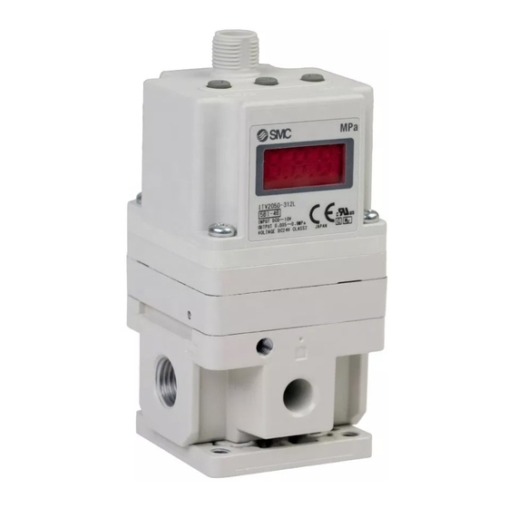
ITV1000, ITV2000, ITV3000 series
Contents
4-14-1,Sotokanda,Chiyoda-ku,Tokyo 101-0021 JAPAN
Tel:+81 3 5207 8249 Fax:+81 3 5298 5362
OPERATION MANUAL
E/P REGULATOR
MODEL NAME
Series
CONTENTS
-1-
P1
P2
P3-4
P5-6
P7-8
P9-10
P10
P11
P12
P12
Advertisement
Table of Contents

Related Manuals for SMC Networks ITV1000 Series


Summary of Contents for SMC Networks ITV1000 Series
-
Page 1: Table Of Contents
OPERATION MANUAL E/P REGULATOR MODEL NAME ITV1000, ITV2000, ITV3000 series Series CONTENTS Contents P1 Safety instructions P2 Handling precautions P3-4 Wiring method P5-6 Setting method P7-8 Manual adjustment of gain and sensitivity P9-10 Switch output P10 Key locking function ... -
Page 2: Safety Instructions
Safety instructions These safety instructions are intended to prevent a hazardous situation and/or equipment damage. These instructions indicate the level of potential hazard by labels of “CAUTION” “WARNING”, or “DANGER”. To ensure safety, be sure to observe ISO 4414, JIS B 8370 and other safety practices. ■Explanation of label Label Meaning of label △ Operator error could result in serious injury or loss of life. WARNING ! △ Operator error could result in injury or equipment damage. CAUTION ! △ WARNING ! ①The compatibility of pneumatic equipment is the responsibility of the person who designs the pneumatic system or decides its specifications. Since the products specified here are used in various operating conditions, their compatibility for the specific pneumatic system must be based on specifications or after analyses and/or tests to meet your specific requirements. The expected performance and safety assurance will be the responsibility of the person who has determined the compatibility of the system. This person should continuously review the suitability of all ... -
Page 3: Handling Precautions
Handling precautions △ CAUTION ! If power to this product is cut off due to a power failure, etc. when it is in a controlled state, residual pressure will be retained temporarily. Handle carefully when operating with output pressure released to the atmosphere, as air will continue to flow out. If supply pressure to this product is interrupted or shut off, while the power is still on, the internal solenoid valve will continue to operate and a humming noise may be generated. Since the life of the product may be shortened, shut off the power supply also ... - Page 4 △ CAUTION ! Take the following steps to avoid malfunction due to noise. 1) Install a line filter etc. to the AC power line to reduce / eliminate power supply noise. 2) Avoid malfunction due to noise by installing this product and its wiring away from strong electric fields, such as those of motors and power line, etc. 3) Be sure to implement protective measures against load surge for induction loads (solenoid valves, relays etc.). 4) Turn off the power supply before installing or removing the connector. Please note that the right angled cable connector does not rotate and is limited to ...
-
Page 5: Wiring Method
Wiring method △ CAUTION ! ① Proceed carefully, as incorrect wiring can cause damage. ② Use DC power supply with sufficient capacity and a low ripple. ③ Turn off the power supply to remove and insert the connector. ④ Never turn the right angled type connector as it is not designed to turn. 1 Brown Power supply 2 White Input signal 3 Blue GND(COMMON) 4 Black Monitor output 3:Blue 1:Brown 4:Black 2:White ... - Page 6 Wiring diagram(Monitor output) △ CAUTION ! When the monitor output is not being used, prevent it from touching the other wires as this can cause a malfunction. Analogue output・Voltage type Analogue output・Current (sink) type (ITV※0※※-※1) (ITV※0※※-※4) 1: 1: Brown Brown ○ 3: 3: Blue Blue ○ 2: 2: White Monitor output current White Monitor output voltage ...
-
Page 7: Setting Method
Setting method △ CAUTION ! ① If the incorrect key is pressed or incorrect information is displayed during setting, power must be shut off and the procedure started again. ② It is recommended that the settings are changed without supply pressure. The product operates immediately maximum and minimum pressures are set and the <SET> key is pressed. The minimum pressure is output when air is supplied to the inlet, even if the ③ input signal has not been entered. Preset input type(ITV※0※※-4) No Key operation LED Display ① Unlock keys (refer to P11) ② Press <SET> key ⇔ (displayed alternately) ③ Set P̲1 by using the △ and ▽ keys. Change the value by using △ and ▽ keys. ④ Press <SET> key ⇔ (displayed alternately) ⑤ ... - Page 8 Current・Voltage type(ITV※0※※-0、ITV※0※※-1、ITV※0※※-2、ITV※0※※-3) No Key operation LED Display ① Unlock keys (refer to P11) ② Press <SET> key ⇔ (displayed alternately) Set the minimum pressure by using the △ Change the value by using △ and ▽ keys. ③ and ▽ keys. *Adjusting range: Refer to figures below and note 1 to 4 ④ Press <SET> key ⇔ (displayed alternately) Set the maximum pressure by using the △ Change the value by using △ and ▽ keys. ⑤ and ▽ keys. *Adjusting range: Refer to figures below and note 1 to 4 ⑥ Go to no. ⑪ for monitor output: analogue output (voltage and current) type. ⑦ Press <SET> key ⇔ (displayed alternately) ⑧ Set the P̲1 by using the △ and ▽ keys.
-
Page 9: Manual Adjustment Of Gain And Sensitivity
Manual adjustment of gain and sensitivity Normal operation does not require the adjustment of gain and sensitivity. However, if adjustment is required to reduce the noise level, adjust gain and sensitivity until a more stable output pressure is reached. No Key operation LED Display ① Unlock keys (refer to P11) (current) pressure display ② Press ▽ key for 3 seconds or more. is displayed for approx. 2 seconds and ③ (current) pressure is displayed afterwards ④ Press <SET> key Current・Voltage input type Preset input type is displayed is displayed Press <SET> key Press <SET> key ⑤ is displayed is displayed Press <SET> key Press <SET> key Analogue output type Switch output type is displayed is displayed Press <SET> key Press <SET> key ... -
Page 10: Switch Output
Relation between setting of gain and response time Response time Quick Slow Setting of gain GL.9 GL.8 GL.7 GL.6 GL.5 GL.4 GL.3 GL.2 GL.1 GL.0 Relation between setting and sensitivity Sensitivity Sharp Dull Setting of sensitivity SL.0 SL.1 SL.2 Switch output The following operation types are available by setting P̲1 and P̲2. Note). This function is available for monitor output: switch output type (ITV※0※※-※2 and ITV※0※※-※3). ... -
Page 11: Key Locking Function
Key locking function △ CAUTION ! The keys are locked after turning the power on and can not be operated. Unlocking the keys No Key operation LED Display ① (current) pressure is displayed ② Press ▽ key for 2 seconds or more. is displayed ③ flashes on the display ④ Press <SET> key is displayed for approx. 1 ⑤ second ⑥ Key lock is released (current) pressure is displayed ※④ Press △ key to cancel. Locking the keys No Key operation ... -
Page 12: Reset Function
Reset function Reset method No Key operation LED Display ① Unlock keys (refer to P11) Press the △ and ▽ keys ② simultaneously for 3 seconds or (Current) pressure is displayed more. ③ is displayed for approx. 1 second ④ The setting is reset Reset content Item Reset content Application model ... -
Page 13: Url Http://Www.smcworld.com
取扱説明書 / OPERATION MANUAL 電空レギュレータ E/P REGULATOR 機種名称 / MODEL NAME ITV1000, ITV2000, ITV3000 series 型式 / Series <デジタル入力タイプ> 目 次 目次 P1 安全にご使用いただくために P2 取扱い上の注意 P3 仕様 P4 配線方法 P5 圧力設定 ... - Page 14 安全にご使用いただくために ここに示した注意事項は、製品を安全に正しくお使いいただき、あなたや他の人々へ の危害や損害を未然に防止するためのものです。これらの事項は、危害や損害の大き さと切迫の程度を明示するために、「注意」「警告」「危険」の三つに区分されてい ます。いずれも安全に関する重要な内容です IS0 4414、JIS B 8370、およびその他 の安全規則に加えて、必ずお守りください。 ■表示の説明 表示 表示の意味 取扱いを誤った時に、人が死亡もしくは重傷を負う可能性が想定 △ 警告 ! されるもの。 取扱いを誤った時に、人が損害を負う危険が想定される時、およ △ 注意 ! び物的損害のみの発生が想定されるもの。 △ 警告 ! ① 空気圧機器の適合性の決定は、空気圧システムの設計者または仕様を決定する人 が判断してください。 本製品のシステムへの適合性の決定は、空気圧システムの設計者または仕様を決 定する人が、必要に応じて分析やテストを行ってから決定してください。このシ ステムの所期の性能、安全性の保証は、システムの適合性を決定した人の責任に なります。これからも最新の製品カタログや資料により、仕様の全ての内容を検 討し、機器の故障の可能性についての状況を考慮してシステムを構成してくださ い。 ② 十分な知識と経験を持った人が取扱ってください。 圧縮空気は、取扱いを誤ると危険です。空気圧機器を使用した機械・装置の組立て や操作、メンテナンスなどは、十分な知識と経験を持った人が行ってください。 ③...
- Page 15 取扱い上の注意 △ 注意 ! 本製品は、 制御状態において停電等により電源が 断たれた場合、 2次側の出力は一時的に保持され ます。また、2次側の出力を大気開放状態で使用 している場合には、 そのまま流出し続けますので 取り扱いに注意してください。 本製品に通電したまま供給圧力を断ちますと、 内 蔵の電磁弁が動作し続け、 うなり音を発生する場 合があります。 内蔵の電磁弁の寿命に大きく影響 することがありますので、 供給圧力を遮断する場 合には、 本製品の電源を必ず切るようにしてくだ さい。 本製品は、当社工場出荷時に、各仕様にあわせて 調整済みとなっております。不用意な分解、各部 の取り外しは故障の原因となりますので、 避けて ください。 ノイズによる誤動作を避けるため、 次の対策を行 ってください。 1) A C電源ラインにラインフィルタなどを 入れ、電源ノイズを除去して使用してくだ さい。 2) ...
- Page 16 仕様 供給圧力 注1) (最大設定圧力+0.1MPa)〜1MPa 0.005〜0.1MPa 設定圧力 0.005〜0.5MPa 0.005〜0.9MPa 電源電圧 DC24V±10% 消費電流 MAX.120mA 入力信号 ディジタル10bit(パラレル入力) 入力インピーダンス 約4.7kΩ リニアリティ ±1%F.S.以下 ヒステリシス 0.5%F.S.以下 繰返し性 ±0.5%F.S.以下 感度 0.2%F.S.以下 使用温度 0〜50℃(結露無きこと) 保護構造 IP65相当 約300g(付属品無)ITV1000 質量 約400g(付属品無)ITV2000 約670g(付属品無)ITV3000 注1)出力圧力0.1MPa仕様は最大0.2MPaまで。 ...
- Page 17 配線方法 △ 注意 ! ① 配線を誤りますと破損する場合がありますので注意してください。 ② DC電源は十分な容量でリップルの少ないものをご使用ください。 ③ 電源を切ってからコネクタを抜き差ししてください。 表1 ケーブル信号線割り当て 信号線色 信号名 ピンク−黒帯2 供給電源(DC24V) 緑−黒帯2 供給電源(DC0V) 青 信号コモン(極性なし) 青−黒帯2 MSB 10ビット 灰−黒帯1 9ビット オレンジ−黒帯1 8ビット 緑−黒帯1 ...
- Page 18 圧力設定 例)ITV2030(0.5MPa仕様)で、設定圧力を0.3MPaにする場合。 (0.3MPa/0.5MPa)×1023=614(DEC) 10進数“614”を2進数に変換すると、“10 0110 0110” 得られた値 信号線 10ビット 9ビット 8ビット 7ビット 6ビット 5ビット 4ビット 3ビット 2ビット 1ビット 入力 コモンと各信号線間に12〜24Vを印加することにより、 “入力ON”の状態となり ます。 コモンの極性はありません。 エラー表示機能 エラー LED エラー内容 対処方法 番号 表示 EEPROMの読み込み、 書き 弊社までご一報ください。 ...
- Page 19 文書No. ITV2-OM00108-C 製 品 名 称 電空レギュレータ (16 点プリセット入力タイプ) 型式 / シリーズ / 品番 ITV1000/2000/3000/2090-52* シリーズ (スイッチ出力:NPN 出力) ITV1000/2000/3000/2090-53* シリーズ (スイッチ出力:PNP 出力) ● 取扱説明書は、よく読んで内容をよく理解した上で製品を取付け、ご使用ください。 ● 特に安全に関する記述は、注意深くお読みください。 ...
- Page 20 目次 目次 安全上のご注意 取扱い上のご注意 配線方法 入力信号とプリセット圧力の対応表 設定方法 キーロック機能 最小圧力・最大圧力・プリセット圧力の設定 オートメモリ機能 スイッチ出力(自己診断モード) エラー表示機能 詳細設定モード ゲイン調整機能 感度調整機能 ゼロクリア機能 初期化 LED 表示 - 1 -...
- Page 21 電空レギュレータ 安全上のご注意 ここに示した注意事項は、製品を安全に正しくお使いいただき、あなたや他の人々への危害や損害を未然に防 止するためのものです。これらの事項は、危害や損害の大きさと切迫の程度を明示するために、「注意」 「警告」 「危険」の三つに区分されています。いずれも安全に関する重要な内容ですから、国際規格(ISO / IEC)、日本工業 規格(JIS) およびその他の安全法規 に加えて、必ず守ってください。 *1) ISO 4414: Pneumatic fluid power -- General rules relating to systems. ISO 4413: Hydraulic fluid power -- General rules relating to systems. IEC 60204-1: Safety of machinery -- Electrical equipment of machines. (Part 1: General requirements) ISO 10218-1992:Manipulating industrial robots-Safety. JIS B 8370: 空気圧システム通則 ...
- Page 22 電空レギュレータ 安全上のご注意 注意 当社の製品は、製造業向けとして提供しています。 ここに掲載されている当社の製品は、主に製造業を目的とした平和利用向けに提供しています。 製造業以外でのご使用を検討される場合には、当社にご相談いただき必要に応じて仕様書の取り交わし、契約 などを行ってください。 ご不明な点などがありましたら、当社最寄りの営業拠点にお問い合わせ願います。 保証および免責事項/適合用途の条件 製品をご使用いただく際、以下の「保証および免責事項」、「適合用途の条件」を適用させていただきます。 下記内容をご確認いただき、ご承諾のうえ当社製品をご使用ください。 『保証および免責事項』 ①当社製品についての保証期間は、使用開始から 1 年以内、もしくは納入後 1.5 年以内、 いずれか早期に到達 *3) する期間です。 また製品には、耐久回数、走行距離、交換部品などを定めているものがありますので、当社最寄りの営業拠 点にご確認ください。 ②保証期間中において当社の責による故障や損傷が明らかになった場合には、代替品または必要な交換部品 の提供を行わせていただきます。 なお、ここでの保証は、当社製品単体の保証を意味するもので、当社製品の故障により誘発される損害は、 保証の対象範囲から除外します。 ③その他製品個別の保証および免責事項も参照、理解の上、ご使用ください。 ...
- Page 23 取扱い上の注意 △ 注意 ! 本製品は、制御状態において停電等により電源が断 たれた場合、2 次側の出力がそのまま流出し続けま すので取り扱いに注意してください。 本製品に通電したまま供給圧力を断ちますと、内蔵 の電磁弁が動作し続け、うなり音を発生する場合が あります。 内蔵の電磁弁の寿命に大きく影響することがあり ますので、供給圧力を遮断する場合には、本製品の 電源を必ず切るようにしてください。 オプションの電源ケーブルコネクタは 4 芯線です。 モニタ出力(スイッチ出力)を使用されない場合は 誤動作の原因となりますので他の線などと接触し ないように処理してください。 本製品は、当社工場出荷時に、各仕様にあわせて調 整済みとなっております。 不用意な分解、各部の取り外しは故障の原因となり ますので、避けてください。 - 4 -...
- Page 24 △ 注意 ! ノイズによる誤動作を避けるため、次の対策を行っ てください。 1. AC 電源ラインにラインフィルタなどを入れ、 電 源ノイズを除去して使用してください。 2. モーターや動力線などの強磁界と本製品及び本 製品への配線を出来るだけ離し、ノイズの影響を 受けないように設置してください。 3. 誘導負荷(電磁弁、リレーなど)には必ず負荷サ ージ対策を行ってください。 4. 電源のチャタリングによる影響を受けないよう に、電源を切ってからコネクタを抜き差ししてく ださい。 ライトアングル型ケーブルコネクタは回転しません ので絶対に回さないでください。 - 5 -...
- Page 25 配線方法 △ 注意 ! ① 配線を誤りますと破損する場合がありますので注意してください。 ② DC電源は十分な容量でリップルの少ないものをご使用ください。 ③ 電源を切ってからコネクタを抜き差ししてください。 ④ ライトアングル型のケーブルコネクタは回転しませんので絶対にまわさない でください。 ⑤ モニタ出力を使用されない場合は誤動作の原因となりますので他の線などと 接触しないように処理してください。 電源コネクタ 1 茶 電源電圧 Vcc 2 白 NC 3 青 GND 4 黒 モニタ出力 信号コネクタ 1 茶 入力信号1 2 白 入力信号2 3 ...
- Page 26 配線図(入力信号) S1 1:茶 2:白 S2 3:青 S3 S4 4:黒 供給電源 5:灰 供給電源 DC24V±10% ※コモン極性なし 供給電源はプラスマイナスどちら向きでも接続できます。 入力信号とプリセット圧力の対応表 プリセット圧力 入力信号4 入力信号3 入力信号2 入力信号1 黒:S4 青:S3 白:S2 茶:S1 P01 OFF ...
- Page 27 設定方法 △ 注意 ! ① 各値を設定している時に、キー操作を間違った場合、またはLED表示が異 なって表示された場合、一度電源を切って、もう一度最初から設定してくだ さい。 ② プリセット圧力の数値設定を終了し、Sキーを押すと、すぐに動作を開始し ますので、十分注意して行ってください。供給圧力なしでの操作を推奨いた します。 ③ 信号が入力されていなくても、1次側に圧力が供給されている場合、P01 に設 定された圧力を二次側に出力しますので、十分に注意して行ってください。 ④ 各種設定・機能に関して、操作を行うことにより、本製品から出力される圧 力や動作の状態が変化します。各操作の内容、取り付け装置への影響を把握 した上で、十分な知識と経験を持った人が行ってください。 各種設定の流れ 電源投入 P9 参照 キーロック解除 P9 参照 キーロック P10 参照 P10 参照 ...
- Page 28 キーロック機能 △ 注意 ! 電源投入直後はキーロック状態になっており、キー操作が出来ません。 キーロック解除方法 No キー操作 LED表示 ① 現在圧力を表示 ② ▽キーを 2 秒以上押し続ける の文字が点灯 ③ の文字が点滅 ④ Sキーを押す ⑤ を約 1 秒表示 ⑥ キーロックが解除される 現在圧力を表示 ※④で△キーを押すとキャンセルされます。 キーロック方法 No キー操作 LED表示 ① 現在圧力を表示 ...
- Page 29 最小圧力・最大圧力・プリセット圧力の設定 No キー操作 LED表示 ① キーロックを解除(P9 参照) ② Sキーを押す △、 ▽キーを押し、 最小圧力を変更 ⇔ (左右交互に表示) ③ (注1) ※調整範囲:注2〜3参照 ④ Sキーを押す (注4) △、 ▽キーを押し、 最大圧力を変更 ⇔ (左右交互に表示) ⑤ (注1) ※調整範囲:注2〜3参照 ⑥ Sキーを押す (注4) ⑦ △、▽キーを押し、P01 を設定 ⇔...
- Page 30 スイッチ出力(自己診断モード) 設定圧力の±5%F.S.に到達した時にスイッチ出力が ON となります。 入力信号 電空レギュレータの出力圧力 ON スイッチ出力 OFF エラー表示機能 エラー LED エラー内容 処置方法 名称 表示 電源を再投入しても復帰し EEPROMの読み込み、 ない場合は、 「初期化(P16 書き込みにエラーが発生し 参照) 」 を実施してください。 システム た場合 復帰しない場合は、 当社での エラー 調査が必要になります。 電源を再投入しても復帰し メモリーの読み込み、書き ない場合は、...
- Page 31 詳細設定モード No キー操作およびLED表示 ① キーロックを解除(P9 参照) ② Sキーを 2 秒以上押し続ける ⇔ (左右交互に表示) △キー ↑ Sキーを押す ↓ ▽キー 「ゲイン調整」へ(P12) ...
- Page 32 ⑥ Sキーを押す ⇔ (交互に表示) Sキーを 2 秒以上押し続け、詳細設定モードから抜ける ⑦ (△、▽キーでメニュー選択することで、別項目の設定に移動できます。 ) ⑧ キーロックを実施(P9 参照) ゲインの設定と応答性の関係 応答性 遅い 速い ゲ イ ン 〜 の設定 ※出荷時の初期値は、 「 」です。 感度調整機能 通常のご使用方法では、 出荷時の状態のままご使用いただき、 特に感度調整する必 要性はありません。 感度を変更することにより、 設定圧力近傍での圧力の補正動作が変化します。 感度 を鋭くすると、ハンチングが発生する場合があります。また、感度を鈍くすると、...
- Page 33 ゼロクリア機能 ゼロクリアを実施することにより、表示をゼロに再セットすることが出来ます。 配管内に残圧がある状態でゼロクリアを実施すると、 その圧力をゼロとしてしまい ます。ゼロクリアの操作は、供給圧力を遮断し、二次側の配管を外した状態で実施 してください。 No キー操作 LED表示 ① キーロックを解除(P9 参照) ② Sキーを 2 秒以上押し続け、詳細設定モードに入る。 ③ △、▽キーで、 「F03」にする。 ⇔ (交互に表示) ④ Sキーを押す。 (点滅) △、▽キーを同時長押しする。 ⑤ (点灯) (Sキーを押すと③の状態へ) ⑤ の同時長押し 3 秒経過でゼロクリア実 ⑥ 行 (1秒表示) (3 秒未満で離した場合は、④の状態へ)...
- Page 34 ⑤の同時長押し 5 秒経過で初期化実行 ⑥ 1秒間消灯 (5 秒未満で離した場合は、④の状態へ) ⑦ 電源投入直後の状態へ復帰します。 (キーロック状態) LED 表示 LED 圧力表示の範囲は、製品の圧力レンジや表示単位によって異なり、それぞれ下 表の通りです。 表示単位 ITV※01※ ITV※03※ ITV※05※ ITV209※ MPa 。020〜.120 。100〜.600 。180〜.A80 - Kgf/cm 0。20〜.120 1。00〜6.00 1。80〜A.80 - bar 0。20〜.120 1。00〜6.00 1。80〜A.80 - PSI 3。0〜18.0 14。0〜84.0 -26〜156 ...
Need help?
Do you have a question about the ITV1000 Series and is the answer not in the manual?
Questions and answers