Table of Contents
Advertisement
Quick Links
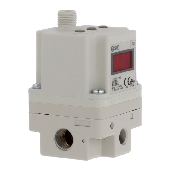
ITV1-TFK02-A
Installation and Maintenance Manual
Electro-Pneumatic Regulator with negative
terminal of power line separated from signal
line.
Series ITV1000-DIK00137
1 Safety Instructions
This manual contains essential information for the protection of users and
others from possible injury and/or equipment damage.
• Read this manual before using the product, to ensure correct handling,
and read the manuals of related apparatus before use.
• Keep this manual in a safe place for future reference.
• These instructions indicate the level of potential hazard by label of
"Caution", "Warning" or "Danger", followed by important safety
information which must be carefully followed.
• To ensure safety of personnel and equipment the safety instructions in
this manual and the product catalogue must be observed, along with
other relevant safety practices.
Indicates a hazard with a low level of risk, which if
Caution
not avoided, could result in minor or moderate injury.
Indicates a hazard with a medium level of risk, which
Warning
if not avoided, could result in death or serious injury.
Indicates a hazard with a high level of risk, which if
Danger
not avoided, will result in death or serious injury.
• Electromagnetic compatibility:
This product is class A equipment intended for use in an industrial
environment.
There
may
be
potential
difficulties
in
electromagnetic compatibility in other environments due to conducted as
well as radiated disturbances.
• The compatibility of pneumatic equipment is the responsibility of
the person who designs the pneumatic system or decides its
specifications.
Since the products specified here can be used in various operating
conditions, their compatibility with the specific pneumatic system must
be based on specifications or after analysis and/or tests to meet specific
requirements.
• Only trained personnel should operate pneumatically operated
machinery and equipment.
Compressed air can be dangerous if an operator is unfamiliar with it.
Assembly, handling or repair of pneumatic systems should be performed
by trained and experienced personnel.
• Do not service machinery/equipment or attempt to remove
components until safety is confirmed.
• Inspection and maintenance of machinery/equipment should only be
performed after confirmation of safe locked-out control positions.
• When equipment is to be removed, confirm the safety process as
mentioned above. Switch off air and electrical supplies and exhaust all
residual compressed air in the system.
• Before machinery/equipment is re-started, ensure all safety measures
to prevent sudden movement of cylinders etc. (Supply air into the
system gradually to create back pressure, i.e. incorporate a soft-start
valve).
• Do not use this product outside of the specifications. Contact SMC
if it is to be used in any of the following conditions:
• Conditions and environments beyond the given specifications, or if the
product is to be used outdoors.
• Installations in conjunction with atomic energy, railway, air navigation,
vehicles, medical equipment, food and beverage, recreation equipment,
emergency stop circuits, press applications, or safety equipment.
• An application, which has the possibility of having negative effects on
people, property, or animals, requiring special safety analysis.
• Ensure that the air supply system is filtered to 5 microns.
2 Specifications
Model
ITV1010
ITV1030
Min. supply pressure
(Set pressure) + 0.1 MPa
Max. supply pressure
0.2 MPa
Set pressure range
0.005 ~ 0.1 MPa 0.005 ~ 0.5 MPa
Supply voltage
24 VDC±10%
Current consumption
Max. 120 mA
Note1
4-20 mADC
Input signal
Max. 250 Ω
Input impedance
Linearity
Max. ±1%F.S.
Hysteresis
Max. 0.5%F.S.
Repeatability
Max. ±0.5%F.S.
Sensitivity
Max. 0.2%F.S.
Temperature characteristics
Max. ±0.12%F.S./°C
Operating temperature
0~50°C (without condensation)
Accuracy
Pressure
MPa: 0.01, kgf/cm
display
Min. Unit
PSI: 0.1
Protection structure
Main unit: IP65, Cable connector: IP67
Table 1.
Note 1: Two wire 4 to 20 mADC control. Negative terminal of power line is separated
from that of signal line.
Note 2: 1 PSI is the minimum unit on ITV1050.
ensuring
3 Operation Principle
When the input signal increases the supply solenoid valve
the exhaust solenoid valve
turns off. Supply pressure is passed to the
pilot valve
through the supply solenoid valve. The pilot valve will open
the main valve allowing partial supply pressure to pass to the out port. The
pressure sensor
will provide output pressure feedback to the control
circuit
. The control circuit will balance the input signal and output
pressure to ensure that the output pressure remains proportional to the
input signal.
Supply pressure
S
upply solenoid valve
+
Input
Control circuit
signal
E
xhaust solenoid valve
–
Pressure sens r o
Fig. 1 - Control diagram
Pressure
display
Power supply
Control
circuit
Input signal
Supply solenoid
valve
EXH
SUP
Pilot valve
Fig. 2 - Schematic diagram
4 Wiring
ITV1050
Connect the cable to the connector on the main unit as shown in the
following diagram. Take precautions, as incorrect wiring will damage the
1.0 MPa
unit. Use a DC power supply capable of supplying the necessary power
0.005 ~ 0.9 MPa
requirements with minimal ripple.
Brown
Brown
White
Blue
Blue
White
Black
Black
Note
Blue
Main
unit
Black
±3%F.S
Brown
2
: 0.01, bar: 0.01,
Note 2
, kPa: 1
Blue
White
Black
Straight type connector
Fig. 5 – Connector types
5 Setting the Regulator
turns on and
When the 'set' key is operated minimum/maximum pressure will be present
at the outlet port. When primary pressure is applied to the regulator
minimum pressure will be present at the outlet port.
Down key
OUT
Pilot valve
Air supply
port
Fig. 6 - Key features of the ITV
• Release 'Key Lock 'as explained in section 'Function of Key-Lock'
Exhaust solenoid
• After releasing key lock, SET needs to be pressed again to get to F-1
valve
• To set minimum pressure (display shows F-1) use up/down keys and
Pilot EXH
press 'Set' key to 'Lock' setting.
Pressure
• To set maximum pressure (display shows F-2) use up/down keys and
sensor
press 'Set' key to 'Lock' setting.
Note 1: If the above sequence has been followed correctly, the settings will
complete automatically.
OUT
Note 2: If only setting minimum pressure, when pressure is 'Set', pressing
the set button once more will 'skip' to the next step..
6 Function of Key-Lock
The keys are locked after connecting power and cannot be operated. 'Loc'
is displayed when any keys are pushed.
• Key-Lock Release
• Push 'Down' key for longer than 2 seconds.
• Display will flash 'Loc' (locked).
• Push 'Set' key to unlock.
Fig. 3 - Connection details
Note: To cancel push 'Up' key.
Power supply +
Input signal +
Note: The right angle type
Power supply –
connector extends to
• Key-Lock• Push 'Up' key for longer than 2 seconds.
Input signal –
the left side (over the
• Display will flash 'unL' (unlocked).
• Push 'Set' key to lock.
supply port side)
Brown
Note: To cancel push 'Down' key.
White
7 Function of the 'Error' Display
If an abnormality is detected by the ITV the LED display will show 'Er'
followed by a code number. Isolate the power supply and ascertain the
problem and solve. Re-instate power supply after correcting fault. Error
Current signal type
codes are as shown in the table below.
Vs:
Power supply
24 VDC
A:
Input signal
4 to 20 mADC
No
1
2
3
Fig. 4 - Wiring diagram
4
8 Reset Function
• Push 'Up' and 'Down' keys (Fig 6) together for longer than 3 seconds.
• Display shows 'RES'.
• Release keys to reset minimum pressure and maximum pressure.
Right angle type connector
9 Installation & Maintenance
• If the electrical supply fails, settings are 'held' for a short period.
• If the air pressure fails with power 'on' the solenoid will 'flutter'. Turn off
the power.
• This product is pre-set at the factory and must not be dismantled by the
Electrical connector
user. Contact your local SMC office for advice.
• Ensure, when installing this product, that it is kept clear of power lines to
Up key
avoid noise interference.
• Ensure that load surge protection is fitted when inductive loads are
present (i.e. solenoid, relay etc.).
• Ensure precautions are in place if the product is used in a 'free flow
output 'condition. Air will continue to flow continuously.
Set key
• Do not use a lubricator on the input side of this product. If lubrication is
necessary, place the lubricator on the 'output' side.
• Ensure all air is exhausted from the product before maintenance.
• Length of connector cable shall be 10 m maximum.
LED display
Air out port
10 Contacts
AUSTRIA
BELGIUM
Gauge port
CZECH REP.
DENMARK
.
FINLAND
FRANCE
GERMANY
GREECE
HUNGARY
IRELAND
ITALY
URL :
http// www.smcworld.com (Global)
Specifications are subject to change without prior notice from the manufacturer.
© 2009 SMC Corporation All Rights Reserved.
Content
Display
Input signal is outside specification
Er 1
EEProm read/write error
Er 2
Memory read/write error
Er 3
Solenoid valve fault
Er 4
Table 2.
(43) 2262 62280
NETHERLANDS
(31) 20 531 8888
(32) 3 355 1464
NORWAY
(47) 67 12 90 20
(420) 541 424 611
POLAND
(48) 22 211 9600
(45) 7025 2900
PORTUGAL
(351) 21 471 1880
(358) 207 513513
SLOVAKIA
(421) 2 444 56725
(33) 1 6476 1000
SLOVENIA
(386) 73 885 412
(49) 6103 4020
SPAIN
(34) 945 184 100
(30) 210 271 7265
SWEDEN
(46) 8 603 1200
(36) 23 511 390
SWITZERLAND
(41) 52 396 3131
(353) 1 403 9000
UNITED KINGDOM
(44) 1908 563888
(39) 02 92711
http// www.smceu.com (Europe)
Advertisement
Table of Contents


Need help?
Do you have a question about the ITV1050 and is the answer not in the manual?
Questions and answers