SMC Networks ITV2000 series Installation And Maintenance Manual
Electro-pneumatic regulator
Hide thumbs
Also See for ITV2000 series:
- Easy programming manual (7 pages) ,
- Installation and maintenance manual (1 page) ,
- Manual (64 pages)
Advertisement
This manual should be read in conjunction with the current catalogue.
Safety Instructions
These safety instructions are intended to prevent a hazardous
situation and / or equipment damage. These instructions indicate the
level of potential hazard by label of "Caution" "Warning", or
"Danger". To ensure safety, be sure to observe ISO 4414
B 8370
and other safety practices.
(Note 2)
(Note1)
ISO 4414: Pneumatic fluid power-Recommendations for the
application of equipment to transmission and control systems.
m
(Note 2) JIS B 8370 : Pneumatic system axio
CAUTION : Operator error could result in injury or
equipment damage.
WARNING : Operator error could result in serious injury
or loss of life.
DANGER : In extreme conditions, there is a possible result
of serious injury or loss of life.
WARNING
1. The compatibility of pneumatic equipment is the responsibility of
the person who designs the pneumatic system or decides its
specifications.
Since the products specified here are used in various operating
conditions, their compatibility for the specific pneumatic system
must be based on specifications or after analysis and/or tests to
meet your specific requirements.
Specifications
Model
Max. Supply Pressure
0.2MPa (0.2kgf/cm
Setting Pressure Range
(0.05~ 1.0kgf/cm
Supply voltage
C urrent Type (Note 1)
In
put Signal
V oltage Type
C urrent Type
Input
I
mpedance
V oltage Type
Analog Output
(Note 2)
Output
Switch Output
Signal
Linearity
Hysteresis
R epeatability
Sensitivity
T emperature C haracteristics
Protection Structure
Accuracy
Display of
Pressure
Min. Unit
Ambient and fluid temperature
(
Note 1)
Two wire control, 4 to 20mADC and 0 to 20mADC are not available. Supply voltage of 12~ 15VDC or 24VDC is required.
(
Note 2)
Please make a selection of either Analog output or Switch output. Also select either NPN or PNP output when Switch output is selected.
(
Note 3)
1PSI is the minimum unit on ITV205□ or ITV305□
Operation Principal ITV2000(Fig 3)
When the input signal increases, the supply solenoid valve ① turns on and the exhaust solenoid valve ② turns off. Supply pressure is
passed to the pilot valve ③ through the supply solenoid valve. The pilot valve will open the main valve allowing partial supply pressure to
pass to the out port.
The pressure sensor ④ will provide output pressure feedback to the control circuit ⑤. The control circuit will balance the input signal and
output pressure to ensure that the output pressure remains proportional to the input signal.
Operation Principal ITV2000(Fig 4)
When the input signal increases, the vacuum solenoid valve ① turns ON, and the atmospheric pressure solenoid valve ② turns OFF.
Because of this, VAC and pilot chamber ③ are connected, the pressure in the pilot chamber ③ becomes negative and acts on the top of the
diaphragm. As a result, the vacuum pressure valve ⑤ which is linked to the diaphragm ④ opens, VAC and OUT are connected, and the set
pressure becomes negative.
This negative pressure feeds back to the control circuit ⑧ via the pressure sensor ⑦. Then, a correct operation works until a vacuum
pressure proportional to the input signal is reached, and a vacuum pressure is obtained which is always proportional to the input signal.
I
nstallation and Maintenance Manual
Series ITV2000,3000,2090
Electro-Pneumatic Regulator
For future reference, please keep this manual in a safe place
2. Only trained personnel should operate pneumatically operated
machinery and equipment.
Compressed air can be dangerous if an operator is unfamiliar with
it. Assembly, handling or repair of pneumatic systems should be
performed by trained and experienced operators
, JIS
(Note 1)
3. Do not service machinery / equipment or attempt to remove
component until safety is confirmed.
1) Inspection and maintenance of machinery / equipment should
only be performed after confirmation of safe locked-out control
positions.
2) When equipment is to be removed, confirm the safety process as
mentioned above. Switch off air and electrical supplies and
exhaust all residual compressed air in the system.
3) Before machinery / equipment is re-started, ensure all safety
measures to prevent sudden movement of cylinders etc. (Bleed
air into the system gradually to create back-pressure, i.e.
incorporate a soft-start valve.)
4. Contact SMC if the product is to be used in any of the following
conditions .
1) Conditions and environments beyond the given specifications, or if
product is used outdoors.
2) Installation on equipment in conjunction with atomic energy,
railway, air navigation, vehicles, medical equipment, food and
beverage, recreation equipment, emergency stop circuits, press
applications, or safety equipment.
3) An application which has the possibility of having negative effects
on people, property, or animals requiring special safety analysis.
CAUTION
Ensure that the air supply system is filtered to 5 micron.
ITV201□
ITV203□
ITV301□
ITV303□
2
)
1.0MPa (10.2kgf/cm
0.005~ 0.1MPa
0.005~ 0.5MPa
2
2
)
(0.05~ 5.1kgf/cm
)
Supply voltage
24VDC T ype : 0.12A or less
Supply voltage
12~ 15VDC Type : 0.18A or less
4~ 20mADC , 0~ 20mADC
0~ 5VDC , 0~ 10VDC
250Ω or less
APPRO X. 6.5kΩ
1~ 5VDC Load Impedance : more than 1kΩ
NPN Open C ollector T ype : 30V , 30mA
PNP Open C ollector Type : 30mA
± 1 % F .S . or less
0.5 % F .S . or less
± 0.5 % F .S . or less
0.2 % F .S . or less
± 0.12 % F .S . or less /℃
Main unit : Equivalent to IP65 C able connector : IP67
± 3%F .S .
MPa : 0.01, kgf/cm
2
: 0.01, bar : 0.01, PSI : 0.1 (note3), kPa : 1
0~ 50℃ (without condensation)
.
ITV205□
ITV209□
ITV305□
-101kPa
2
)
(-760mmHg)
0.005~ 0.9MPa
-1.3~ -80kPa
2
(0.05~ 9.2kgf/cm
)
(-10~ -600mmHg)
kPa : 1
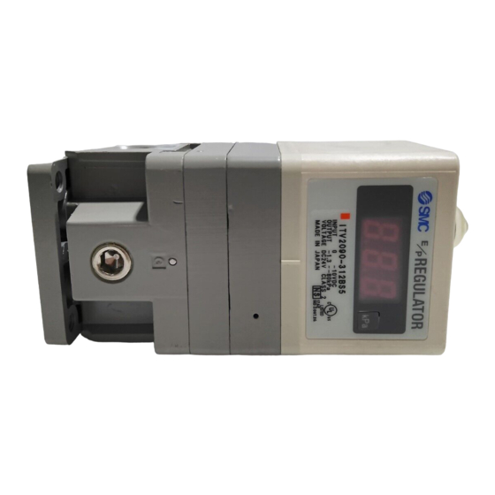
Electrical connector
Set Key
Down Key
Air supply port
Fig 1
Symbol
Fig 2
ITV2000,30000
Pressure
D isplay
P ow er supply
⑤C ontrol
circuit
Input signal
①S upply solenoid
valve
S U P
④Pilot valve
Fig 3
ITV2090
Fig 4
Up- Key
LED display
Air outlet port
Gauge port
②E xhaust
solenoid valve
④Pressure sensor
O U T
Advertisement
Table of Contents

Related Manuals for SMC Networks ITV2000 series


Summary of Contents for SMC Networks ITV2000 series
- Page 1 nstallation and Maintenance Manual Electrical connector Series ITV2000,3000,2090 Electro-Pneumatic Regulator Set Key Up- Key For future reference, please keep this manual in a safe place This manual should be read in conjunction with the current catalogue. Down Key Safety Instructions 2.
- Page 2 S u p p ly p re s s u re (V A C ) lock line char t CAUTION ① Supply solenoid valve Output 1. If the electrical supply fails, settings are ‘held’ for a short period. ( Vacuum sol.) pressure put signal ⑤...
Need help?
Do you have a question about the ITV2000 series and is the answer not in the manual?
Questions and answers