Table of Contents
Advertisement
Quick Links
Advertisement
Table of Contents

Related Manuals for Bosch ICP-SOL2-P


Summary of Contents for Bosch ICP-SOL2-P
-
Page 2: Table Of Contents
Swinger Shutdown Count For Siren 4.7.2 Swinger Shutdown Count For Dialer Zone Status Programming 4.8.1 STAY Mode 2 Automatically Bypass Zones 4.8.2 Reserved 4.8.3 Zone Status Reporting Options RF Programming 2014.06 | 02 | F01U298027 Quick Reference Guide Bosch Security Systems, Inc. -
Page 3: Dialer Options
4.15.9 Partitioning Options 1 4.15.10 Partitioning Options 2 4.16 Partition Allocations 4.16.1 Zone Area Assignment 4.16.2 Codepad Assignment 4.16.3 Reserved 4.16.4 User Code Area Assignment 4.17 Default Options Bosch Security Systems, Inc. Quick Reference Guide 2014.06 | 02 | F01U298027... -
Page 4: System Options
RF Repeater ID Numbers 4.22 Text Codepad Items 4.22.1 Home Message 4.22.2 Zone Names 4.22.3 User Names 4.22.4 Area Names Appendices Connections for EOL Resistors Wiring Diagram Component Overlay 2014.06 | 02 | F01U298027 Quick Reference Guide Bosch Security Systems, Inc. -
Page 5: Introduction
Introduction | en Introduction Thank you for choosing the ICP-SOL2-P/ICP-SOL3-P Control Panel for your installation. You will find this system extremely flexible, reliable, and easy to use. This Quick Reference Guide is supplied with the system to provide users with enough basic information to wire, configure, and program the system. -
Page 6: Programming
Enter the new data then [*] to save it. Enter [#] to go to the next location. When [Confirm to Save Parameter Changes?] display, press [#] to save parameter changes , exit menu programming and reset system. 2014.06 | 02 | F01U298027 Quick Reference Guide Bosch Security Systems, Inc. - Page 7 Alarm memory reset on disarm [497.4] STAY indicator for day alarm [496.4] Digit 3 for codepad duress alarm [498.2] Siren and strobe output in STAY [498.3] Speaker beep volume [491] Bosch Security Systems, Inc. Quick Reference Guide 2014.06 | 02 | F01U298027...
- Page 8 Swing shutdown Report swing shutdown count [380] Silent zone tamper alarm [498.4] Zone option Unseal RF zone that failed monitor [396.3] Bosch Smart Lockout enable [492.1] Zone pulse count handover enable [494.3] Handover delay in order [494.4] Codepad area [518]...
-
Page 9: Icon Lcd Codepad Programming
Step to next Location Step back one Location Program new data into Location [Data][*] (Data = 0 to 15) Jump to another Location [Location No.] [#] 2014.06 | 02 | F01U298027 Quick Reference Guide Bosch Security Systems, Inc. -
Page 10: Programming Option Bits
Copy IUI-SOL-ADAPTER data to the control panel memory Set up domestic dialing format Enable/disable the automatic stepping of locations during programming Display the software version number or control panel type Table 2.4: Installer’s Programming Commands Bosch Security Systems, Inc. Quick Reference Guide 2014.06 | 02 | F01U298027... -
Page 11: Operating Commands
[Code] + [3] + [#] √ √ Sequence Set STAY Mode 2 Zones [Code] + [4] + [#] √ √ Turn Outputs On/Off [Code] + [5] + [#] √ Bosch Security Systems, Inc. Quick Reference Guide 2014.06 | 02 | F01U298027... - Page 12 Modem Call (A-Link Plus) Long press [6] Latching Output (Reset) Long press [7] Display Codepad ID/Change Long press [8] Codepad Buzzer Tone Test Report Long press [9] Table 3.1: Operating Commands 2014.06 | 02 | F01U298027 Quick Reference Guide Bosch Security Systems, Inc.
-
Page 13: Add/Delete Rf Device (Wireless Zones)
Enter the WE800EV2 keyfob number (301 to 321) you want to add, followed by the [#] key. Only current keyfob number (1 to 16 ) displays on the ICON codepad. Bosch Security Systems, Inc. Quick Reference Guide 2014.06 | 02 | F01U298027... -
Page 14: Set First Test Report
Enter the Installer Code or Master Code followed by [3] and the [#] key. Press [2] followed by the [#] key. Enter the Call Forward Off sequence. Press the [#] key to exit. 2014.06 | 02 | F01U298027 Quick Reference Guide Bosch Security Systems, Inc. -
Page 15: Set Stay Mode 2 Zones
Enter the Installer Code or Master Code, followed by [8] and the [#] key. The last 256 events are displayed in reverse order (for example, most recent to least recent). Bosch Security Systems, Inc. Quick Reference Guide 2014.06 | 02 | F01U298027... -
Page 16: Fault Analysis Mode
IP Module 2 Fail Output and Output Expander Fail Codepad Fail 3 to 6 Codepad Fail Keyfob Low Battery 1 to 16 Keyfob 1 to 16 Low Battery Bosch Security Systems, Inc. Quick Reference Guide 2014.06 | 02 | F01U298027... - Page 17 RF device in question successfully transmits to the RF radio receiver. Press and hold the [5] key until two beeps sound. This displays the RF detection device reporting the RF sensor watch fault. 2014.06 | 02 | F01U298027 Quick Reference Guide Bosch Security Systems, Inc.
- Page 18 To determine which keyfob failed, press and hold the [8] key. Only keyfob 1 to 16 faults display on the codepad through zone indicator 1 to 16. Bosch Security Systems, Inc. Quick Reference Guide 2014.06 | 02 | F01U298027...
-
Page 19: Programming Parameters
0 = Not used 1 = Contact ID 4 = Domestic 6 = SIA Fast 7 = SIA Slow 8 = CSVIP 9 = Email Subscriber ID Number 0074 - 0079 Bosch Security Systems, Inc. Quick Reference Guide 2014.06 | 02 | F01U298027... -
Page 20: Dialing Format
15 = Telephone termination 4.1.9 Call Back Telephone Number Item Location Option Default Call Back Telephone 0159 - 0174 0 = 0 and 10 Number 15 = Telephone termination 2014.06 | 02 | F01U298027 Quick Reference Guide Bosch Security Systems, Inc. -
Page 21: Ring Count
1 = Arm/Disarm Reports only if alarmed 2 = STAY Mode Arm/Disarm Reports Enable 4 = Delay siren until transmission complete 8 = Extend handshake wait time from 30 to 60 sec. Bosch Security Systems, Inc. Quick Reference Guide 2014.06 | 02 | F01U298027... -
Page 22: A-Link Plus Options
User #04 0200 - 0203 0204 User #05 0205 - 0208 0209 User #06 0210 - 0213 0214 User #07 0215 - 0218 0219 User #08 0220 0224 2014.06 | 02 | F01U298027 Quick Reference Guide Bosch Security Systems, Inc. - Page 23 0640 User #32 0641 - 0644 0645 Authority Levels Description Arm/Disarm Arm Only Arm/Disarm and Arm/Disarm Reports Arm Only and Arm Reports Arm/Disarm and Code Required to Isolate Bosch Security Systems, Inc. Quick Reference Guide 2014.06 | 02 | F01U298027...
-
Page 24: Day Alarm Zones
Zone Options 1 0270 Zone Options 1 0326 Zone Options 2 0271 Zone Options 2 0327 Reserved 0272 Reserved 0328 Dialer Options 0273 Dialer Options 0329 Zone #02 Zone #10 2014.06 | 02 | F01U298027 Quick Reference Guide Bosch Security Systems, Inc. - Page 25 Zone Options 2 0299 Zone Options 2 0355 Reserved 0300 Reserved 0356 Dialer Options 0301 Dialer Options 0357 Zone #06 Zone #14 Zone Type 0302 Zone Type 0358 Bosch Security Systems, Inc. Quick Reference Guide 2014.06 | 02 | F01U298027...
- Page 26 Use the pulse count to program how many pulses (0 to 15) need to be registered within the pulse count time to activate an alarm. Zone Pulse Count Time 20 ms Loop Response Time 150 ms Loop Response Time 2014.06 | 02 | F01U298027 Quick Reference Guide Bosch Security Systems, Inc.
-
Page 27: Swinger Programming
Swinger Programming 4.7.1 Swinger Shutdown Count For Siren Item Location Option Default Swinger Shutdown Count 0379 1 – 15 = Number of times siren operates For Siren until lockout Bosch Security Systems, Inc. Quick Reference Guide 2014.06 | 02 | F01U298027... -
Page 28: Swinger Shutdown Count For Dialer
1 = Report to Receiver 1 2 = Report to Receiver 2 4 = Report to both Receiver 1 and Receiver 2 8 = Report to Receiver 2 only Receiver 1 fails 2014.06 | 02 | F01U298027 Quick Reference Guide Bosch Security Systems, Inc. -
Page 29: Rf Programming
4 = Unseal Zone That Fail Monitor 4.9.5 Reserved Item Location Option Default Reserved 0397 - 0400 4.10 Report Programming 4.10.1 Reserved Item Location Option Default Reserved 0401 - 0402 Bosch Security Systems, Inc. Quick Reference Guide 2014.06 | 02 | F01U298027... -
Page 30: Arm / Disarm Reporting Options
1 = Report to Receiver 1 2 = Report to Receiver 2 4 = Report to both Receiver 1 and Receiver 2 8 = Report to Receiver 2 only if Receiver 1 fails 2014.06 | 02 | F01U298027 Quick Reference Guide Bosch Security Systems, Inc. -
Page 31: Test Report Programming
0442 Event Code 0460 Event Code 0443 Event Code 0461 Polarity 0444 Polarity 0462 Time Base 0445 Time Base 0463 Time Base Multiplier 0446 Time Base Multiplier 0464 Bosch Security Systems, Inc. Quick Reference Guide 2014.06 | 02 | F01U298027... - Page 32 Time Base Multiplier 0675 Time Base Multiplier 0681 B308 Output 7 B308 Output 8 Event Code 0682 Event Code 0688 Event Code 0683 Event Code 0689 Polarity 0684 Polarity 0690 2014.06 | 02 | F01U298027 Quick Reference Guide Bosch Security Systems, Inc.
- Page 33 Mode 3 14 = Reserved 2 14 = Radio control output 2- not in AWAY 3 15 = Reserved Mode 2 15 = Communications fail after 3 attempts Bosch Security Systems, Inc. Quick Reference Guide 2014.06 | 02 | F01U298027...
- Page 34 OFF time. The OFF time is the time base x the multiplier. (For example, if you want the output to pulse 1 sec. ON and 5 sec. OFF, you would program time base as one and the multiplier as five.) 2014.06 | 02 | F01U298027 Quick Reference Guide Bosch Security Systems, Inc.
-
Page 35: Time Programming
Codepad Lockout Time Item Location Option Default Codepad Lockout Time 0478 0 = No lockout 1 – 15 = Lockout time 10 – 150 sec. (Increments of 10 sec.) Bosch Security Systems, Inc. Quick Reference Guide 2014.06 | 02 | F01U298027... -
Page 36: Siren Run Time
Minute of the day (tens digit) 0488 Minute of the day (units digit) 0489 4.14.13 Kiss-Off Wait Time Item Location Option Default Increments of 500 ms (500 ms to 8 0490 sec.) 2014.06 | 02 | F01U298027 Quick Reference Guide Bosch Security Systems, Inc. -
Page 37: Speaker Beep Volume
Item Location Option Default System Options 1 0492 1 = Bosch Security Systems smart lockout allowed 2 = Horn speaker monitor 4 = Strobe indication for radio arm/disarm 8 = Assign button 4 on transmitter to operate STAY Mode 1 4.15.2... -
Page 38: Consumer Options 1
Option Default Partitioning Options 1 0500 1 = First to Disarm/Last to Arm reporting 2 = Reserved 4 = Reset sirens from any area allowed 8 = Reserved 2014.06 | 02 | F01U298027 Quick Reference Guide Bosch Security Systems, Inc. -
Page 39: Partition Allocations
1 = Codepad address assigned to Area 1 3 = Codepad address assigned to both Area 1 and Area 4.16.3 Reserved Item Location Option Default Reserved 0522 - 0533 Bosch Security Systems, Inc. Quick Reference Guide 2014.06 | 02 | F01U298027... -
Page 40: User Code Area Assignment
1000 - 1099 CSVIP 1 User Name and Password 1100 - 1163 IP 2 + Port / Email 1200 - 1299 CSVIP 2 User Name and Password 1300 - 1363 2014.06 | 02 | F01U298027 Quick Reference Guide Bosch Security Systems, Inc. - Page 41 (Subscriber ID Number). In network configuration, select Network Module as Use and configure. Enter email receiver’s email address. Download programming data from A-Link Plus to the control panel. Bosch Security Systems, Inc. Quick Reference Guide 2014.06 | 02 | F01U298027...
-
Page 42: Rf User Code Id Numbers
1908 - 1909 RF Zone #10 1910 - 1917 1918 - 1919 RF Zone #11 1920 - 1927 1928 - 1929 RF Zone #12 1930 - 1937 1938 - 1939 2014.06 | 02 | F01U298027 Quick Reference Guide Bosch Security Systems, Inc. -
Page 43: Rf Repeater Id Numbers
Zone 10 Name 2752 - 2775 Zone 3 Name 2584 - 2607 Zone 11 Name 2776 - 2799 Zone 4 Name 2608 - 2631 Zone 12 Name 2800 - 2823 Bosch Security Systems, Inc. Quick Reference Guide 2014.06 | 02 | F01U298027... -
Page 44: User Names
User 16 Name 3280 - 3303 User 32 Name 3664 - 3687 4.22.4 Area Names Item Location Area 1 Name 3760 - 3783 Area 2 Name 3784 - 3807 2014.06 | 02 | F01U298027 Quick Reference Guide Bosch Security Systems, Inc. -
Page 45: Appendices
Single Zone input (Location 266 = 1k, 1k5, 2k2, 3k3, 3k9, 4k7, 5k6, 6k8, 10k, 12k, 22k) ZONE 1 Table 5.2: Connection 2 Double Zone with tamper (Location 266 = 14 (Split EOL3k3 / 6k8 with tamper 1k)) ZONE 5 (ICP-SOL2-P) ZONE 9 (ICP-SOL3-P) ZONE 1 (6K8 EOL) (3K3 EOL) Table 5.3: Connection 3... -
Page 46: Wiring Diagram
Max: 900mA Siren AUX : < 900mA Slow flash: Normal state On: Trouble state Off: Trouble state Smoke detector Bosch SDI2 Bus 1,2,3 < 900mA 12V 7Ah 18VAC@1.33A 230V ~50Hz 230mA Fuse 1 A Figure 5.1: Wiring Diagram 2014.06 | 02 | F01U298027 Quick Reference Guide Bosch Security Systems, Inc. -
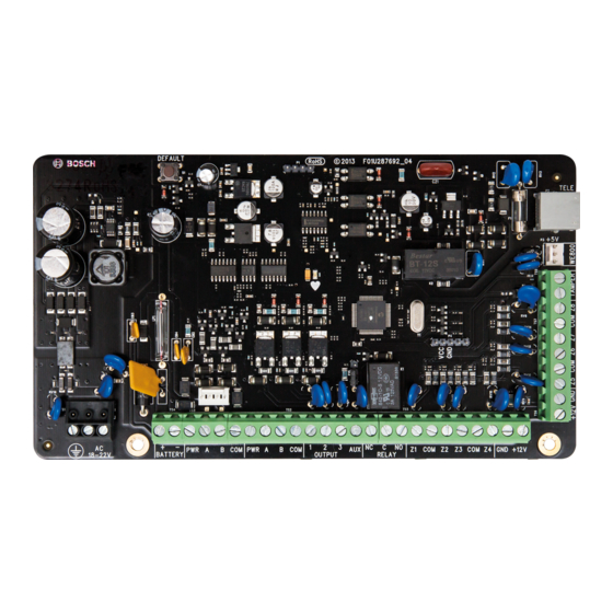
Page 47: Component Overlay
Control Panel Appendices | en Component Overlay Figure 5.2: Component Overlay Bosch Security Systems, Inc. Quick Reference Guide 2014.06 | 02 | F01U298027... - Page 48 6 – Zone 1-4 termination strip 13 – LED indicator ( Zone 1 - 4 and Zone 5 - 8 for ICP-SOL2-P; Zone 1 – 4 and Zone 9 – 12 for ICP-SOL3-P ) 7 – Output termination strip 14 –...
- Page 52 Bosch Security Systems, Inc. 130 Perinton Parkway Fairport, NY 14450 www.boschsecurity.com.au © Bosch Security Systems, Inc., 2014...
Need help?
Do you have a question about the ICP-SOL2-P and is the answer not in the manual?
Questions and answers