Advertisement
Quick Links
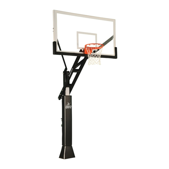
-- CVAC66 --
(THE TITAN CVX2 OUTDOOR ADJUSTABLE w/ ACRYLIC)
Installation Instructions
!
!
WARNING
FAILURE TO COMPLY WITH ANY OF
T H E W A R N I N G S I N T H E S E
INSTRUCTI ONS MAY RESUL T IN
S E R I O U S P E R S O N A L I N J U R Y .
FAILURE TO COMPLY MAY ALSO
RESULT I PROPERTY DAMAGE. PLEASE
HEED ALL WARNINGS AND CAUTIONS
T O E N S U R E Y O U R S A F E T Y .
DO NOT ATTEMPT TO ASSEMBLE THIS
S Y S T EM W I TH OU T C A R EF U L L Y
READING AND F OLL OWING ALL
I N S T R U C T I O N S B E G I N B Y
I D E N T I F Y I N G A N D T A K I N G
INVENTORY OF ALL PARTS USING THE
P A R T S L I S T P R O V I D E D .
Call Jaypro Sports Equipment at 1-800-243-0533
during regular business hours for technical support.
www.jaypro.com
Keep this instruction manual in case you have to contact the manufacturer for replacement parts.
Rev: -
[Type text]
Page 1 of 14
Advertisement

Subscribe to Our Youtube Channel
Related Manuals for Jaypro Sports CVAC66


Summary of Contents for Jaypro Sports CVAC66
- Page 1 I D E N T I F Y I N G A N D T A K I N G INVENTORY OF ALL PARTS USING THE P A R T S L I S T P R O V I D E D . Call Jaypro Sports Equipment at 1-800-243-0533 during regular business hours for technical support. www.jaypro.com Keep this instruction manual in case you have to contact the manufacturer for replacement parts.
- Page 2 TOOLS AND MATERIALS REQUIRED FOR ASSEMBLY (Not Included) 1) 2 Adjustable Wrenches 9) Shovel 2) Socket Set 10) Concrete 1/2 yard or 14- 3) 9/16” Wrench 16 Bags, (80 lbs. bags) 4) 3/4" Wrench 11) Philips Head Screwdriver 5) 15/16” Wrench 12) 2 Ladders (min.) or Crane 13) Carpenter’s Level 6) 1/2"...
- Page 3 Rev: - [Type text] Page 3 of 14...
- Page 4 Spacer Kit: Attached the backboard mounting bracket (N) to the spacer backboard (S1) as shown, with 3/8” x 1 1/2” hex bolt (S2), lock washer 3/8” (S3) and washer 3/8” (S4). NOTE: spacer is only for 42” x 72" rectangular acrylic backboard (ACRB-72) only, discarded the other instructions.
- Page 5 48” REF 58” REF 21” INSTALLATION TIP / REFERENCE OVERALL VIEW Rev: - [Type text] Page 5 of 14...
- Page 6 Footing: NOTE: Before digging, call to locate any buried utility lines. a. Dig a hole 48" deep x 21" across. The edge of the hole should be flush with the edge of the playing surface. If you live in an area where heavy frost can occur, it may pose a problem, consult your local building inspector to determine the appropriate hole depth.
- Page 7 Step 1: Slide a 18mm thick washer (U3) over each of the J-Bolts (U2) as shown in FIGURE 1A. b. Remove the padding from main post (A). Place he main post (A) over the J-Bolts. Slide a 18mm thick washer (U3), a Lock washer 18mm (U6) and thread a 18mm hex nut (U4) to each J-Bolt. Tighten the nuts only a few turns onto the J-Bolts as shown in FIGURE 1B.
- Page 8 Step 2: Slide the main extension arm (F) over the top of the main post (A) and attach to the lower pivot tube with a M18x320mm Hex Bolt (#5), two M18 flat washer (#11), two nylon washers M18 (#1) and one lock nut M18 (#14). NOTE: Make sure nylon washer located between main extension arm (F) and post (A).
- Page 9 Step 3: Connect actuator to main extension arm. Place the upper bracket of actuator (B) between the last set of welded tubes on the main extension arm (F), attach the two parts using hex bolt M18x320mm (#5), two flat washers M18 (#11), on lock nut (#14). b.
- Page 10 Step 4: Slide steel sleeve (J) thru both tubes welded at the top end of spring-assist cartridge (C). Place the top of spring-assist between main extension (F), align the steel sleeve (J) with the second set of welded tubes on the main extension arm (F), place the stainless-steel rim height indicator (K) beside the spring-assist cartridge (C).
- Page 11 Step 5: Attached the two upper extension arms (G) to main post (A) with one hex bolt M16x295mm (#6), two flat washers M16 (#12), two nylon washers M16 (#2) and one lock nut M16 (#15). NOTE: The nylon washers go between upper extension arm and main post. Do not tighten at this time.
- Page 12 Step 6: b. Remove the screws on rim springs box cover, open the spring box. (rim spring box may not be factory-assembled.) c. Mount the rim to the mounting bracket on backboard (H) using the hardware supplied in rim box (carriage bolt M10x110mm Long one).
- Page 13 Step 7: Crank the main extension arm as low as possible. Attached the backboard mounting bracket (n) to the main extension arm (F) by using a hex bolt M16x320mm (#7), two M16 flat washers (#12), two nylon washers (#2) and one lock nut M16 (#15).
- Page 14 Step 8: After everything is square, make sure all nuts on the system have been tightened. NOTE: Do not over tighten the nuts, make sure the unit can be adjusted up and down. b. To apply the rim height sticker (in the manual pack), first use a tape measure to crank rim up to exactly 10’...
Need help?
Do you have a question about the CVAC66 and is the answer not in the manual?
Questions and answers