
Related Manuals for Xylem ProSwap 610224-01


Summary of Contents for Xylem ProSwap 610224-01
- Page 1 USER MANUAL ITEM# 610224-01 REVISION A ProSwap Logger User Manual 1-PORT TEMPERATURE/DEPTH SONDE...
- Page 2 The information contained in this manual is subject to change without notice. Effort has been made to make the information in this manual complete, accurate, and current. The manufacturer shall not be held responsible for errors or omissions in this manual. Consult YSI.com for the most up-to-date version of this manual.
-
Page 3: Table Of Contents
TABLE OF CONTENTS 5. Kor Software 1. Introduction System Requirements ProSwap Logger Overview Software and Driver Installation ProSwap Logger Contents Connection to Kor Software ProSwap Logger Power Supply Kor Software Home Screen File Menu 2. Setup Calibration Menu Sensor Installation and Removal ProDIGITAL Handheld Menu Sensor Guard Installation Deployment Menu... -
Page 4: Introduction
Section 1 Introduction This section will cover the ProSwap Logger specifications, sonde contents, power supply, and introduce some relevant accessories. -
Page 5: Proswap Logger Overview
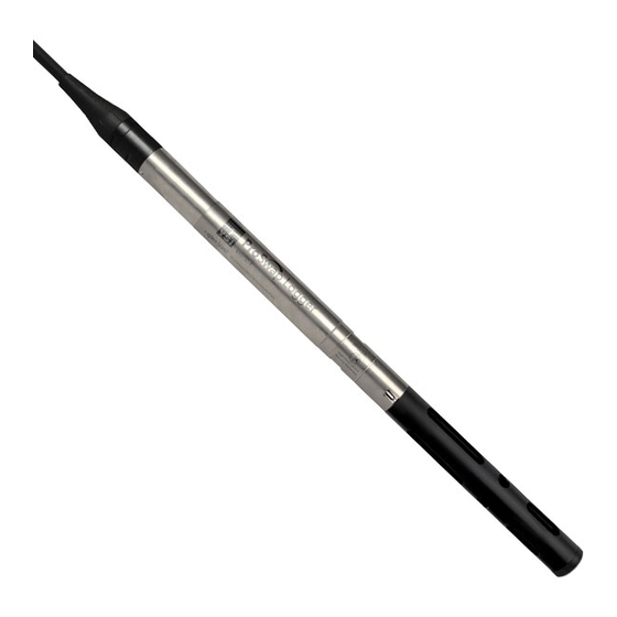
ProSwap Logger Overview The ProSwap Logger is a multiparameter instrument that collects water quality data. The sonde collects the data with a single user- replaceable sensor, plus an integral temperature sensor and pressure transducer. Each sensor measures its parameter via a variety of electrochemical, optical, or physical detection methods. - Page 6 ProSwap Logger Cable Battery Compartment Cable Connector Vent Tube Depth Sensor Thermistor Sensor Port Probe Guard Sensor...
-
Page 7: Proswap Logger Contents
ProSwap Logger Contents Inspect the outside of the shipping container(s) for damage. If you see any damage, contact the shipping carrier immediately. Carefully remove the equipment from the shipping box and verify that all contents are present. Contents: • ProSwap Logger with Integrated Cable •... -
Page 8: Proswap Logger Power Supply
ProSwap Logger Power Supply There are two different versions of the ProSwap Logger – one with an internal, rechargeable lithium ion battery and one without. Internal Battery Version Models: • 610150-XX • 610151-XX • 610152-XX This version includes a built-in, rechargeable lithium ion battery. This battery, fully charged, will last at least 90 days at a 15 minute log interval no matter which ProDSS Sensor is installed and may last longer depending on the sensor type. -
Page 9: Setup
Section 2 Setup This section will cover the setup and operation of the ProSwap Logger using a ProDIGITAL Handheld (ProSwap and ProDSS). To prepare the sonde for operation, you will need to: • Install sensor on the bulkhead or plug the port •... -
Page 10: Sensor Installation And Removal
ProDSS Sensor Installation and Removal The ProSwap Logger includes built-in temperature and depth sensors in addition to a single port. The port will allow any ProDSS smart sensor to be connected. NOTICE: The sensor connector and bulkhead port are not wet-mateable. Make sure that the sensor connector and bulkhead port are clean and dry before sensor installation. - Page 11 Sensor Installation To use the ProSwap Logger with a ProDSS Sensor, proceed with the following instructions: Remove the port cover shipped with the cable. Apply a thin coat of lubricant to the sensor o-rings. Carefully align the sensor and bulkhead connectors by inserting the sensor into the port then gently rotating the sensor until the connectors align.
-
Page 12: Sensor Guard Installation
Sensor Guard Installation A sensor guard must be installed in order to protect the ProDSS sensor being used with the ProSwap Logger. Damage resulting from use without a sensor guard is not covered under warranty. Carefully slide the sensor guard over the bulkhead and attached sensors/port plugs. Push the sensor guard toward the bulkhead until the sensor guard threads align with the bulkhead threads. -
Page 13: Connection To Handheld
Connection to ProDIGITAL Handheld The ProSwap Logger is designed to interface with the ProSwap Handheld and ProDSS Handheld meters via the MS-8 connector. NOTICE: Be sure that the handheld is updated to the latest firmware (version 1.3.8 or newer). Align the keys on the cable connector with the slots on the handheld connector. Push together firmly, and then twist the outer ring clockwise until it locks into place. -
Page 14: Connection To Kor Software
Connection to Kor Software The ProSwap Logger can be connected to a PC running Kor Software via a USB adapter. A ProDIGITAL USB adapter is sold separately. Alternatively, the software communication may be established through the handheld’s USB port. Download the Kor installer from YSI.com and extract the .zip file, or connect the included USB drive to your PC. Right click on Start.exe and select “Run as administrator”. - Page 15 Section 3 Handheld Operation This section will cover operation of the ProSwap Logger using a handheld meter. Interfacing with the ProSwap Logger can be accomplished using a ProSwap Handheld or ProDSS Handheld. These handhelds allow for users to view/record live data, view/transfer recorded data, set up the logger for unattended deployment, perform sensor calibrations, and more! Users may consult the ProDIGITAL User Manual for additional information about the...
-
Page 16: Handheld Keypad
Handheld Keypad The ProSwap Handheld and ProDSS Handheld both utilize the same keypad and feature identical menu structure. The keypad allows users to interface with the instrument and navigate the menus. 11 12 System: Opens the system menu in order to adjust Left Arrow: Navigate left in an alpha/numeric entry screen. -
Page 17: Handheld Startup And Navigation
Handheld Startup and Navigation Startup Push the Power On/Off ( ) key to turn on the handheld. If the handheld does not turn on, make sure that the battery is charged. Push and hold the key for 1.5 seconds to turn the handheld off. Navigation The handheld contains menus to change user-defined options, functions, and parameters. -
Page 18: Run Screen
Run Screen: Viewing Data and Taking Measurements The main display (Run screen) shows the current measurements and units as defined in the Sensor Display menu. If more measurements are selected than can be displayed on the Run screen, a scroll bar will be shown. Use the keys to view the additional measurements. - Page 19 Logging Measurements to the Handheld Data logged from the Run Screen is saved to the handheld’s memory and not to the sonde’s memory. To log data to the sonde, you need to initiate a deployment from the Probe menu. The following instructions pertain to logging data to the handheld. NOTE: For the highest accuracy, calibrate the instrument before taking measurements (Calibration).
-
Page 20: System Menu
System Menu ENTER Push the System ( ) key to view and adjust instrument settings. Highlight a sub-menu then push the key to view the sub- menu options. Pre-defined or user-selected options are noted within brackets ( [ ] ). 1 Set the Date and Time 2 Change the user-defined Calibration Options 3 Change the instrument Language settings... - Page 21 Calibration Record Detailed sensor calibration information is stored for later review. The instrument’s internal memory can save up to 400 individual calibration records. After 400 records, the instrument will overwrite previously stored calibration records, starting with the oldest. To prevent the permanent loss of calibration records, periodically download the calibration files to a computer using the Kor Software. Calibration Options →...
- Page 22 Calibration Security → → Calibration Record Security The Calibration menu can be password protected to prevent accidental or unauthorized sensor calibration. From the Calibration Record menu, select Security, then enter the default password “ysi123”. Select Set Password [ ] and change the default password. Select the Protect Cal check box to password protect the Calibration menu.
- Page 23 Handheld Logging → Logging The handheld can add a user-defined Site and/or Data ID to a data record if these functions are enabled under the Logging menu. A check mark in the box next to these features indicates they are enabled. After selecting Site [ ] or Data ID [ ], the Site List or Data ID List will be shown.
- Page 24 Sampling → Sampling Auto sampling mode continuously updates measurements on the display. When in Manual mode, the instrument will take measurements for the duration of the user-defined Sample Period (in seconds) then “lock” or hold the readings on the display. The default sample period is 50 seconds, and can be adjusted from 15 to 60 seconds.
- Page 25 Software (Sw) Version → Sw Version Sw Version shows the instrument’s software version number. The latest instrument software and update instructions are available at YSI.com. Instrument software can be updated through the Kor Software under the Instrument and Sensors tab. Serial # →...
-
Page 26: Probe Menu
Probe Menu Use the Probe ( ) key to access the sensor setup menu, set display parameters and unit preferences, set Auto Stable parameters, change the sensor averaging mode, turn on/off GPS (if available), and manage deployment settings. Push the key to access the sensor menu. - Page 27 Setup Conductivity → → Setup Conductivity Temp Ref: Reference temperature is used to calculate temperature compensated specific conductance. All specific conductance values are compensated to the Temp Ref temperature. The default value is 25°C. Enter a new value between 15.00°C and 25.00°C. %/°C (Percent per degree Celsius): The temperature coefficient is used to calculate temperature compensated specific conductance.
- Page 28 Setup ODO → → Setup Local DO: Enable or disable localized DO% measurements. When enabled, the calibration value is set to 100% regardless of altitude or barometric pressure. When enabled, an L will be shown next to DO% on the run screen. DO mg/L mea- surements are unaffected when Local DO is enabled.
- Page 29 Sensor Display → Display The Sensor Display menu determines the parameters and units that are shown on the Run screen. The Run screen will only show measurements for sensors that are attached to the cable bulkhead. If more measurements are selected than can be displayed on one screen, a scroll bar will be shown.
- Page 30 Auto Stable (continued) Continuous Mode: The handheld will continuously check sensor values against the stability criteria even after the sample period and sample count have been met. Log Samples: Logs the sample/s defined by the Sample Period to memory. Sample Period: Time interval between samples that are used to determine stability.
- Page 31 Salinity → Salinity Salinity is determined by calculations derived from the conductivity and temperature sensors. When a conductivity sensor is installed, the instrument will automatically use the salinity measurement for DO and “As Measured” will be displayed. If no conductivity sensor is installed (e.g. ODO/T cable assembly used), the salinity value will be user-selectable.
- Page 32 Deployment → Deployment Use the Deployment menu to: • Start or stop a sonde deployment • Setup deployment options • Setup DCP adapter outputs (for external data loggers) • View or change sonde specific settings • Save updated settings to sonde without starting deployment •...
- Page 33 → Deploy → Mode This advanced menu allows users to customize how the ProSwap Logger sonde logs data. Sample & Hold: This mode is useful for when users would like to log data to the sonde’s memory and also output data via SDI-12. This mode allows the sonde to log internally at its log interval and when a data logger sends a measure command to the sonde, it will respond back with the last internally logged value instead of taking a new measurement.
- Page 34 → Deploy → Sonde Settings → Averaging Default mode provides optimum data filtering for all sensors and the highest accuracy during unattended monitoring at a fixed location. This mode has up to 40 seconds of filtering on some sensors. NOTE: All sensors ship in default mode.
- Page 35 → Deploy → Status Select Status to view the sonde information and check if logging is enabled or disabled.
-
Page 36: Calibration Menu
Calibration Menu ENTER Use the Cal ( ) key to access the Calibration menu. Highlight a sub-menu then push the key to view sub-menu options. Refer to the Calibration section for sensor specific calibration procedures. NOTE: User ID, Probe ID, and User Field #1 and #2 can be enabled in the Calibration Settings under the System menu. 4 Restore Default Calibration - restores 1 Sensors connected specified sensor to factory default... -
Page 37: File Menu
File Menu ENTER Push the File ( ) key to access the File menu. Highlight a sub-menu then push the key to view sub-menu options. Use the Files menu to: • View available handheld memory • View available sonde memory •... - Page 38 View Data → View Data Use the View Data Filter menu to view and graph logged data over a specified time period. Enter the desired filter criteria, then select Show Data or Graph Data to view the tabular or graphical data. If necessary, use the arrow keys to scroll through the data.
- Page 39 Delete Data → Delete Data Use the Delete Data filter menu to select specific data to be deleted from memory. Enter the desired filter criteria, then select Delete Selected Data to permanently delete the data. Select Delete All Data to permanently delete all logged data from the handheld. Backup Data →...
-
Page 40: Sensors, Calibration, And Maintenance
Section 4 Sensors, Calibration, and Maintenance This section will cover calibration of ProSwap Logger Depth and all available ProDIGITAL Sensors using a ProDIGITAL Handheld. All ProSwap Logger and ProDIGITAL Sensors (except temperature) require periodic calibration. Calibration procedures follow the same basic steps with variations for specific parameters. -
Page 41: Calibration Setup
Calibration Setup A 250 mL graduated cylinder is included with the ProSwap Logger for the purpose of calibrating sensors that use standard solutions. Make sure the graduated cylinder, sensor guard, and all sensors are clean. YSI strongly recommends installing the sensor guard before placing the sensors into the calibration cup. -
Page 42: Calibration Screen
Calibration Screen Calibration Screen Layout The calibration screen has the same basic layout for each parameter. Calibration value: This is the value the sensor will be calibrated to. The Yellow Line on the graph corresponds to this value. Accept Calibration: Select this to calibrate the sensor to the calibration value. Finish Calibration: This option is only available with multi-point calibrations (i.e. -
Page 43: Depth Sensor
Depth Sensor All ProSwap Loggers have a built-in depth sensor. There are three depth options: • Shallow vented (0-10 meters) • Shallow non-vented (0-10 meters) • Medium non-vented (0-100 meters) Depth is calculated from the pressure exerted by the water column minus atmospheric pressure. Factors influencing depth measurement include barometric pressure, water density, and temperature. - Page 44 Conductivity The conductivity/temperature sensor can measure and calculate conductivity, specific conductance (temperature compensated conductivity), salinity, non-linear function (nLF) conductivity, TDS, resistivity, and density. Calibration is only available for specific conductance, conductivity, and salinity. Calibrating one of these options automatically calibrates the other conductivity/temperature parameters listed above.
-
Page 45: Conductivity Sensor
Conductivity Calibration Select the appropriate calibration standard for the conductivity of the sampling environment. Standards at least 1 mS/cm (1000 s/cm) are recommended for the greatest stability. For fresh water applications, calibrate to 1,000. For saltwater applications, calibrate to 50,000 S.’ Make sure the conductivity sensor is clean prior to calibration. -
Page 46: Dissolved Oxygen Sensor
Dissolved Oxygen The principle of operation of the ProDSS optical dissolved oxygen sensor is based on the well-documented concept that dissolved oxygen quenches both the intensity and the lifetime of the luminescence associated with a carefully chosen chemical dye. The DO sensor operates by shining a blue light of the proper wavelength on this luminescent dye which is immobilized in a matrix and formed into a disk. - Page 47 Specifications Units % Saturation, mg/L Sensor Cap Temperature -5 to + 50°C Operating -20 to + 80°C Storage 0 to 500% air sat. Range 0 to 50 mg/L Sensor without 0-200%: ±1% reading or 1% air Sensor Cap sat., whichever is greater; 200- 500%: ±5% reading Accuracy 0-20 mg/L: ±1% of reading or...
- Page 48 Dissolved Oxygen Calibration Optical Dissolved Oxygen (ODO) calibration requires the current “true” barometric pressure. Make sure that the barometer is read- ing accurately prior to ODO calibration (See 3.X Barometer). Calibrating DO% automatically calibrates the mg/L and vice versa; there is no reason to calibrate both parameters. For both ease of use and accuracy, YSI typically recommends calibrating DO%.
- Page 49 ODO Zero Point Calibration Place the ODO and Temperature sensors in a solution of zero DO. NOTE: A zero DO solution can be made by dissolving approximately 8-10 grams of sodium sulfite into 500 mL of tap water. Mix the solution thoroughly.
- Page 50 Long-term Storage: • Method 1: Submerge the sensing end of the sensor in a container of distilled or deionized water. Periodically check the level of the water to make sure that it does not evaporate. • Method 2: Wet the sponge located in the cap originally included with the ODO sensor, then install on sensing end of the ODO sensor.
- Page 51 ODO Sensor Cap Optical DO sensor caps are warrantied for 12 months: • ProDSS ODO Sensor Cap [SKU: 626890] = 12 months Depending on usage and storage practices, the cap may last longer than its warranty period. As the ODO sensor caps ages, deterioration of the dye layer can reduce measurement stability and response time. Periodically inspect the sensor cap for damage and large scratches in the dye layer.
- Page 52 Updating the ODO Sensor Cap Coefficients After installing a new sensor cap, connect the probe to the handheld and turn the instrument on. Locate the Calibration Code Label on the ODO Sensor Cap Instruction Sheet. This contains the calibration codes for this particular sensor cap. Follow the procedures below to enter the new calibration coefficients into the instrument.
- Page 53 pH/ORP Users can choose between a pH sensor or a combination pH/ORP sensor to measure these parameters. pH describes the acid and base characteristics of water. A pH of 7.0 is neutral; values below 7 are acidic; values above 7 are alkaline. The ProSwap Logger measures pH with two electrodes combined in the same probe: one for hydrogen ions and one as a reference.
- Page 54 ORP designates the oxidizing-reducing potential of a water sample and is useful for water which contains a high concentration of redox-active species, such as the salts of many metals and strong oxidizing (chlorine) and reducing (sulfite ion) agents. However, ORP is a non-specific measurement—the measured potential is reflective of a combination of the effects of all the dissolved species in the medium.
- Page 55 pH Calibration 3-Point Always start the calibration with pH 7 buffer. Fill the graduated cylinder to the appropriate level with pH 7 buffer solution. With the probe guard installed, carefully immerse the probe into the buffer solution. Make sure both the pH sensor and temperature sensor are submerged.
- Page 56 ORP Calibration Obtain a premixed standard solution that is approved for use with Ag/ AgCl ORP sensors or prepare a standard with a known oxidation reduction potential (ORP) value. Zobell solution is recommended. With the probe guard installed, carefully immerse the probe into the standard solution.
- Page 57 Advanced Cleaning For moderate contamination or slow response after advanced rinsing, remove the sensor from the bulkhead and perform the following steps: Remove any foreign matter from the sensor tip. If necessary, use a moistened cotton swab to carefully remove foreign material from the glass bulb and junction.
- Page 58 Short-term Storage: When in regular field use, the pH-pH/ORP sensors should remain on the bulkhead with the calibration/storage sleeve installed. Place a small amount of tap or surface water in the cup prior to storage or transport. The probes should be kept in this water-saturated air chamber between uses;...
- Page 59 Sensor Module The pH and pH/ORP sensors feature user-replaceable sensor modules. These modules contain a reference solution that depletes over time. The warranty period for both of these modules is 12 months: • Replacement pH Module [SKU: 626963] = 12 months •...
- Page 60 ISEs Ammonium, Nitrate, & Chloride There are three ion selective electrodes (ISEs) options available for use with the ProSwap Logger: • Ammonium • Nitrate • Chloride The ammonium and nitrate sensors use a silver/silver chloride wire electrode in a custom filling solution. The internal solution is separated from the sample medium by a polymer membrane, which selectively interacts with ammonium or nitrate ions.
- Page 61 Chloride - Cl Specifications Ammonium - NH Units mg/L-Cl, millivolts Units mg/L-N, millivolts Temperature Operating 0 to 30˚C Temperature Storage 0 to 30°C Operating 0 to 30˚C Storage 0 to 30°C Depth 0 to <55 ft (0 to <17 m) Depth 0 to <55 ft (0 to <17 m) Range...
- Page 62 ISE Calibration YSI recommends a 2-point calibration for ISEs. For best results, use standards that differ by 2 orders of magnitude: • 1 mg/L and 100 mg/L for Ammonium and Nitrate • 10 mg/L and 1,000 mg/L for Chloride Fill the graduated cylinder to the appropriate level standard for calibration point #1.
- Page 63 Chilled Third Calibration Point The chilled 3-point calibration is recommended if there is a large temperature variation during sampling or when the temperature of the media cannot be anticipated. The highest concentration solution and one of the lower concentration solutions should be at ambient temperature.
- Page 64 Ammonium Standards (continued) 1 mg/L Standard Accurately measure 10.0 mL of the above 100 mg/L standard solution into a 1000 mL volumetric flask. Add 2.6 g of lithium acetate dihydrate to the flask. Add approximately 500 mL of distilled or deionized water. Swirl to dissolve the solid reagents and then dilute to the volumetric mark with water.
- Page 65 Chloride Standards You will need: • Solid sodium chloride or a certified 1000 mg/L chloride solution from a supplier • Magnesium sulfate • High-purity water • A good quality analytical balance • 1000 mL volumetric flask • An accurate 10 mL measuring devices •...
- Page 66 Short-term Storage: When in regular field use, the sensor should remain installed on the sonde in an environment of water-saturated air such as a storage sleeve with a wet sponge. Long-term Storage: Users should remove the sensors from the sonde and place them in their dry storage bottle (installed on the sensor during shipping) to protect the sensor tip.
-
Page 67: Turbidity Sensor
Turbidity Sensor Turbidity is the indirect measurement of the suspended solid concentration in water and is typically determined by shining a light beam into the sample solution and then measuring the light that is scattered off of the suspended particles. Turbidity is an important water quality parameter and is a fundamental tool for monitoring environmental changes due to events like weather-induced runoff or illicit discharges. - Page 68 Fouling Precaution Turbidity measurements are vulnerable to both biofouling and non-biological fouling. This is because of the high sensitivity and resolution of measurements, which can be affected by any changes to the sensor face that light must pass through. Any obstruction of that light path will affect measurements, and even bubbles on the sensor’s face can affect measurements.
- Page 69 Turbidity Calibration 2-Point NOTE: The ProDSS Turbidity Sensor must be used with the Extended Sensor Guard [Item# 626740] which is sold separately. Turbidity calibrations, more than most other parameters, are susceptible to interference from contamination. It is critical for calibrations to be performed with very clean sensors, guards, and cups.
-
Page 70: Total Algae Sensors
4.10 Total Algae Sensors YSI offers two Total Algae (TAL) sensor options. Both are dual-channel fluorescence sensors. The channels on the TAL-PC sensor refer to two independent data sets: one results from a blue excitation beam that excites the chlorophyll a (Chl) molecule and the second results from an orange excitation beam that excites the phycocyanin (PC) accessory pigment. - Page 71 Fouling Precaution Fluorescence-based measurements are vulnerable to both biofouling and non-biological fouling. This is because of the high sensitivity and resolution of measurements, which can be affected by any changes to the sensor face that light must pass through. Any obstruction of that light path will affect measurements, and even bubbles on the sensor’s face can affect measurements. Without any active anti-fouling, users may find limited applications where Total Algae monitoring with the ProSwap Logger can be effective.
- Page 72 Calibration Standards Rhodamine WT dye solution must be used when completing a 2-point calibration. Purchase Rhodamine WT as a 2.5% solution to follow the procedure below. Kingscote Chemicals (Miamisburg, OH, 1-800-394-0678) has historically had a 2.5% solution (item #106023) that works well with this procedure. Note that there are many types of Rhodamine—make sure Rhodamine WT is selected. If a 2.5% solution cannot be obtained commercially, prepare it from a solid or from another concentration of a liquid solution to a 2.5% final concentration, or adjust the dilutions below accordingly.
- Page 73 Rhodamine WT Dye Solution Preparation (continued) Chlorophyll Phycocyanin Phycoerythrin Temp (°C) 14.0 56.5 11.4 11.4 37.3 104.0 14.6 58.7 13.1 13.1 39.1 109.0 15.2 61.3 14.1 14.1 41.0 115.0 15.8 63.5 15.0 15.0 43.0 120.0 16.4 16.0 16.0 45.0 126.0 17.0 68.4 17.1...
- Page 74 PE, PC and Chlorophyll Calibration 2-Point Each channel of the sensor must be calibrated independently. Calibration of the chlorophyll channel does not set the calibration for the PC channel or the PE channel. In addition, calibrating in RFU for a channel does not automatically calibrate the µg/L measurement for the same channel.
- Page 75 TAL Sensor Maintenance Clean the sensing window with a non-abrasive, lint-free cloth. If necessary, use mild soapy water. The sensor can be stored wet or dry. For long-term storage, YSI recommends storing the sensor dry. Install the shipping cap or sensor guard to prevent scratches or damage to the optical sensing window.
- Page 76 4.11 Barometer The ProSwap and ProDSS handhelds have a built-in barometer. The barometer is factory calibrated and should rarely need to be recalibrated. The barometer is used for DO calibration and for virtual vented depth measurements. Verify that the barometer is accurately reading “true”...
- Page 77 Handheld Maintenance Wipe the keypad, screen, and case with a cloth dampened with a mild solution of clean water and dish soap. Optimal storage temperature of the handheld instrument is 0-45°C. The battery pack permanently loses capacity at a faster rate when above 45°C.
- Page 78 Section 5 Kor Software Kor Software allows users to interface with the ProSwap Logger directly with their PC. Kor enables users to view/record live data, view/transfer recorded data, calibrate sensors, set up the logger for deployment and more! Kor Software and drivers require permissions for successful installation. Administrative privileges may be necessary for a business or networked PC.
- Page 79 System Requirements System Requirements Supported 32 bit (x86) and 64 bit (x64) Microsoft Operating Systems: • Microsoft Windows 7 Home Basic SP1 • Microsoft Windows 7 Home Premium SP1 • Microsoft Windows 7 Professional SP1 • Microsoft Windows 7 Enterprise SP1 •...
- Page 80 Installing the Driver and Software Follow these steps to complete the installation process and establish connection: NOTE: Be sure to install the driver before connecting to your PC for the first time. Insert the supplied USB flash drive into a USB port on your computer. Depending on the PC operating system and system settings, the Kor Installer may appear.
- Page 81 Connection to Kor Software The ProSwap Logger can be connected to a PC running Kor Software via the ProDIGITAL USB adapter [Item# 610185] which is sold separately. Additionally, the software communication may be established through the handheld’s USB port. NOTE: Refer to Section 5.2 for Driver and Software installation instructions.
- Page 82 Kor Software Home Screen File: Opens the File menu to view software information Recorded Data: Allows users to view data files that have and adjust software-specific settings. been logged in the software and/or downloaded from the ProSwap Logger’s internal memory. Home: Navigates users to the Home Screen (default view).
- Page 83 File Menu The File Menu allows users to view software information and adjust software-specific settings. • Import • Settings • About • Exit Import Users can import various files transferred from previous versions of KorEXO and KorDSS Software or from other instances of Kor Software installed on different computers.
-
Page 84: Kor Software
FILE EXPORT • CSV Delimiting Character – Select from drop-down list The delimiting character represents a boundary and acts to separate data in a CSV file. The default option is a comma ‘,’ but some users may prefer a period ‘.’ or Tab as the delimiter. •... - Page 85 Parameter Settings Parameter-specific display preferences are found in the Settings menu. This is where users can enable or disable parameters and select the units of measure for display in Live Data view and Recorded Data view. Note that these settings are saved locally to Kor Software and do not change sensor hardware settings.
-
Page 86: Calibration Menu
Calibration Menu The calibration screen is where users calibrate sensors, view calibration records, and set calibration reminders. This section will explain the calibration options and settings. Information related to calibration methods for a specific parameter calibration can be found in Section Calibrate This displays a list of parameters that available to calibrate. - Page 87 Export to CSV Select this to save in a file format which can be opened in a spreadsheet (such as Excel). Export to XML Select this to save in file format which can be imported by another instance of Kor Software. Print Records Select this to print a calibration report for any record shown in the Calibration Records Panel.
-
Page 88: Prodigital Handheld Menu
ProDIGITAL Handheld Menu The ProDIGITAL Handheld menu allows users to set handheld preferences to push to any connected ProDIGITAL (ProDSS, ProSwap, and ProSolo) Handheld meter. These settings will only be applied to a connected handheld and are handheld-specific. Configuration files may be read from a connected handheld and saved in the software. Saving a configuration file is an easy way to ensure all handhelds are set up consistently. -
Page 89: Deployment Menu
Deployment Menu The deployment menu is where users can set up a sonde for unattended logging. The sonde log status and deployment information is displayed in the main window. Additionally, a ribbon menu includes options to create, edit, start, and stop a deployment. An instrument must be connected to view its settings and start a deployment. - Page 90 BASIC DEPLOYMENT SETTINGS: Deployment Template Name – this is the name the template will be saved as Logging Interval Time – this is how frequently the sonde will log data File Name Prefix – this is the file name under which the logged data will be saved Site Name –...
- Page 91 DCP ADAPTER OUTPUT: NOTE: This section is only applicable if the sonde will be communicating to an external device via SDI-12l. SDI-12 Address – address of the sonde Available SDI-12 Parameters – all parameters available to select and organize Selected SDI-12 Parameters – this dictates which parameters the sonde will send to the SDI-12 data logger and in what order. Move parameters from the “Available”...
- Page 92 ADVANCED: The Advanced deployment options is where you can specify the Logging Mode: Normal: The sonde will collect and average data into a single data point (based on the averaging mode) at the user specified log interval. Sample and Hold: This mode is useful for when users would like to log data to the sonde’s memory and also output data via SDI-12. This mode allows the sonde to log internally at its log interval and when a data logger sends a measure command to the sonde, it will respond back with the last internally logged value instead of taking a new measurement.
-
Page 93: Site Menu
Site Menu Sites can be created to allow users to organize their data by custom Site Names. The site name will be tagged to any data logged while that site is active. A site can be active in a deployment (specified in the deployment template) and in the Live Data screen for sampling. -
Page 94: Live Data Menu
5.10 Live Data Menu The Live Data screen displays readings from a connected ProSwap Logger. Data logged from the Live Data menu is saved locally on the computer that is running Kor and not to the sonde’s memory. Save Single Point Logs one data set at the time the button is pressed. - Page 95 Data View DASHBOARD – The default, grid view of enabled parameter values which are refreshed at the specified time interval. GRAPH – A time-based or depth-based graph view; each graph can display up to two parameters specified by the user. TABLE –...
-
Page 96: Recorded Data Menu
5.11 Recorded Data Menu The Recorded Data menu displays data files that have been logged in the software and/or downloaded from the sonde’s internal memory or from the handheld’s memory. Users must first select the file(s) in the Search menu before data are displayed. Data can be viewed in Table or Graph view. -
Page 97: Instrument And Sensor Menu
5.12 Instruments and Sensors Menu The INSTRUMENTS AND SENSORS screen allows users to view the status and edit settings for any connected instruments. Instruments are listed with the host device at the top and the sensors below. The QC Score of each sensor is available to view. Simply click on the specific instrument to view details related to its QC Score. -
Page 98: Accessories
Section 6 Accessories This section will cover the common accessories designed for use with the ProSwap Logger. -
Page 99: Prodigital Handheld
ProDIGITAL Handheld The ProSwap and ProDSS Handhelds are rugged, microcomputer-based instruments that allows the user to display sonde readings, configure sondes, store and retrieve data, and transfer data from sondes to a computer. Equipped with an integrated barometer and optional GPS, the Handheld connects directly to the ProSwap Logger cable. It can also connect to a PC running Kor Software via the USB connector. -
Page 100: Proswap Logger Power Pack
ProSwap Logger Power Pack The ProSwap Logger Power Pack is designed to supply top-side power to ProSwap Loggers that do not have a built-in battery. The Power Pack provides power to the ProSwap Logger using six AA alkaline batteries. Battery Level Specifications Indicator Batteries... - Page 101 Setting Up The Power Pack cover utilizes captive screws. Use a Phillips head screwdriver to loosen the 4 screws and remove the cover to access the battery compartment. Install 6 AA alkaline batteries in the battery compartment. Connect the ProSwap Logger cable to the MS-8 connector. Use the magnet tool to activate the Battery Level Indicator and check the battery level.
-
Page 102: Prodigital Usb Adapter
ProDIGITAL USB Adapter The ProDIGITAL USB Adapter is designed to enable direct communication between the ProSwap Logger and Kor Software. It also includes a power adapter for AC charging. Software Interface Connect the ProSwap Logger cable to the USB Adapter. Connect the USB micro B plug of the cable to the USB Adapter. - Page 103 ProSwap Logger Charging The included power adapter allows for AC charging of the ProSwap Logger. Connect the ProSwap Logger cable to the USB Adapter. Connect the USB micro B plug of the cable to the USB Adapter. Connect the USB Type A plug of the cable to the Power Adapter Plug the Power Adapter into an AC power source.
-
Page 104: Desiccant Cartridge
Desiccant Cartridge NOTE: The desiccant cartridge is only relevant for ProSwap Logger models with vented depth sensors. The ProSwap Logger desiccant cartridge accessory contains equipment which prevents condensation in the vent tube of sondes and cables which measure changes in water level in field applications. It is imperative that a dry atmosphere be maintained in the vent tube for field studies since environmental temperature changes will almost certainly cause water to condense in the tube if it is not protected. -
Page 105: Flying Lead Adapter
Flying Lead Adapter The Flying Lead Adapter allows users to easily make a quick connection between their ProSwap Logger and a DCP for SDI-12 communication. Users may also supply external power (5.4-16 V) via the Flying Lead Adapter. Receptacle Rear View (Wire Side) Cable Connector Description... -
Page 106: Signal Output
Section 7 Signal Output The ProSwap Logger can output to a DCP via the Flying Lead Adapter. This section covers the setup and configuration to output via SDI-12 communication protocol. -
Page 107: Sdi-12 Setup
SDI-12 Setup The ProSwap Logger includes native SDI-12 output for use with flying lead cables for a direct interface into a 3rd party data collec- tion platform (DCP). Refer to the wiring diagram below for connecting the cable to a terminal: Black Wire Flying Lead Adapter Ground... -
Page 108: Sdi-12 Interface Basics
SDI-12 Interface Basics • General • Compatible with v1.3 of SDI-12 specification • Supports following standard commands: • ‘!’ Address Query • ‘A’ Change Address • ‘C’ Concurrent Measurement • ‘D’ Data • ‘I’ Identification • ‘M’ Start Measurement • ‘V’ Start Verification •... -
Page 109: Sdi-12 Parameter List
SDI-12 Parameter List → → The SDI-12 data parameter list is set by the user in the Deploy menu. Go to Deploy Open Template Edit Template menu and click on the SDI-12 tab • Maximum of 23 codes in sonde parameter list. Parameter Code Parameter... -
Page 110: Safety And Support
Section 8 Safety and Support This section will cover information related to safety and precautions while using the ProSwap Logger and accessories as well as contact information for service and technical support. - Page 111 Rechargeable Lithium-Ion Battery Pack Safety Warnings and Precautions CAUTION: Failure to follow the safety warnings and precautions can result in fire, personal injury and/or equipment damage not covered under warranty. CAUTION: If the internal battery fluid comes into contact with skin, wash the affected area(s) with soap and water immediately.
- Page 112 Charging/Discharging/Handling the Battery Pack WARNING: Failure to follow the battery pack charging/discharging instructions can cause the battery to become hot, rupture or ignite and cause serious injury and/or equipment damage. WARNING: Only charge the battery using charging devices designed specifically for the ProDIGITAL handheld by YSI. Use of unapproved chargers can result in battery failure and potentially serious injury to the user.
-
Page 113: Service Information
Service Information YSI has authorized service centers throughout the United States and Internationally. For the nearest service center information, please visit YSI.com, highlight Customer Support and then click Product Service or contact YSI Technical Support directly at 800-897-4151 (+1 937-767-7241). When returning a product for service, include the Product Return form with cleaning certification. -
Page 114: Declaration Of Conformity
RoHS 2011/65/EU Harmonized Standards: EN61326-1:2013 EN61326-2-3:2013 EN61000-3-2:2014 EN61000-3-3:2013 EN55011:2009 Authorized EU Xylem Analytics UK Ltd Representative Unit 2 Focal Point, Lacerta Court, Works Road Letchworth, Hertfordshire, SG6 1FJ UK Signed: Gregory Popp Date: May 25, 2021 Title: Quality Manager Safety and Support... -
Page 115: Warranty
Warranty The YSI ProSwap Logger is warrantied for two (2) years from date of purchase by the end user against defects in material and workmanship. ProDIGITAL handheld meters are warranted for three (3) years from date of purchase by the end user against defects in materials and workmanship. - Page 116 Our products and services move, treat, analyze, monitor and return water to the environment, in public utility, industrial, residential and commercial building services settings. Xylem also provides a leading portfolio of smart metering, network technologies and advanced analytics solutions for water, electric and gas utilities. In...
Need help?
Do you have a question about the ProSwap 610224-01 and is the answer not in the manual?
Questions and answers