Table of Contents
Advertisement
Quick Links
Advertisement
Table of Contents

Related Manuals for Xylem YSI Storm 3


Summary of Contents for Xylem YSI Storm 3
- Page 1 Storm 3 GETTING STARTED GUIDE V.3.0...
- Page 2 This guide is a brief overview of the Storm 3 data logger and its basic features. Additional communication options that can be connected to the Storm Central cloud server, including celular modems and GOES satellite transmitter support, are not included in this guide. Please refer to waterlog.com/storm or contact your sales representative for more information.
-
Page 3: Table Of Contents
Storm 3 Getting Started Guide CONTENTS Get to Know Your Storm 3..........2 What’s in the Box..........3 Hardware: Left Side........4-5 Hardware: Right Side........6-7 Connect to the Storm 3..........8 LED Indicators............9 USB Wi-Fi Connection........10 USB Cable Connection........11 User Interface..............12 Home Page Navigation........13 Set Date &... -
Page 4: What's In The Box
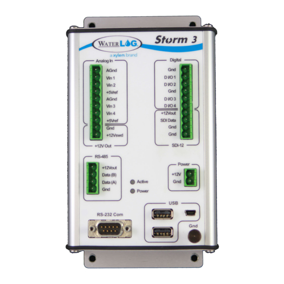
01 / GET TO KNOW YOUR STORM 3 What’s in the Box Hardware: Left Side Hardware: Right Side... - Page 5 Get to Know Your Storm 3 The WaterLOG® Storm 3 is a mid-range data logger with an ideal cost-to-performance ratio. Built with communications in mind, the Storm 3 supports both internal and external cellular modems and GOES satellite radios. Its balanced set of I/O includes four analog inputs, four independently configurable digital I/O, SDI-12, RS-485 and RS-232 serial connections.
- Page 6 HARDWARE LEFT SIDE CONNECTIONS...
- Page 7 Get to Know Your Storm 3 Analog There are four analog input channels labeled Vin1 to Vin4. They are grouped in sets of two with each set having a common ground and +5Vref terminal connection. The standard input range for all channels is 0 to 5 volts.
-
Page 8: Hardware: Right Side
HARDWARE RIGHT SIDE CONNECTIONS... - Page 9 Getting To Know Storm 3 Digital I/O The Digital I/O connections can be configured independently as inputs or outputs. In input mode, the signal has an internal pull up resistor of 47K Ohms. This allows a switch closure to ground to activate the input.
-
Page 10: Connect To The Storm 3
02 / CONNECT TO THE STORM 3 LED Indicators USB Wi-Fi Connection USB Cable Connection... - Page 11 Connect To The Storm 3 The Storm 3 contains a built-in graphical user interface, accessible by either a Wi-Fi or cable connection. No special software is needed to access the user interface. All computers, laptops, tablets, smart phones, and other equipment containing either a Wi-Fi connection or USB port can communicate with and configure the Storm 3 data logger.
- Page 12 USB CONNECTION USB WiFi Connection To wirelessly connect to the Storm 3 data logger, either plug in the USB Wi-Fi adaptor or, if the Wi-Fi adaptor is already connected to the Storm, press the Wi-Fi button on the front of the Storm to enable the Wi-Fi connection.
- Page 13 Connect To The Storm 3 USB Device Cable Connection To connect directly to the Storm data logger, the supplied USB device cable can be used. The first use of the device cable will require a simple driver to be installed for communication. The driver is stored internally on the Storm and becomes available when the USB device cable is plugged in.
-
Page 14: User Interface
03 / USER INTERFACE Home Page Navigation Set Date & Time Adding & Configuring Sensors Enabling Scanning Download Data... - Page 15 User Interface Home Page Navigation Once connected to the Storm 3 data logger, the above interface will become available within a web browser. The interface is divided into three main components: Navigation Pane The left side contains the navigation pane and any additional screens. Current Screen Content The right side contains the content for the current screen.
- Page 16 SENSORS Adding & Configuring Sensors The Storm 3 data logger uses a set of sensor libraries to quickly and easily configure the system. Sensors can be added and configured by pressing the Sensors button near the bottom of the navigation pane. New sensors can be added by selecting a sensor from the available dropdowns.
- Page 17 User Interface Enabling Scanning After setting up each sensor and enabling the desired output options, scanning should be enabled to begin the measurement and data collection process. On the Home > System Overview screen, next to the System Time, select “Enabled” from the Scanning dropdown box.
- Page 18 For more information on how Xylem can help you, go to www.xyleminc.com YSI Incorporated 1700/1725 Brannum Lane...
Need help?
Do you have a question about the YSI Storm 3 and is the answer not in the manual?
Questions and answers