Advertisement
Quick Links
Receive Portable
Flag Antenna Kit
DXE-NOISELOOP
DXE-NOISELOOP-INS-Series Rev 0a
DX Engineering 2021
1200 Southeast Ave. - Tallmadge, OH 44278 USA
Phone: (800) 777-0703 ∙ Tech Support and International: (330) 572-3200
Fax: (330) 572-3279 ∙ E-mail: DXEngineering@DXEngineering.com
Advertisement

Subscribe to Our Youtube Channel
Related Manuals for DX Engineering DXE-NOISELOOP-INS Series


Summary of Contents for DX Engineering DXE-NOISELOOP-INS Series
- Page 1 DX Engineering 2021 1200 Southeast Ave. - Tallmadge, OH 44278 USA Phone: (800) 777-0703 ∙ Tech Support and International: (330) 572-3200 Fax: (330) 572-3279 ∙ E-mail: DXEngineering@DXEngineering.com...
- Page 2 Introduction The DX Engineering Receive Portable Flag Antenna kit is based on the design by Don Kirk, WD8DSB. Don’s article on this antenna is published in the March, 2021 issue of QST Magazine. The Portable Flag has become a real game changer in direction finding of RFI on MF and HF frequencies, and you will also find it an invaluable tool when hunting RFI due to the following key features.
-
Page 3: Safety Considerations
PCB, Resistor Coax Cable, RG-58AU, BNC Male Connector Installed P-Clamp, Stainless Steel, 0.3125” DX Engineering Hardware - includes the following: Resistor, 680 ohm, 1/4 w 2 - Hex Nut - Stainless Steel, 1/4-20 Shrink Tube with Adhesive, 3/8” OD, 1.5” Length 2 - Flat Washer - Stainless Steel, 1/4”... - Page 4 Assembling the Receive Portable Flag Antenna 1. Assemble the transformer core using the following components: Binocular Core, Teflon Tube, Green Magnet Wire and Red Magnet Wire. The core is made into a transformer that uses the Green wire as the Secondary and the Red wire as the Primary, 2.
- Page 5 5. Attach the double sided tape to the feed point PCB, as shown. Then remove the top paper exposing the adhesive. 6. Press the transformer on the double sided tape on to the feed point PCB and run the wires through the feed point PCB as shown.
- Page 6 9. Using the 13 feet of the black antenna wire, cut it in half to make 2 wires the same length. Strip approximately 1/4” to 3/8” off one end of each wire. 10. Route one wire through the resistor PCB as shown and trim as needed. Route the second wire through the resistor PCB as shown, solder the two ends in place and trim as needed.
- Page 7 15. Using the element clamp with mounting stud, install one to the each of the ends of the 1/2” OD fiberglass rods as shown. Note the direction of the mounting studs. One set is the opposite direction than the other. This keeps the antenna wire centered front to back. Tighten the element clamps in place.
- Page 8 18. Use the feed point PCB on the other side of the loop and route the antenna wires through the guides and then through the feed point PCB keeping the feed point PCB centered between the rods. Ensure the resistor PCB is still also centered. Snug up the wires and make a small mark on each wire just above where it passes through the PCB eyelets that will be soldered.
- Page 9 20. Install the 1-1/2” fiberglass rod (handle for the antenna) to the center board using the saddle clamps as shown below. Evenly tighten the U-Bolts in place. Do not over tighten. 21. Route the coaxial cable as shown and use a zip tie to hold it in place.
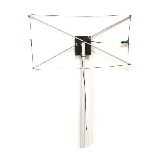
- Page 10 Overall View of completed Receive Loop antenna Optional Pre-Amplifier and Attenuator A perfect companion to the DXE-NOISELOOP is the optional Pre-Amplifier/Attenuator DXE-NL-PRE-ATT-1. It uses an internal 9 volt battery, has BNC connectors for Input and Output, Easy to use slide switches and a power on LED when the Pre-Amp is turned on.
- Page 11 When testing was being done at DX Engineering, an ICOM IC-705 was used because that radio is portable, easy to use and has the ability to display the selected spectrum display as an added feature when tracking down an offending HF signal.
-
Page 12: Manual Updates And Information
All products manufactured by DX Engineering are warranted to be free from defects in material and workmanship for a period of one (1) year from date of shipment. DX Engineering’s sole obligation under these warranties shall be to issue credit, repair or replace any item or part thereof which is proved to be other than as warranted; no allowance shall be made for any labor charges of Buyer for replacement of parts, adjustment or repairs, or any other work, unless such charges are authorized in advance by DX Engineering.
Need help?
Do you have a question about the DXE-NOISELOOP-INS Series and is the answer not in the manual?
Questions and answers