Advertisement
Quick Links
Near Vertical
Incidence
Skywave
(NVIS)
Antenna
DXE-NVIS-8040
DXE-NVIS-8040S
DXE-NVIS-8040NM
DXE-NVIS-8040SNM
DXE-NVIS-INS Revision 1
© DX Engineering 2019
1200 Southeast Ave. - Tallmadge, OH 44278 USA
Phone: (800) 777-0703 ∙ Tech Support and International: (330) 572-3200
Fax: (330) 572-3279 ∙ E-mail: DXEngineering@DXEngineering.com
Advertisement

Related Manuals for DX Engineering DXE-NVIS-8040NM


Summary of Contents for DX Engineering DXE-NVIS-8040NM
- Page 1 Near Vertical Incidence Skywave (NVIS) Antenna DXE-NVIS-8040 DXE-NVIS-8040S DXE-NVIS-8040NM DXE-NVIS-8040SNM DXE-NVIS-INS Revision 1 © DX Engineering 2019 1200 Southeast Ave. - Tallmadge, OH 44278 USA Phone: (800) 777-0703 ∙ Tech Support and International: (330) 572-3200 Fax: (330) 572-3279 ∙ E-mail: DXEngineering@DXEngineering.com...
- Page 2 Introduction DX Engineering’s Near Vertical Incidence Skywave (NVIS) Antennas for both 80 and 40 meters are available in two models. The difference between the two models is the foot print size area needed. The larger version the DXE-NVIS-8040 is a full size 80 and 40 meter NVIS antenna that uses no coils.
- Page 3 NVIS antennas which make them ideal for close in communications (not for DXing). The DX Engineering versions of the NVIS antenna have been designed and tested in real-world situations and found to offer great performance for NVIS communications on both 80 and 40 meters.
- Page 4 WARNING! INSTALLATION OF ANY ANTENNA NEAR POWER LINES IS DANGEROUS Warning: Do not locate the antenna near overhead power lines or other electric light or power circuits, or where it can come into contact with such circuits. When installing the antenna, take extreme care not to come into contact with such circuits, because they may cause serious injury or death.
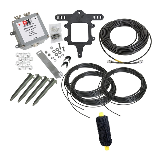
- Page 5 Plus the common parts listed above NOTE: For those that have their own non-metallic 15 foot mast, you can purchase the NVIS antenna kits with all the parts except the mast assembly. Part numbers for those antenna kits are: DXE-NVIS-8040NM and DXE-NVIS-8040SNM. DXE-NVIS-8040NM DXE-NVIS-8040SNM...
-
Page 6: Manual Updates
Every effort is made to supply the latest manual revision with each product. Occasionally a manual will be updated between the time your DX Engineering product is shipped and when you receive it. Please check the DX Engineering web site (www.DXEngineering.com) for the latest revision manual. - Page 7 Installing the Coaxial Cable and Coaxial Cable Strain Relief 1. The DXE-CSR8X-1 Cable Strain Relief has the parts needed to mount to the previous assembly. The assembly will be slightly different that what is described in the DXE-CSR8X-1 instructions. 2. Connect one end of the DXE-8XDX100 coaxial cable to the BALUN. Fully insert the PL-259 to the balun and tighten the collar.
- Page 8 8. Mount the second Studded Band Clamp to the top of the Balun Mounting Bracket using two large Flat Fender Washers and one Nyloc hex nut as shown. Preparing the 40 meter Wire Elements 1. Both models of the NVIS antenna (DXE-NVIS-8040 and DXE-NVIS-8040S) use the same lengths of antenna wire for 40 meters.
- Page 9 DXE-NVIS-8040S 2. The uses two coils. There are four wires for 80 meters. After assembly, each leg of the dipole will be approximately 32 feet. 16 feet in length between the BALUN and the 80 Meter Coil and another wire, approximately 16 feet from the coil to the end insulator. 3.
- Page 10 Attaching the antenna element Wires to the Balun Both models (DXE-NVIS-8040 and DXE-NVIS-8040S) use the same method for attaching the antenna wires to the balun. Wires A and B are connected to the BALUN for the DXE-NVIS-8040 Wires A and C are connected to the BALUN for the DXE-NVIS-8040S Attaching the 40 and 80 meter Wires for the DXE-NVIS-8040 1.
- Page 11 Attaching the 40 meter Wires and the 80 meter Coils for the DXE-NVIS-8040S Install one 40 meter wire (A) and one 80 meter wire with two terminals (C) in each side of the Balun Bracket for the DXE-NVIS-8040S as shown. Note in the previous picture, how the wires route through the three serpentine slots.
-
Page 12: Mast Assembly
NOTE: For those that have their own non-metallic 15 foot mast, you can purchase the NVIS antenna kits with all the parts except the mast assembly. Part numbers for those antenna kits are: DXE-NVIS-8040NM and DXE-NVIS-8040SNM. The NVIS Mast Assembly is the same for both the DXE-NVIS-8040 and DXE- NVIS-8040S NVIS antennas. - Page 13 Mounting the BALUN to the top of the Mast Loosen the band clamps on the Balun Mounting Bracket and install the bracket to the top mast section as shown. The top element clamp will be even with the bottom of the previously installed vinyl cap.
- Page 14 Attaching the End Insulators with ropes to the NVIS Antenna Elements Attach one end insulator with rope to each of the four antenna elements. Since you will change lengths on the wires during tuning, do not cut any wires at this time. Insert each wire through the end insulator and then wrap the wire back on itself as shown below.
- Page 15 Setting up the NVIS Antenna It is advisable to use two people when setting up the NVIS antenna to ensure the mast is held vertically in place while the ropes and tent stakes are installed as shown in the diagrams. Note how the antenna wire elements are in reference to the Balun Mounting Bracket.
- Page 16 The following shows side views for the DXE-NVIS-8040 antenna. - 16 -...
- Page 17 The following shows side views for the DXE-NVIS-8040S antenna. - 17 -...
- Page 18 Tuning Using a good quality Antenna Analyzer, connect the coaxial cable coming from the NVIS antenna. 40 Meters: Sweep the antenna for 40 meters to see where the SWR dip is located. Ideally, you will want the 40 meter dip to be near the lower end or mid range on the 40 meter band. If you are specifically going to use one frequency, then adjust for that frequency for best results.
- Page 19 Transporting the NVIS Antenna The DX Engineering NVIS antennas can be collapsed, wires wrapped and made ready for transport without disassembling the entire antenna. This makes these antennas a viable option for on-the-go emergency or portable operation. Loosen the upper band clamp on one of the telescoping clamps to allow the section to telescope inside the larger tube, snug the clamp in place, then do the same for the other clamps.
-
Page 20: Technical Support
All products manufactured by DX Engineering are warranted to be free from defects in material and workmanship for a period of one (1) year from date of shipment. DX Engineering’s sole obligation under these warranties shall be to issue credit, repair or replace any item or part thereof which is proved to be other than as warranted;...
Need help?
Do you have a question about the DXE-NVIS-8040NM and is the answer not in the manual?
Questions and answers