Table of Contents
Advertisement
Quick Links
Active Receive Antenna
Vertical Configuration
.
DXE-ARAV3-1P - Single Vertical Antenna
DXE-ARAV3-2P - Two Vertical Array Package (for use with NCC-1)
DXE-ARAV3-4P - Four Vertical Array Package
DXE-ARAV3-8P - Eight Vertical Array Package
(Export Models: DXE-ARAV3-1PE, DXE-ARAV3-2PE, DXE-ARAV3-4PE, DXE-ARAV3-8PE)
Used under US Patent No. 7,423,588
DXE-ARAV3-INS-Revision 4c
© DX Engineering 2013
P.O. Box 1491 ∙ Akron, OH 44309-1491 USA
Phone: (800) 777-0703 ∙ Tech Support and International: (330) 572-3200
Fax: (330) 572-3279 ∙ E-mail: DXEngineering@DXEngineering.com
- 1 -
Advertisement
Table of Contents

Related Manuals for DX Engineering DXE-ARAV3-1P


Summary of Contents for DX Engineering DXE-ARAV3-1P
- Page 1 Active Receive Antenna Vertical Configuration DXE-ARAV3-1P - Single Vertical Antenna DXE-ARAV3-2P - Two Vertical Array Package (for use with NCC-1) DXE-ARAV3-4P - Four Vertical Array Package DXE-ARAV3-8P - Eight Vertical Array Package (Export Models: DXE-ARAV3-1PE, DXE-ARAV3-2PE, DXE-ARAV3-4PE, DXE-ARAV3-8PE) Used under US Patent No. 7,423,588 DXE-ARAV3-INS-Revision 4c ©...
-
Page 2: Table Of Contents
Table of Contents Introduction Location Considerations General Information Systems Packages DXE-ARAV3-1P Single Active Receiver DXE-ARAV3-2P Two Active Receivers DXE-ARAV3-4P Four Active Receivers DXE-ARAV3-8P Eight Active Receivers Warning Manual Updates Features Technical Description Basic Tools Required Installation Location Assembly Ground Mounting Rod Three Piece 102"... -
Page 3: Introduction
(ARAV3) offer excellent receiving performance from 100 kHz to 30 MHz using a whip antenna element only 102 inches long. DX Engineering’s unique design makes it vastly superior to traditional active antennas in both strong signal handling and feedline decoupling, providing significantly better weak signal reception due to lower spurious signal interference and reduced noise. -
Page 4: General Information
Systems Packages There are 4 Vertical Active Receive system packages. (DXE-ARAV3-1P, -2P, -4P, -8P) Note: Export versions have a -E after the part number and contain the DXE-WP102E three piece antenna element rather than the one piece antenna element. The three section tapered stainless steel whip with machined couplers was designed to be compact in size for economical export shipping purposes. -
Page 5: Dxe-Arav3-2P Two Active Receivers
DXE-ARAV3-2P - The two active antennas system package DXE-ARAV3-2P is intended to be used with the optional DXE-NCC-1 Noise/Phase Controller to make a steerable dual vertical array. The NCC-1 can also provide power for the active antennas and the proper transmit power-off sequencing. -
Page 6: Manual Updates
Every effort is made to supply the latest manual revision with each product. Occasionally a manual will be updated between the time your DX Engineering product is shipped and when you receive it. Please check the DX Engineering web site (www.DXEngineering.com) for the latest revision manual. -
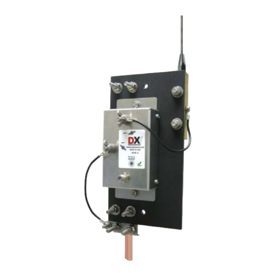
Page 7: Basic Tools Required
Assembly The assembly described is for the DXE-ARAV3-1P. Use UMI-81343 - Anti-Seize on stainless steel hardware threads to prevent galling and to ensure proper torque. Orient the black mounting plate with the two brass element mounting block holes closer to the top left, as shown in Figure 1. - Page 8 Mount the AVA-2 matching unit with the ANT + terminal toward the top up. Use the 5/8" bolts, a flat washer under each bolt and a flat and split washer under each nut. Refer to Figure 2. Figure 2 Loosely install the two stainless steel V-Clamps on the black mounting plate as shown in Figure 3. Figure 3 Upper Clamp Lower Clamp...
-
Page 9: Ground Mounting Rod
Refer to Figure 4 and install one of the two wires (both are the same length) from the brass block to the AVA-2 antenna ANT + connection, use the wing nut and hand tighten only. The wire is held in place on the brass element block with one 5/16" x 1/2" bolt and one star washer. The closed lug goes on the brass element and the open lug goes on the AVA-2. - Page 10 Install the ground wire hardware and ground wire on the stainless steel V-Clamp with the tab. The other end of this wire goes to the AVA-2 ANT- connection as shown in Figure 6. Figure 6 - 10 -...
-
Page 11: Three Piece 102" Receiving Element - Wp-102E
Three Piece 102" Receiving Elements - WP-102E (Export version) The 102" Stainless Steel Tapered Receiving Element comes in two configurations. The ARAV3-1P has the single piece element and the ARAV3-1PE has the three piece element. The three piece antenna element was manufactured to take advantage of lower export shipping costs. Assembly is required for the three piece version. -
Page 12: Providing A Good Rf Ground
Providing a Good RF Ground This active vertical antenna works well with just a single copper ground rod used as the mounting rod. You can test ground quality by listening to a steady local signal. Attach 15 feet of wire laid in a straight line away from the coaxial feedline. - Page 13 See Appendix A for Radio Interface Options Control lines (usually BCD ) can normally use good quality CAT5e cable (4 twisted pairs of 24 AWG wire) for runs up to 1000 feet. Typical DX Engineering BCD control lines requirements are +12 VDC at 25 milliamps.
-
Page 14: Coaxial Cable Feedline
A DX Engineering 4 Square or 8 Circle will require approximately 250 milliamps (only 4 actives are powered at any one time). When calculating line length, take into consideration the total number of active antennas being powered at any one time in your line length calculations. -
Page 15: Using The Active Receive Verticals In A 4 Square Or 8 Circle Array
Using the Active Receive Verticals in a 4 Square or 8 Circle Array Use the DX Engineering Receive Four Square System (DXE-RFS-3P) and four Active Receive Antennas (DXE-ARAV3-4P system package) to configure a four square vertical array. Power and receiver connections are provided through the RFS-3P system. -
Page 16: Alternate Mounting
In a multi-element array, the internal jumpers are used to increase sensitivity at specific frequencies or to reduce interference from strong broadcast stations. When the ARAV3 is used in a DX Engineering DXE-RFS-3P Four Square Receiving Array or the DXE-RCA8-SYS-4P Receive Eight Circle System, select a jumper setting at least 5% below the frequency in use. -
Page 17: Using The Active Receive Verticals With The Dxe-Ncc-1
DXE-ARAV3-1P Active Receive Vertical is probably operating normally. The DXE-ARAV3-1P is designed to be a very low to no gain, low noise system for greatly improved signal-to-noise performance over a very wide range of frequencies. The installation location should be away from towers, transmitting antennas, metal structures and metal fencing in order to take advantage of the DXE-ARAV3-1P Active Receive Vertical antenna capabilities. -
Page 18: Appendix A -Diagrams
4 radials that are about 15 feet long to the negative terminal ground rod connection on the AVA-2. If this significantly increases signal level, then adding another ground rod and/or more radials, as described in the manual for the DXE-ARAV3-1P, should improve your signal results for all bands. - Page 19 Shortwave Receiver: ARAV3-1P system located greater than 1/2-wavelength from any transmitting antenna, connected to a transceiver with a receive input. - 19 -...
- Page 20 DXE-ARAV3-2P Active Receive Vertical Antenna System (with two ARAV3 Receivers) using a DX Engineering DXE-NCC-1 Receive Antenna Variable Phasing Controller. ARAV3 Receivers must be at least 1/10-wavelength away from any transmit antenna and preferably more than 1/2- wavelength away. The NCC-1 switches the power off during transmit. This configuration allows the operator to selectively null out interference, and thereby enhance the desired received signal direction ability.
- Page 21 Typical DXE-RFS-SYS-4P Receive Four Square System Configuration Shown with optional items. Power connections not shown for clarity. Refer to the DXE-RFS-SYS-4P manual for details. - 21 -...
- Page 22 Typical DXE-RCA8-SYS-4P Receive Eight Circle System Configuration Shown with optional items. Power connections not shown for clarity. Refer to the DXE-RCA8-SYS-4P manual for details. - 22 -...
-
Page 23: Optional Items
DXE-F6 - 75 Ω F-6 Style, Direct Bury Coaxial Cable: Full Spool or Custom Cable Assemblies DX Engineering recommends using a high quality 75 Ω “flooded” F6 type coaxial cable. Flooded style cables have the distinct advantage of automatically sealing small accidental cuts or lacerations of the jacket. Flooding also prevents shield contamination and can be direct-buried. -
Page 24: Technical Support
Warranty All products manufactured by DX Engineering are warranted to be free from defects in material and workmanship for a period of one (1) year from date of shipment. DX Engineering’s sole obligation under these warranties shall be to issue credit, repair or replace any item or part thereof which is proved to be other than as warranted;...
Need help?
Do you have a question about the DXE-ARAV3-1P and is the answer not in the manual?
Questions and answers