Table of Contents
Advertisement
Quick Links
Advertisement
Table of Contents

Related Manuals for DX Engineering DXE-SWA-070


Summary of Contents for DX Engineering DXE-SWA-070
- Page 1 Linear-Loaded Multi-Band Dipole Patent Pending DXE-SWA-070 Revision 3 © DX Engineering 2005 P.O. Box 1491 · Akron, OH 44309-1491 Phone: (800) 777-0703 ·Tech Support and International: (330) 572-3200 Fax: (330) 572-3279 · E-mail: DXEngineering@DXEngineering.com...
-
Page 2: Table Of Contents
Table of Contents Introduction Features Mounting Considerations Installation Feedline Feedline Length Calculator Assembly Cenetr T Support Support Line Antenna Conenctions Wire Element Connections End-Insulator Connections Tuner Connections Tuning Addendum 9-10 Optional Accessories Technical Support and Warranty - 2 -... -
Page 3: Introduction
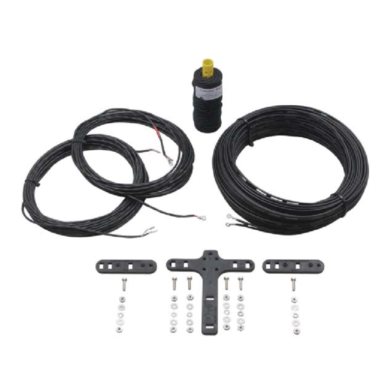
100 feet of premium ladder feedline and 100 feet of double-braided UV-resistant Dacron mounting rope. Stainless steel hardware is used for all connections. The DX Engineering Linear-Loaded Multi-Band Dipole can be used successfully with the balun incorporated in most high quality antenna tuners to obtain a low SWR across the entire frequency range. -
Page 4: Feedline
Feedline The DX Engineering Linear-Loaded Multi-Band Dipoles include 100 feet of high quality 300 Ω ladder line. Depending on your specific installation, this feedline will need to be shortened or lengthened. -
Page 5: Feedline Length Calculator
If you need additional feedline, 100 foot rolls of 300 Ω feedline (DX Engineering part number DXE-LL300-1C) and a convenient line coupler (part number DXE-LLC-1P) are available. This coupler includes a high impact, insulated splice block, ring terminals and stainless hardware, permitting strong and consistent splices of ladder line. -
Page 6: Assembly Cenetr T Support
Assembling the Dipole Center-T Support The center-T support has pre-drilled holes for attachment of the wire elements, feedline and support rope. Support Line The center-T support’s top hole is used for the attachment of a messenger line that is used to provide support for the antenna wire and feedline. -
Page 7: Antenna Conenctions
Locate the ends of the wire elements marked with red tape. These ends connect to the center-T support. With the DX Engineering Logo on the center-T support facing up, feed this element wire down through one side of the notched slot of the center-T support. Next, route the element wire back up through the inner slot and attach the red wire lug to the lower left terminal. -
Page 8: End-Insulator Connections
Install hardware and wire element ends as shown in Figure 4. Figure 4: Assembled End Bracket With the DX Engineering.com lettering facing down, and the notched edge of the end slot facing up, route the wire down through the notched end slot, back up through the next slot, down around the bracket and back up through the slot between the mounting hardware. - Page 9 A high quality 4:1 current balun is ideal for this antenna and is available from DX Engineering (part number DXE-BAL200-H10-AT). This balun provides better balance, often has lower loss, and is more tolerant to load impedance and balance variations than most internal tuner baluns.
-
Page 10: Optional Accessories
DX Engineering Current Baluns • 5, 10 and 10 KW+ Baluns and Current Chokes • High efficiency, low loss—W8JI design • All ratios available Feedline Current Chokes • Reduce RFI and pattern distortion • Prevent feedline radiation … … ½... - Page 11 PolyPhaser Lightning Protectors • 50 Ω DC Block, 1.5-400 MHz, UHF connectors PPC-IS-50UX-C0 Flange Mount, 2 KW at HF PPC-IS-B50HU-C0 Bulkhead Mount, 3 KW at HF PPC-IS-B50LU-C0 Bulkhead Mount, 2 KW at HF PPC-IS-B50LN-C0 Flange Mount, Type N, 2 KW PPC-IS-RCT Rotor Control, 8-line Copper Ground Strap and Clamps •...
-
Page 12: Technical Support And Warranty
All products manufactured by DX Engineering are warranted to be free from defects in material and workmanship for a period of one (1) year from date of shipment. DX Engineering’s sole obligation under these warranties shall be to issue credit, repair or replace any item or part thereof which is proved to be other than as warranted; no allowance shall be made for any labor charges of Buyer for replacement of parts, adjustment or repairs, or any other work, unless such charges are authorized in advance by DX Engineering.
Need help?
Do you have a question about the DXE-SWA-070 and is the answer not in the manual?
Questions and answers