Sign In
Upload
Manuals
Brands
MKS Manuals
Control Unit
T3PIA
MKS T3PIA Manuals
Manuals and User Guides for MKS T3PIA. We have
2
MKS T3PIA manuals available for free PDF download: Instruction Manual, Supplement Manual
MKS T3PIA Instruction Manual (70 pages)
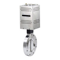
Pendulum Valve with Analog/TTL Interface
Brand:
MKS
| Category:
Control Unit
| Size: 1 MB
Table of Contents
Table of Contents
5
Valve Safety Information
9
Symbols Used in this Instruction Manual
9
Symbols Found on the Unit
9
Safety Procedures and Precautions
9
Table 1: Definition of Symbols Found on the Unit
9
Sicherheitshinweise für das Ventil
11
In dieser Betriebsanleitung Vorkommende Symbole
11
Erklärung der am Gerät Angebrachten Symbole
11
Sicherheitsvorschriften und Vorsichtsmaßnahmen
11
Tabelle 2: Bedeutung der am Gerät Angebrachten Symbole
11
Informations de Sécurité Relatives Au Manomètre
13
Symboles Utilisés Dans Ce Manuel D'utilisation
13
Symboles Figurant Sur L'unité
13
Mesures de Sécurité Et Précautions
13
Tableau 3: Définition des Symboles Sur L'unité
13
Medidas de Seguridad del Manómetro
15
Símbolos Usados en Este Manual de Instrucciones
15
Símbolos Hallados en la Unidad
15
Procedimientos y Precauciones de Seguridad
15
Tabla 4: Definición de Los Símbolos Hallados en la Unidad
15
Chapter One: General Information
17
Introduction
17
Table 5: Definitions
17
How this Manual Is Organized
18
Customer Support
18
Chapter Two: Installation
19
Unpacking the Type T3P Unit
19
Interface Cables
19
Figure 1: Preferred Method to Connect an Overall Metal Braided Shielded Cable
20
Product Location and Requirements
21
Figure 2: Alternate Method to Connect an Overall Metal Braided Shielded Cable
21
Setup
22
Figure 3: Typical System Configuration
22
Table 6: Maximum Torque Levels When Mounting with the Centering Ring and Spacer Ring
23
Table 7: Maximum Torque Levels When Mounting with the O-Ring in Groove
23
Table 8: Admissible Forces
23
Table 9: Mounting Screw Length
24
Table 10: Required Air Pressure Based on Valve Size
24
Setup Procedures
25
Electrical Information
26
Figure 4: Top Panel of the T3P Unit
27
Table 11: Auxiliary Connector Pin out
28
Table 12: Analog Sensor 1 (High) Connector Pin out
29
Table 13: Analog Sensor 2 (Low) Connector Pin out
30
Table 14: Power Connector Pin out
30
Startup
31
Table 15: Differential Pressure
31
Chapter Three: Product Overview
33
General Information
33
Control Mode
33
Figure 5: Typical Pressure Response in LEARN Mode
35
Figure 6. Typical Chamber Pump Speed Curve
35
Figure 7: Phase Set too High
36
Figure 8: Phase Set too Low
36
Figure 9: Gain Set too High
37
Figure 10: Gain Set too Low
37
Trip Points
38
Figure 11: Trip Point Direction Set Low
39
Figure 12: Trip Point Direction Set High
39
Top Panel Components
40
Figure 13: Top Panel of the T3P Unit
40
Table 16: Position Status LED Indicators
41
Table 17: Pressure Status LED Indicators
41
Labels
42
Figure 14: Pump Label
42
Figure 15: Serial Number Label
42
Chapter Four: Analog/Ttl Operation
43
General Information
43
Selecting the Digital Input Functions
43
Table 18: Digital Input Functions
43
Setting the Analog Set Point Inputs
44
Selecting the Digital Output Functions
44
Using RS-232 Commands with an Analog T3P
44
Table 19: Digital Output Functions
44
Chapter Five: Maintenance and Troubleshooting
45
General Information
45
Maintenance
45
Preventive Maintenance
45
Figure 16: Four (4) Valve Cover Screws
46
Figure 17: Gate Bolt
46
Figure 18: Handle
47
Figure 19: Seal Ring Removal
47
Figure 20: Lubricating O-Ring Groove
48
Table 20: Seal Ring Quantity of Grease
48
Table 21: O-Ring Quantity of Grease
48
Figure 21: Seal Ring in Valve Body
49
Table 22: Valve Cover Screw Torque
50
Table 23: Software Command Reference
50
Figure 22: Removing Phillips Head Screws
51
Figure 23: Removing Battery Pack from Device
51
Figure 24: Installing the New Battery Pack
52
Troubleshooting
53
Appendix A: Product Specifications
55
Appendix B: Model Code Explanation
57
Model Code
57
Appendix C: Dimensions
59
Index
69
Advertisement
MKS T3PIA Supplement Manual (59 pages)
With RS-232 Interface
Brand:
MKS
| Category:
Control Unit
| Size: 1 MB
Table of Contents
English
5
Table of Contents
5
Valve Safety Information
7
Symbols Used in this Instruction Manual
7
Symbols Found on the Unit
7
Safety Procedures and Precautions
7
Table 1: Definition of Symbols Found on the Unit
7
Tabelle 2: Bedeutung der am Gerät Angebrachten Symbole
9
Tableau 3: Définition des Symboles Sur L'unité
11
Tabla 4: Definición de Los Símbolos Hallados en la Unidad
13
Chapter One: Remote RS-232 Operation
15
RS-232 Protocol
15
Special Commands Supported (Version 01.04.00 and Newer)
16
Table 5: Message Syntax
16
Setup Messages
18
Table 6: RS-232 Setup Messages
18
Table 7: Sensor Range Values
29
Chamber Pump Speed
30
Setpoint Messages
33
Table 8: Setpoint Messages
33
(Code Version 01.04.08 or Newer)
42
Control Messages
43
Table 9: RS-232 Control Messages
43
Slow Pump Introduction
48
Slow Pump Behavior
49
Activation of Slow Pump
50
Valve.informational Messages
50
Informational Messages
51
Table 10: RS-232 Informational Messages
51
Chapter Two: RS-232 Message Summary
55
German
9
Sicherheitshinweise für das Ventil
9
In dieser Betriebsanleitung Vorkommende Symbole
9
Erklärung der am Gerät Angebrachten Symbole
9
Sicherheitsvorschriften und Vorsichtsmaßnahmen
9
French
11
Informations de Sécurité Relatives Au Manomètre
11
Symboles Utilisés Dans Ce Manuel D'utilisation
11
Symboles Figurant Sur L'unité
11
Mesures de Sécurité Et Précautions
11
Spanish
13
Medidas de Seguridad del Manómetro
13
Símbolos Usados en Este Manual de Instrucciones
13
Símbolos Hallados en la Unidad
13
Procedimientos y Precauciones de Seguridad
13
Advertisement
Related Products
MKS T3B Series
MKS T3P Series
MKS T3BIA
MKS T3BIB
MKS T3PIB
MKS TFT35
MKS MKS TFT28
MKS MKS TFT32
MKS TFT24
MKS 248A
MKS Categories
Controller
Measuring Instruments
Transducer
Control Unit
Industrial Equipment
More MKS Manuals
Login
Sign In
OR
Sign in with Facebook
Sign in with Google
Upload manual
Upload from disk
Upload from URL