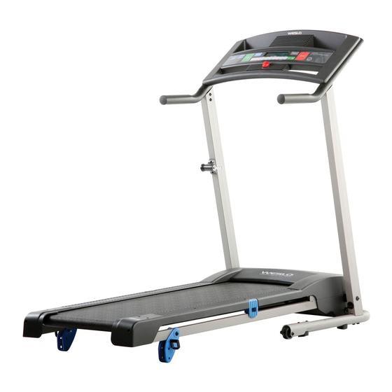
Weslo cadence G-40 User Manual
Hide thumbs
Also See for cadence G-40:
- Manual (29 pages) ,
- User manual (28 pages) ,
- User manual (28 pages)
Advertisement
Table of Contents
- 1 Table of Contents
- 2 Warning Decal Placement
- 3 Important Precautions
- 4 Before You Begin
- 5 Assembly
- 6 Operation and Adjustment
- 7 How to Fold and Move the Treadmill
- 8 Troubleshooting
- 9 Exercise Guidelines
- 10 Part List
- 11 Exploded Drawing
- 12 Ordering Replacement Parts
- 13 Limited Warranty
- Download this manual
www.weslo.com
Model No. WLTL29606.8
Serial No.
Write the serial number in the space
above for future reference.
Serial Number
Decal
QUESTIONS?
If you have questions, or if parts are
damaged or missing, DO NOT CON-
TACT THE STORE; please contact
Customer Care.
IMPORTANT: Please register this
product (see the limited warranty
on the back cover of this manual)
before contacting Customer Care.
1-866-699-3756
CALL TOLL-FREE:
Mon.–Fri. 6 a.m.–6 p.m. MT
Sat. 8 a.m.–4 p.m. MT
ON THE WEB:
www.wesloservice.com
CAUTION
Read all precautions and instruc-
tions in this manual before using
this equipment. Save this manual
for future reference.
USER'S MANUAL
Advertisement
Table of Contents

Related Manuals for Weslo cadence G-40


Summary of Contents for Weslo cadence G-40
- Page 1 USER'S MANUAL Model No. WLTL29606.8 Serial No. Write the serial number in the space above for future reference. Serial Number Decal QUESTIONS? If you have questions, or if parts are damaged or missing, DO NOT CON- TACT THE STORE; please contact Customer Care.
-
Page 2: Table Of Contents
Apply the decal in the location shown. Note: The decal(s) may not be shown at actual size. WESLO is a registered trademark of ICON IP, Inc. -
Page 3: Important Precautions
14. To purchase a surge suppressor, see your local WESLO dealer or call the telephone 3. Use the treadmill only as described. number on the front cover of this manual and order part number 146148, or see your local 4. - Page 4 19. The treadmill is capable of high speeds. 25. Never drop or insert any object into any Adjust the speed in small increments to avoid opening on the treadmill. DANGER: sudden jumps in speed. Always unplug the power 20. Never leave the treadmill unattended while it cord immediately after use, before cleaning is running.
-
Page 5: Before You Begin
CADENCE ing this manual, please see the front cover of this man- ® G-40 treadmill. The CADENCE G-40 treadmill offers a ual. To help us assist you, note the product model selection of features designed to make your workouts number and serial number before contacting us. The at home more effective. -
Page 6: Assembly
ASSEMBLY To hire an authorized service technician to assemble the treadmill, call 1-800-445-2480. Assembly requires two persons. Set the treadmill in a cleared area and remove all packing materials. Do not dispose of the packing materials until assembly is completed. Note: The underside of the treadmill walking belt is coated with high-performance lubricant. - Page 7 1. Make sure that the power cord is unplugged. Place a piece of cardboard under the tread- mill frame to protect the floor during assem- bly. Have a second person hold the Base (52) in the position shown. Attach six Base Pads (63) to the Base (52) with six 19mm Tek Screws (26).
- Page 8 3. Slide the two Wheel Housings (45) onto the Base (52). Attach each Wheel Housing with two M6 x 58mm Bolts (13), two M6 Flat Washers (32), and two M6 Nuts (43). 4. Remove the bolts and the cardboard packaging from both sides of the Hood (65).
- Page 9 5. See the left inset drawing and identify a Frame Spacer (11). Hold the Frame Spacer between the Right Upright (54) and the Frame (51). Attach the Right Upright to the Frame with an M10 x 110mm Bolt (1), an M10 Flat Washer (14), and an M10 Star Washer (9);...
- Page 10 7. Set the Console (91) face down on a soft sur- face to avoid scratching it. Hold the Right Handrail (33), which has a large hole in the loca- Connector Console Wire tion shown, near the Console. Bracket Large Next, insert the console wire into the large hole Hole in the side of the Right Handrail (33).
- Page 11 9. With the help of a second person, hold the Console (91) near the Right Upright (54). Remove the wire ties from the Wire Harness (39) and the console wire. Connect the Wire Harness to the console wire. See the inset drawing.
- Page 12 11. Start an M8 x 15mm Bolt (8) with an M8 Star Washer (5) into each Upright (53, 54). Then, firmly tighten all six M8 x 15mm Bolts (8). With the help of a second person, carefully lower the Uprights (53, 54) to the floor. 12.
- Page 13 13. Attach the Latch Housing (48) to the Left Upright (53) with two #10 x 1" Tek Screws (58); start both Tek Screws, and then tighten each of them. 14. Raise the treadmill to the storage position (see HOW TO FOLD THE TREADMILL on page 19). Attach an Incline Leg (95) to each side of the Frame (51) with an M8 x 52mm Bolt (82), two M8 Flat Washers (72), and an M8 Nut (46) as...
-
Page 14: Operation And Adjustment
OPERATION AND ADJUSTMENT THE PRE-LUBRICATED WALKING BELT that is properly installed and grounded in accor- dance with all local codes and ordinances. IMPORTANT: The treadmill is not compatible with Your treadmill features a walking belt coated with high- performance lubricant. IMPORTANT: Never apply sil- GFCI-equipped outlets. - Page 15 CONSOLE DIAGRAM Thumb Pulse Sensor Clip FEATURES OF THE CONSOLE HOW TO TURN ON THE POWER IMPORTANT: If the treadmill has been exposed to The treadmill console offers a selection of features cold temperatures, allow it to warm to room tem- designed to make your workouts more effective.
- Page 16 HOW TO USE THE MANUAL MODE tors around the track will appear in succession until the entire track appears. The track will then disap- 1. Insert the key into the console. pear and the indicators will again begin to appear in succession.
- Page 17 HOW TO USE A SPEED PROGRAM Note: The console can display speed and dis- 1. Insert the key into the console. tance in either miles or kilometers. To see which unit of measure- See HOW TO TURN ON THE POWER on page 15. ment is selected, first 2.
- Page 18 If the speed setting is too high or too low during the HOW TO CHANGE THE INCLINE OF THE TREADMILL program, you can manually override the setting by pressing the speed buttons. However, when the To vary the intensity of your exercise, you can change next period begins, the speed of the walking the incline of the treadmill.
-
Page 19: How To Fold And Move The Treadmill
HOW TO FOLD AND MOVE THE TREADMILL HOW TO FOLD THE TREADMILL HOW TO MOVE THE TREADMILL Before folding the treadmill, unplug the power Before moving the treadmill, fold it as described at the cord. CAUTION: You must be able to safely lift 45 left. -
Page 20: Troubleshooting
TROUBLESHOOTING Most treadmill problems can be solved by following the steps below. Find the symptom that applies, and follow the steps listed. If further assistance is needed, please see the front cover of this manual. PROBLEM: The power does not turn on SOLUTION: a. - Page 21 PROBLEM: The walking belt slows when walked on SOLUTION: a. Use only a single-outlet surge suppressor that meets all of the specifications described on page 14. b. If the walking belt is overtightened, treadmill perfor- mance may decrease and the walking belt may be- 2–3 in.
-
Page 22: Exercise Guidelines
EXERCISE GUIDELINES WARNING: Burning Fat—To burn fat effectively, you must exer- cise at a low intensity level for a sustained period of Before beginning any time. During the first few minutes of exercise, your exercise program, consult your physician. body uses carbohydrate calories for energy. Only after This is especially important for persons over the first few minutes of exercise does your body begin the age of 35 or persons with pre-existing... -
Page 23: Part List
PART LIST—Model No. WLTL29606.8 R0910A Key No. Qty. Description Key No. Qty. Description M10 x 110mm Bolt Base M10 x 58mm Bolt Left Upright Wire Tie Screw/Reed Switch Screw Right Upright M4.2 x 16mm Screw Idler Roller M8 Star Washer Motor Belt Warning Decal Electronics Bracket... -
Page 24: Exploded Drawing
EXPLODED DRAWING A—Model No. WLTL29606.8 R0910A... - Page 25 EXPLODED DRAWING B—Model No. WLTL29606.8 R0910A 42 21...
- Page 26 EXPLODED DRAWING C—Model No. WLTL29606.8 R0910A...
- Page 27 EXPLODED DRAWING D—Model No. WLTL29606.8 R0910A...
-
Page 28: Ordering Replacement Parts
ORDERING REPLACEMENT PARTS To order replacement parts, please see the front cover of this manual. To help us assist you, be prepared to pro- vide the following information when contacting us: • the model number and serial number of the product (see the front cover of this manual) •...
Need help?
Do you have a question about the cadence G-40 and is the answer not in the manual?
Questions and answers