Table of Contents
Advertisement
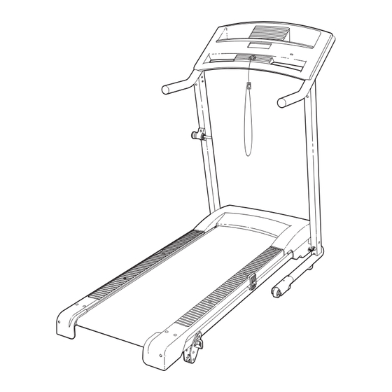
Model No. WCTL29607.0
Serial No.
Write the serial number in the space
above for future reference.
Serial Number
Decal
QUESTIONS?
As a manufacturer, we are com-
mitted to providing complete
customer satisfaction. If you
have questions, or if parts are
damaged or missing, PLEASE
CONTACT OUR CUSTOMER
SERVICE DEPARTMENT
DIRECTLY.
CALL TOLL-FREE:
1-888-936-4266
Mon.–Fri., 8:00 until 17:00 EST
(excluding holidays)
OR E-MAIL US:
customerservice@iconcanada.ca
CAUTION
Read all precautions and instruc-
tions in this manual before using
this equipment. Save this manual
for future reference.
Visit our website at
www.proform.com
Visit our website at
USER'S MANUAL
Visit our website at
www.weslo.com
Visit our website at
Advertisement
Table of Contents

Related Manuals for Weslo WCTL29607.0


Summary of Contents for Weslo WCTL29607.0
- Page 1 Model No. WCTL29607.0 USER'S MANUAL Serial No. Write the serial number in the space above for future reference. Serial Number Decal QUESTIONS? As a manufacturer, we are com- mitted to providing complete customer satisfaction. If you have questions, or if parts are...
-
Page 2: Table Of Contents
Apply the decal in the loca- tion shown. Note: The decal may not be shown at actual size. WESLO is a registered trademark of ICON IP, Inc. -
Page 3: Important Precautions
IMPORTANT PRECAUTIONS WARNING: To reduce the risk of serious injury, read all important precautions and in- structions in this manual and all warnings on your treadmill before using your treadmill. ICON as- sumes no responsibility for personal injury or property damage sustained by or through the use of this product. - Page 4 20. Never leave the treadmill unattended while it 24. Inspect and properly tighten all parts of the is running. Always remove the key, unplug treadmill regularly. the power cord, and switch the reset/off cir- cuit breaker to the off position when the 25.
-
Page 5: Before You Begin
BEFORE YOU BEGIN Thank you for selecting the new WESLO ® CADENCE ing this manual, please see the front cover of this man- G-40 treadmill. The CADENCE G-40 treadmill combines ual. To help us assist you, note the product model advanced technology with innovative design to help you number and serial number before contacting us. -
Page 6: Assembly
2 1/2” Bolt (56)–4 ASSEMBLY Washer (29)–4 Star Washer (81)–4 2 3/4” Bolt (47)–4 Handrail Washer (11)– Assembly requires two persons. Set the treadmill in a cleared area and remove all packing materials; do not dispose of the packing materials until assembly is completed. Note: The underside of the treadmill walking belt is coated with high-performance lubricant. - Page 7 2. Have a second person hold the Base (52) in the position shown. Identify the Left Upright (53) (the Right Upright Large [54] has a large hole near the lower end). Hole Hold the Left Upright (53) so that the two indi- cated small holes are on top.
- Page 8 5. See the left inset drawing. Identify a Frame Spacer (11). Hold the Frame Spacer between the Right Upright (54) and the Frame (51). With the help of a second person, raise the front of the Frame until steps 5 and 6 are completed. Attach the Right Upright (54) to the Frame (51) with an M10 x 110mm Bolt (1), an M10 Flat Washer (14), and an M10 Star Washer (9);...
- Page 9 7. Set the Console (91) face down on a soft sur- face to avoid scratching it. Hold the Right Handrail (33), which has a large hole in the loca- tion shown, near the Console. Console Wire Connector Bracket Next, insert the console wire into the large hole Large in the side of the Right Handrail (33).
- Page 10 9. With the help of a second person, hold the Console (91) near the Right Upright (54). Remove the wire tie from the Wire Harness (39) and the console wire. Connect the Wire Harness to the console wire. See the inset drawing. The connectors should slide together easily and snap into place.
- Page 11 12. See the lower drawing. Position the Uprights (53, 54) so that the treadmill Frame (51) is cen- tered between the Uprights. Firmly tighten the two M10 x 110mm Bolts (1) and the four M10 x 58mm Bolts (2). Be careful not to overtighten the M10 x 110mm Bolts.
-
Page 12: Operation And Adjustment
OPERATION AND ADJUSTMENT THE PRE-LUBRICATED WALKING BELT outlet that is properly installed and grounded in accordance with all local codes and ordinances. Important: The treadmill is not compatible with Your treadmill features a walking belt coated with high- performance lubricant. IMPORTANT: Never apply sil- GFCI-equipped outlets. - Page 13 CONSOLE DIAGRAM Thumb Pulse Sensor Note: If there are sheets of clear plastic on the console, remove the plastic. Clip FEATURES OF THE CONSOLE HOW TO TURN ON THE POWER IMPORTANT: If the treadmill has been exposed to The treadmill console offers a selection of features designed to make your workouts more effective.
- Page 14 HOW TO USE THE MANUAL MODE track will appear in succession until the entire track appears. The track will then disappear and the indi- 1. Insert the key into the console. cators will again begin to appear in succession. The center of the track will show the number of See HOW TO TURN ON THE POWER on page 13.
- Page 15 Note: The console can HOW TO USE A SPEED PROGRAM display speed and dis- 1. Insert the key into the console. tance in either miles or kilometers. To see which unit of measurement is See HOW TO TURN ON THE POWER on page 13. selected, first remove the 2.
- Page 16 If the speed setting is too high or too low during the HOW TO CHANGE THE INCLINE OF THE TREADMILL program, you can manually override the setting by pressing the speed buttons. However, when the To vary the intensity of your exercise, you can change next segment of the workout begins, the tread- the incline of the treadmill.
-
Page 17: How To Fold And Move The Treadmill
HOW TO FOLD AND MOVE THE TREADMILL HOW TO FOLD THE TREADMILL FOR STORAGE Before folding the treadmill, unplug the power cord. CAUTION: You must be able to safely lift 45 lbs. (20 kg) to raise, lower, or move the treadmill. Frame 1. - Page 18 HOW TO LOWER THE TREADMILL FOR USE 1. Hold the upper end of the treadmill with your right hand as shown. Using your left hand, pull the latch knob to the left and hold it. Next, lower the frame until it is past the latch pin.
-
Page 19: Troubleshooting
TROUBLESHOOTING Most treadmill problems can be solved by following the steps below. Find the symptom that applies, and follow the steps listed. If further assistance is needed, please see the front cover of this manual. PROBLEM: The power does not turn on SOLUTION: a. - Page 20 PROBLEM: The walking belt slows when walked on SOLUTION: a. Use only a single-outlet surge suppressor that meets all of the specifications described on page 12. b. If the walking belt is overtightened, treadmill perfor- mance may decrease and the walking belt may be- 2–3 in.
-
Page 21: Exercise Guidelines
EXERCISE GUIDELINES Burning Fat—To burn fat effectively, you must exer- WARNING: cise at a low intensity level for a sustained period of Before beginning this time. During the first few minutes of exercise, your or any exercise program, consult your physi- body uses carbohydrate calories for energy. - Page 22 SUGGESTED STRETCHES The correct form for several basic stretches is shown at the right. Move slowly as you stretch—never bounce. 1. Toe Touch Stretch Stand with your knees bent slightly and slowly bend forward from your hips. Allow your back and shoulders to relax as you reach down toward your toes as far as possible.
-
Page 23: Part List
PART LIST—Model No. WCTL29607.0 R0807A To locate the parts listed below, see the EXPLODED DRAWING near the end of this manual. Key No. Qty. Description Key No. Qty. Description M10 x 110mm Bolt Rear Roller M10 x 58mm Bolt Motor Belt... -
Page 24: Exploded Drawing
EXPLODED DRAWING A—Model No. WCTL29607.0 R0807A... - Page 25 EXPLODED DRAWING B—Model No. WCTL29607.0 R0807A 42 21...
- Page 26 EXPLODED DRAWING C—Model No. WCTL29607.0 R0807A 43 43...
- Page 27 EXPLODED DRAWING D—Model No. WCTL29607.0 R0807A...
-
Page 28: Ordering Replacement Parts
ORDERING REPLACEMENT PARTS To order replacement parts, please see the front cover of this manual. To help us assist you, be prepared to pro- vide the following information when calling: • the model number and serial number of the product (see the front cover of this manual) •...
Need help?
Do you have a question about the WCTL29607.0 and is the answer not in the manual?
Questions and answers