Rice Lake ISHIDA Uni-9 Series Technical Manual
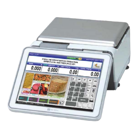
Price computing scale with printer and color touchscreen
Hide thumbs
Also See for ISHIDA Uni-9 Series:
- Operation manual (200 pages) ,
- Installation manual (51 pages)

Related Manuals for Rice Lake ISHIDA Uni-9 Series


Summary of Contents for Rice Lake ISHIDA Uni-9 Series
- Page 1 Uni-9 Series Price Computing Scale with Printer and Color Touchscreen Technical Manual PN 162196...
- Page 3 NOTICES & PRECAUTIONS NOTICES IMPORTANT NOTICE Those who handle the machine must be aware of the hazards involved. These dangers may not be obvious, so it is imperative to follow the instructions detailed in this manual when installing, operating, inspecting, or servicing the machine. Therefore, we recommend that you thoroughly read and understand this manual before installing, operating, inspecting, or servicing the machine.
- Page 4 NOTICES & PRECAUTIONS PRECAUTIONS PRECAUTION SYMBOLS This machine is manufactured for use according to proper procedures by a qualified person and only for the purposes described in this manual. The following conventions are used to indicate and classify precautions depending on the level of danger, or seriousness of potential injury. Always heed the information provided in this manual.
- Page 5 NOTICES & PRECAUTIONS PRECAUTIONS FOR HANDLING • Do not allow water or any liquids to come into contact with the machine. Doing so may result in fire or cause the machine to break down. • Do not drop or apply a strong shock to the machine.
- Page 6 NOTICES & PRECAUTIONS • Handle with care when removing or inserting the cassette. Careless cassette handling may result in injury or cause the cassette to break down. • Do not press the touch panel with an edged thing. Doing so may scratch the panel and cause the machine to break down.
- Page 7 NOTICES & PRECAUTIONS PRECAUTIONS WHEN USING CLEANING FLUIDS Use a soft cloth and a neutral detergent to clean the machine. Do not use thinner, benzene, etc. Doing so may damage the original safety functions. For some parts, use cleaning fluid (isopropyl alcohol). ...
- Page 8 NOTICES & PRECAUTIONS memo UNI-9 Service Manual...
-
Page 9: Table Of Contents
TABLE OF CONTENTS TABLE OF CONTENTS Chapter 1 BASIC INFORMATION OUTER DIMENSIONS FOR EACH TYPE ............. 1-1 1.1.1 OUTER DIMENSIONS FOR BENCH TYPE ..........1-1 1.1.2 OUTER DIMENSIONS FOR LARGE PLATTER TYPE ......... 1-2 1.1.3 OUTER DIMENSIONS FOR ELEVATED TYPE ........... 1-3 1.1.4 OUTER DIMENSIONS FOR POLE TYPE ............. - Page 10 TABLE OF CONTENTS 4.1.3 OPERATION DISPLAY .................. 5-3 4.1.4 USB PORT COVER ..................5-4 4.1.5 CUSTOMER DISPLAY .................. 5-4 4.1.6 MAIN UNIT (POWER BOARD/MAIN BOARD) ..........5-5 4.1.7 OPERATION DISPLAY .................. 5-9 4.1.8 PLATE UNIT....................5-11 4.1.9 THERMAL HEAD ..................5-12 4.1.10 THERMAL HEAD CABLE ................
-
Page 11: Chapter 1 Basic Information
Chapter 1 BASIC INFORMATION BASIC INFORMATION OUTER DIMENSIONS FOR EACH TYPE 1.1.1 OUTER DIMENSIONS FOR BENCH TYPE (unit : mm) UNI-9 Service Manual... -
Page 12: Outer Dimensions For Large Platter Type
Chapter 1 BASIC INFORMATION 1.1.2 OUTER DIMENSIONS FOR LARGE PLATTER TYPE (unit : mm) UNI-9 Service Manual... -
Page 13: Outer Dimensions For Elevated Type
Chapter 1 BASIC INFORMATION 1.1.3 OUTER DIMENSIONS FOR ELEVATED TYPE (unit : mm) UNI-9 Service Manual... -
Page 14: Outer Dimensions For Pole Type
Chapter 1 BASIC INFORMATION 1.1.4 OUTER DIMENSIONS FOR POLE TYPE (unit : mm) UNI-9 Service Manual... -
Page 15: Outer Dimensions For Short Pole Type
Chapter 1 BASIC INFORMATION 1.1.5 OUTER DIMENSIONS FOR SHORT POLE TYPE (unit : mm) UNI-9 Service Manual... -
Page 16: Outer Dimensions For Self-Service Type
Chapter 1 BASIC INFORMATION 1.1.6 OUTER DIMENSIONS FOR SELF-SERVICE TYPE (unit : mm) UNI-9 Service Manual... -
Page 17: Outer Dimensions For Xl Type
Chapter 1 BASIC INFORMATION 1.1.7 OUTER DIMENSIONS FOR XL TYPE (unit : mm) UNI-9 Service Manual... -
Page 18: Specifications
Chapter 1 BASIC INFORMATION SPECIFICATIONS Items Descriptions Use conditions Temperature: 0 to 40°C Humidity: 20 to 85%, Non condensing. Power supply: AC100 – 240V, 50 / 60Hz Power consumption 4.0A/2.0.A Weighing capacity 15 kg: 0 to 6/0.002 kg, 6 to 15/0.005 kg Scale interval 30 lb: 0 to 15/0.005 lb, 15 to 30/0.01 lb Weighting accuracy... -
Page 19: Installation
Chapter 1 BASIC INFORMATION INSTALLATION 1.3.1 POWER SUPPLY It is strongly advised that the following safety measures must be observed to ensure the safe operation of the machine: • Read precaution instructions described in this manual before connecting the power plug into the outlet. -
Page 20: Precautions For Installation
Chapter 1 BASIC INFORMATION 1.3.2 PRECAUTIONS FOR INSTALLATION Do not install the machine in the following types of places: • Places subject to high • Places subject to excessive • Places subject to a lot of temperatures or high humidity vibration or unstable dust or dirt •... -
Page 21: Chapter 2 Assembly Drawings
Chapter 2 ASSEMBLY DRAWINGS ASSEMBLY DRAWINGS BENCH TYPE UNI-9 Service Manual... -
Page 22: Xl Type
Chapter 2 ASSEMBLY DRAWINGS XL TYPE UNI-9 Service Manual... -
Page 23: Pole Unit (Pole/Self-Service/Elavated Type)
Chapter 2 ASSEMBLY DRAWINGS POLE UNIT (POLE/SELF-SERVICE/ELAVATED TYPE) UNI-9 Service Manual... -
Page 24: Short Pole Unit (Short Pole Type)
Chapter 2 ASSEMBLY DRAWINGS SHORT POLE UNIT (SHORT POLE TYPE) UNI-9 Service Manual... -
Page 25: Printer Frame Unit (Each Type)
Chapter 2 ASSEMBLY DRAWINGS PRINTER FRAME UNIT (EACH TYPE) UNI-9 Service Manual... -
Page 26: Cassette Unit (Each Type)
Chapter 2 ASSEMBLY DRAWINGS CASSETTE UNIT (EACH TYPE) UNI-9 Service Manual... - Page 27 Chapter 2 ASSEMBLY DRAWINGS CASSETTE UNIT (EACH TYPE) (without the backing paper) UNI-9 Service Manual...
- Page 28 Chapter 2 ASSEMBLY DRAWINGS memo UNI-9 Service Manual...
-
Page 29: Chapter 3 Block Diagrams
Chapter 3 BLOCK DIAGRAMS BLOCK DIAGRAMS BLOCK DIAGRAM (BENCH TYPE) UNI-9 Service Manual... -
Page 30: Block Diagram (Large Platter Type)
Chapter 3 BLOCK DIAGRAMS BLOCK DIAGRAM (LARGE PLATTER TYPE) UNI-9 Service Manual... -
Page 31: Block Diagram (Elevated Type)
Chapter 3 BLOCK DIAGRAMS BLOCK DIAGRAM (ELEVATED TYPE) UNI-9 Service Manual... -
Page 32: Block Diagram (Pole Type)
Chapter 3 BLOCK DIAGRAMS BLOCK DIAGRAM (POLE TYPE) UNI-9 Service Manual... -
Page 33: Block Diagram (Short Pole Type)
Chapter 3 BLOCK DIAGRAMS BLOCK DIAGRAM (SHORT POLE TYPE) UNI-9 Service Manual... -
Page 34: Block Diagram (Self-Service Type)
Chapter 3 BLOCK DIAGRAMS BLOCK DIAGRAM (SELF-SERVICE TYPE) UNI-9 Service Manual... -
Page 35: Block Diagram (Xl Type)
Chapter 3 BLOCK DIAGRAMS BLOCK DIAGRAM (XL TYPE) UNI-9 Service Manual... - Page 36 Chapter 3 BLOCK DIAGRAMS UNI-9 Service Manual...
-
Page 37: Chapter 4 Machine Disassembly
Chapter 4 MACHINE DISASSEMBLY MACHINE DISASSEMBLY DISASSEMBLY PROCEDURE FOR EACH TYPE CAUTION: Make sure to unplug the power cord from the wall outlet before starting the disassembly work. The procedure of this section is based on that of BENCH TYPE. For the CUSTOMER DISPLAY and OPERATION DISPLAY of ELEVATED TYPE, refer to the section 5.2 ELEVATED TYPE. -
Page 38: Main Unit Cover
Chapter 4 MACHINE DISASSEMBLY 4.1.2 MAIN UNIT COVER Hold up the display to open the cassette Pull out the cassette unit. cover. Remove two screws securing the hinge. Detach the hinge cover (lower). Hold down the display to detach the hinge Remove three screws (green) and two TP cover (upper). -
Page 39: Operation Display
Chapter 4 MACHINE DISASSEMBLY Detach the main unit cover. * Reverse this procedure for assembly. 4.1.3 OPERATION DISPLAY Detach the hinge cover. Remove two screws of display to detach the hinge cover. Loosen two screws securing the hinge to Unplug three connectors of display. detach the display unit. -
Page 40: Usb Port Cover
Chapter 4 MACHINE DISASSEMBLY 4.1.4 USB PORT COVER Open the USB port door. Remove the screw securing the USB port cover. Detach the USB port cover. Unplug the connector connected to the power switch board. * Reverse this procedure for assembly. 4.1.5 CUSTOMER DISPLAY Disengage three hooks located on the bottom Remove two screws. -
Page 41: Main Unit (Power Board/Main Board)
Chapter 4 MACHINE DISASSEMBLY Remove two screws and unplug two Detach the customer-side display unit. connectors. Remove four screws. Detach the customer-side display panel. * Reverse this procedure for assembly. 4.1.6 MAIN UNIT (POWER BOARD/MAIN BOARD) Remove six screws securing the main unit cover. Detach the main unit cover. - Page 42 Chapter 4 MACHINE DISASSEMBLY Unplug the connector and ground wire. Pull out the main unit. Remove two screws securing the power Pull out the power board. board. Unplug two connectors (CN2 and CN3) connected to the main board. CAUTION: Here you need to disassemble the main board unit to unplug the FAN cable installed on the power board.
- Page 43 Chapter 4 MACHINE DISASSEMBLY Remove two screws securing the frame. Remove the screw securing the frame. Unplug the connector (XJ8) connected to the Unplug the connector (XJ20) connected to customer-side display unit. the FAN of the power board. Unplug the connector (XJ13) connected to Unplug the connector (XJ17) connected to the power board.
- Page 44 Chapter 4 MACHINE DISASSEMBLY Unplug the connector (XJ16) connected to the the terminal for connection with the separate-type scale unit. XJ25 and XJ16 are the pair of branch cables. Unplug the connector (XJ23) connected to Unplug the connector (XJ12) connected to the power switch board.
-
Page 45: Operation Display
Chapter 4 MACHINE DISASSEMBLY Detach the main board (remove the screws and detach the frame). Note: Be sure to route the two-conductor power cable for the RF Option to the bottom of the Power Supply * Reverse this procedure for assembly. &... - Page 46 Chapter 4 MACHINE DISASSEMBLY Detach the board P-1118. Remove two connectors and four screws. Detach the plate on which the relay board Detach the touch panel and LCD. is installed. * Reverse this procedure for assembly. 4-10 UNI-9 Service Manual...
-
Page 47: Plate Unit
Chapter 4 MACHINE DISASSEMBLY 4.1.8 PLATE UNIT Remove the screw and TP screw. Detach the plate. Remove four hex screws with the hex Remove five screws to detach the cover. wrench (4mm) to detach the plate. Unplug the connector, disengage two hooks Disengage two hooks with the flat-blade and remove four hex screws. -
Page 48: Thermal Head
Chapter 4 MACHINE DISASSEMBLY 4.1.9 THERMAL HEAD Push the button to open the cassette door. Pull out the cassette unit. Open the thermal head cover. Disengage two hooks to detach the thermal head and then unplug the connector. Detach the thermal head. Note: If necessary use the two 1.5mm allen head set Reverse this procedure for assembly. -
Page 49: Thermal Head Cable
Chapter 4 MACHINE DISASSEMBLY 4.1.10 THERMAL HEAD CABLE Remove two screws securing the cassette Detach the cassette cover. door after detaching the thermal head. Remove the screw located on the bottom Detach the plate. of the main unit. The thermal head cable is connected to the connector (XJ17) on the main board. -
Page 50: Elevated Type
Chapter 4 MACHINE DISASSEMBLY ELEVATED TYPE CAUTION: Make sure to unplug the power cord from the wall outlet before starting the disassembly work. 4.2.1 CUSTOMER DISPLAY Remove two screws (the outer two screws) Detach the cover located on the top of the located on the bottom panel on the top of the pole. - Page 51 Chapter 4 MACHINE DISASSEMBLY Unplug the connector and ground wire. Loosen two screws securing the hinge to detach the customer-side display. Remove four screws securing the hinge. Detach the hinge. Remove six screws securing the display Detach the display cover. cover.
-
Page 52: Operation Display
Chapter 4 MACHINE DISASSEMBLY Detach the LCD from the cover. * Reverse this procedure for assembly. 4.2.2 OPERATION DISPLAY Remove two screws securing the hinge Detach the hinge cover located on the back cover located on the back of the operation of the operation display. - Page 53 Chapter 4 MACHINE DISASSEMBLY Unplug three connectors of display. Loosen two screws securing the hinge to detach the operation display. Remove four screws securing the hinge. Detach the hinge. Remove six screws securing the display Detach the display cover. cover. Unplug two connectors (XJ6 and XJ9) and Detach the board P1102.
- Page 54 Chapter 4 MACHINE DISASSEMBLY Unplug two connectors and remove four Detach the plate on which the relay board is screws. installed. Detach the touch panel and LCD. * Reverse this procedure for assembly. CAUTION: During the reassembly work, make sure not to confuse the operation display with the customer-side display.
-
Page 55: Chapter 5 Optional Unit
Chapter 5 OPTIONAL UNIT OPTIONAL UNIT OPTION LIST PART NAME LARGE PLATTER MODIFICATION KIT MODIFICATION KIT FOR SEPARATE-TYPE PLATTER GUIDE PLATTER WIRELESS LAN KIT USB-I2NET CONVERTER USB-DIN8 CONVERTER USB CONVERTER STAND ANTITHEFT COVER FOR USB FLASH DRIVES USB-RS232C CONVERTER STANDARD CASSETTE CASSETTE WITHOUT BACKING PAPER OPTION INSTALLATION CAUTION: Make sure to unplug the power cord from the wall outlet before starting the installation work. - Page 56 Chapter 5 OPTIONAL UNIT Tighten six screws to secure the each Connect the cable. frame. When running the cable, make sure to get Tighten four hex screws. it through the storage hole of the main unit. Put the large platter. The image of the large platter shown in the photo differs from the actual product.
-
Page 57: Modification Kit For Separate-Type Platter
Chapter 5 OPTIONAL UNIT 5.2.2 MODIFICATION KIT FOR SEPARATE-TYPE PLATTER Detach the platter and remove four hex Hold up the platter. screws of the scale unit. Unplug the connector and detach the platter. Tighten four screws to attach the main unit cover supplied with the kit. -
Page 58: Guide Platter
Chapter 5 OPTIONAL UNIT Connect the scale cable to the connector located on the bottom of the main unit. 5.2.3 GUIDE PLATTER Detach the platter and attach the guide Tighten two screws supplied with the kit to platter on the right side of the operation secure the guide platter. -
Page 59: Wireless Lan Kit
Chapter 5 OPTIONAL UNIT 5.2.4 WIRELESS LAN KIT CAUTION: Unplug the power cord to avoid damage to the RF Option and Uni-9 Power Supply. Remove two screws securing the plate Detach the plate. located on the bottom of the main unit. Pull out the cable from inside the main unit. -
Page 60: Usb-I2Net Converter
Chapter 5 OPTIONAL UNIT Connect the antenna to the antenna jack. Connect the LAN cable (yellow) to the LAN port located on the front of the main unit. 5.2.5 USB-I2NET CONVERTER Connect the USB cable of the converter to Run the cable along the guide on the bottom the USB port located on the front of the main of the main unit to prevent the cable from unit. -
Page 61: Usb-Din8 Converter
Chapter 5 OPTIONAL UNIT 5.2.6 USB-DIN8 CONVERTER Connect the USB cable of the converter to Run the cable along the guide on the bottom the USB port located on the front of the main of the main unit to prevent the cable from unit. -
Page 62: Antitheft Cover For Usb Flash Drives
Chapter 5 OPTIONAL UNIT 5.2.8 ANTITHEFT COVER FOR USB FLASH DRIVES Open the USB port door on the front of the Attach the antitheft cover for the USB flash main unit and remove the screw. drives and tighten the screw to secure the cover. -
Page 63: Cassette Without Backing Paper
Chapter 5 OPTIONAL UNIT 5.2.11 CASSETTE WITHOUT BACKING PAPER Replacement cassette (without the backing paper) 5 -9 UNI-9 Service Manual... - Page 64 Chapter 5 OPTIONAL UNIT memo 5-10 UNI-9 Service Manual...
- Page 65 Design and specifications are subject to change without notice. 44 SANNO-CHO, SHOGOIN, SAKYO-KU KYOTO, 606-8392 JAPAN PHONE: 81-75-771-4141 FACSIMILE: 81-75-751-1634 URL: http://www.ishida.com...
Need help?
Do you have a question about the ISHIDA Uni-9 Series and is the answer not in the manual?
Questions and answers