
Subscribe to Our Youtube Channel
Related Manuals for YOKOGAWA FluidCom S2


Summary of Contents for YOKOGAWA FluidCom S2
- Page 1 User’s Manual Chemical Injection Flow Controller Model-S2 IM 23C01B01-01EN IM 23C01B01-01EN 1st Edition...
- Page 2 ESSENTIAL INSTRUCTIONS Read this page before proceeding! Yokogawa TechInvent AS has designed, manufactured and tested this equipment to meet national and international standards. This equipment must be installed, operated and maintained according to the instructions in this manual. In addition, the instructions following this paragraph must be adhered to. Failure to follow these instructions may cause loss of life, injury on personnel, damage on property, damage to this equipment, and invalidation of warranty.
-
Page 3: Table Of Contents
3.5.1 Display main menu flowchart ............. 3-8 3.5.2 Display service menu flowchart ............3-9 3.5.3 Display operations ................3-10 HART Field Communicator ................3-14 1st Edition: May 2021 (KP) IM 23C01B01-01EN All Rights Reserved, Copyright © 2021, Yokogawa Electric Corporation... - Page 4 Toc-2 Installation ....................4-1 Unpacking and preparation ................4-1 Installation site ....................4-1 Installation positions ..................4-1 Installation instructions ................... 4-1 Tubing connection .................... 4-2 Earthing ......................4-2 Power distribution boards ................4-3 Wiring ......................... 4-3 4.8.1 Cable glands ..................4-4 4.8.2 Terminals overview ................
-
Page 5: Introduction
Please also inform us the model code and serial number of the device. Based on our test results, we will determine whether the device is to be repaired at Yokogawa’s expense or at the expense of the customer. -
Page 6: Certification
General Ex compliance information and instructions for safe use is given in the Ex Instruction Manual found in the attached page. Follow the instructions to ensure that installation and operation of FluidCom S2 always are according to the Ex requirements. -
Page 7: Safety Instructions (Instructions De Sécurité)
CAUTION FluidCom S2 should only be used with fluid parameters stored in the control system. FluidCom S2 ne doit être utilisé qu’avec des fluides stockés dans le système de réglage. CAUTION FluidCom S2 control loop is NON-IS. keep awareness to this when e.g. using HART Field communicator. -
Page 8: Intended Use
<1. Introduction> Intended use IMPORTANT FluidCom S2 is a product that is specifically designed to be installed and operate within large- scale fixed installations. IMPORTANT Directive 2011/65/EU does not apply to this product and is not part of the CE marking. -
Page 9: Product Overview
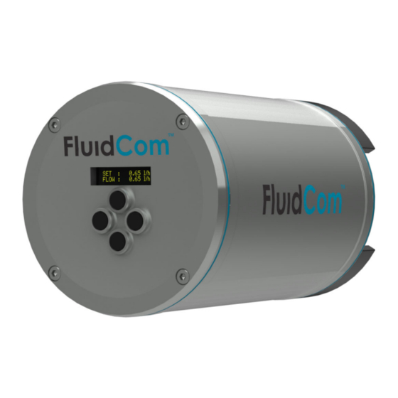
<2. Product overview> Product overview FluidCom S2 chemical injection flow controller includes technology for flow control. Once installed and put into operation, no planned regular maintenance or manual intervention is required. Back Lid Front Lid Display Housing Control Buttons Figure 2.1 FluidCom S2 overview 2.1... -
Page 10: Connection Interfaces
Pressure compensation valve Figure 2.2 FluidCom S2 rear view w/connection interfaces Display Figure 2.3 shows the front view with the display for local operation of FluidCom S2. See section 3.5 for details regarding local operation. Display "Exit" button "Up" button "Down"... -
Page 11: Operation
The operational instructions given in the Ex Instruction Manual (the attached page) must be adhered to at all times. Operation of FluidCom S2 is either remote by HART protocol by a 4-20 mA input loop, or local by use of the display. The HART communication protocol is HART v.7.1. -
Page 12: Volumetric Flow Rate
HART status bit is available on this signal to identify if flow measurement is active. 3.1.3 Controller mode Two controller modes are available in the FluidCom S2 system: • “Auto mode” is the mode intended for normal operation. In this mode, the control system automatically regulates the flow according to the set flow. -
Page 13: System State
<3. Operation> 3.1.4 System state This variable represents the state of the control system. This is also the “start” and “stop” control of the system. The system will be in one of the following states: • “Stopped” – No regulation (no heater power), and consequently the valve is closed. •... -
Page 14: Fluid
FluidCom S2 should only be used with the fluid(s) which calibration data has not been stored in IMPORTANT If FluidCom S2 is intended to be used with a fluid which calibration data is not stored in it, calibration data of that fluid must be loaded into the FluidCom S2 beforehand. Please contact customer service. -
Page 15: Remote Operation By Hart
Remote operation by HART FluidCom S2 comprises a 4-20 mA output loop interface with HART v.7.1 communication protocol. The HART device variables made available for remote operation of FluidCom S2 are presented in section 3.3.1. • The regulation mode must be in auto mode for the use of HART protocol. Charging of regulation mode is not possible by HART commands. -
Page 16: Hart Device Variables
3.3.2 Multidrop FluidCom S2 can be configured for multidrop communication by HART protocol. Maximum number of FluidCom S2 which can be connected to multidrop is eight units a loop. For information regarding HART polling addresses, see section 7.3.2. 3.3.3 Protocol conversion Both point-to-point configuration and multidrop configuration, FluidCom S2 can be operated by other communication protocols (e.g. -
Page 17: Local Operation
<3. Operation> 3.4 Analog input (4-20 mA) for remote flow set FluidCom S2 comprises a separate 4-20 mA AI control loop interface in addition to the HART control loop. This is a separate connection and provides an operation for analog remote setting. See more details in section 4.8.4.3 IMPORTANT In this configuration the analog flow set will be performed from a remote location. -
Page 18: Display Main Menu Flowchart
<3. Operation> 3.5.1 Display main menu flowchart Figure 3.2 Display main menu flowchart IM 23C01B01-01EN... -
Page 19: Display Service Menu Flowchart
<3. Operation> 3.5.2 Display service menu flowchart Figure 3.3 Display service menu flowchart IM 23C01B01-01EN... -
Page 20: Display Operations
3-10 <3. Operation> 3.5.3 Display operations 3.5.3.1 Start and stop system From “system state” view: (to open for changing the system state) (to select “start”) DOWN (to select “stop”) (to confirm the system state) 3.5.3.2 Set flow rate From auto mode default view: (to open for adjusting the set flow) UP/DOWN (to adjust set flow;... - Page 21 3-11 <3. Operation> From “fluid selection” view: (to open for selecting on which fluid to change parameters) UP/DOWN (to change to applicable fluid) (to continue to “correction factor” view) From “correction factor” view: UP/DOWN (to adjust the correction factor; > 1.00 flow decrease; < 1.00 flow increase) (to continue to “specific gravity”...
- Page 22 3-12 <3. Operation> 3.5.3.6 Change regulation mode NOTE To change regulation mode, the system state must be “stopped.” If required to stop the system, see section 3.5.3.1. From “regulation mode” view: (to open for changing the regulation mode) (to select “auto”) DOWN (to select “manual”) (to confirm the regulation mode)
- Page 23 3-13 <3. Operation> LINK STATUS Communication status with main board. OFFLINE ONLINE SYS.RESET Soft power recycles. DIAGNOSTIC Event counters. A = No. of power fault detections (0 W) leading to a system reset. B = No. of system state “warning” detections. C = No.
-
Page 24: Hart Field Communicator
Device Description. FWDCOM CONT EXIT Figure 3.4 Device selection warning message Figure 3.5 shows the main menu for FluidCom S2. Select “1 Overview” to enter the device variables overview page. FluidCom:FLUIDCOM Online 1 Overview 2 Configure 3 Service Tools SAVE Figure 3.5... - Page 25 3-15 <3. Operation> Figure 3.6 shows the overview of all FluidCom S2 device variables made available for HART protocol (ref. section 3.3.1). To change flow setting, select “7 Flow Setting”. FluidCom:FLUIDCOM Overview 1 Flow Reading 0.600 L/h 2 PV Loop current 4.160 mA...
-
Page 26: Installation
FluidCom S2 can only be installed in areas compliant with the FluidCom S2 Ex protection. Consider the following conditions for the installation site: • Verify the FluidCom S2 is installed in areas compliant to the requirements given in the Ex Instruction Manual (the attached page). -
Page 27: Tubing Connection
Bounding cable cross-sectional area shall be minimum 6 mm External earth ground point is located at the rear end of the FluidCom S2 unit (ref. section 2.2). A cable lug must be used on the bounding cable. Bounding cable must have a minimum 6 mm cross-sectional area. -
Page 28: Power Distribution Boards
The terminal cover must be closed properly prior to energizing and power up FluidCom S2. Follow the guidelines given in the Ex Instruction Manual (the attached page) regarding electrical wiring. The FluidCom S2 4-20 mA wiring can be done in various ways depending on the type of communication. See section 4.8.4. IM 23C01B01-01EN... -
Page 29: Cable Glands
<4. Installation> 4.8.1 Cable glands FluidCom S2 is delivered without cable glands. The following requirements are applicable for the cable glands to be mounted: • ATEX and IECEx certified, not compromising the FluidCom S2 Ex protection. • Ingress protection minimum IP66. -
Page 30: Wiring Of Power Cable
Use an armoured power supply cable. IMPORTANT The FluidCom S2 power supply must include an residual current device with a tripping current < 100 mA and a tripping time < 100 ms. The general guidelines for wiring of the power supply are: •... -
Page 31: Wiring Of Signal/Control Cable
Terminal no. 9 and 10 shall not be used as protective earth. FluidCom S2 can be configured both as a single-point-to-point unit and a multidrop unit. Section 4.8.4.1 to 4.8.4.6 presents an overview of how to wire the different configurations. - Page 32 <4. Installation> 4.8.4.1 Single-point-to-point operation by HART Figure 4.4 shows the wiring for the FluidCom S2 configuration providing single-point-to-point operation by HART protocol. NOTE FluidCom S2 is “passive” so the control loop must be powered from CCR. output output input input Figure 4.4...
- Page 33 The set flow is always shown in the FluidCom S2 display. NOTE FluidCom S2 is “passive” so the control loop must be powered from CCR. NOTE Analog outputs (AO) on CCR side (PLC / RIO) must have separated channels. If AO cards don`t have separated channels, isolators must be installed.
- Page 34 <4. Installation> 4.8.4.4 Multidrop operation by HART Figure 4.7 shows the wiring for the FluidCom S2 configuration providing multidrop operation by HART protocol. The maximum number of FluidCom S2 units per control loop is eight. Information about HART polling addresses is found in section 5.3.2.
- Page 35 <4. Installation> 4.8.4.5 Multidrop operation by conversion of HART Figure 4.8 shows the wiring for the FluidCom S2 configuration providing multidrop operation by a bidirectional conversion of the HART protocol signals to another type of communication protocol. The maximum number of FluidCom S2 units per control loop is eight. Information about HART polling addresses is found in section 5.3.2.
- Page 36 4.8.4.6 Multidrop operation by wireless HART Figure 4.9 shows the wiring for the FluidCom S2 configuration providing multidrop operation by wireless HART. The maximum number of FluidCom S2 units per wireless HART antenna is eight. Information about HART polling addresses is found in section 5.3.2.
-
Page 37: Hart Communicator
See section 5.3.1 for information regarding DD for the HART Field Communicator. CAUTION FluidCom S2 control loop is non-is. keep awareness to this when e.g. using HART Field communicator. Figure 4.10... -
Page 38: Commissioning
Recommended 50 micron. IMPORTANT FluidCom S2 must not be exposed to system hydrostatic test if this exceeds 345 bar. Such testing may interrupt the calibration of the unit. FluidCom S2 has been separately hydrostatic tested to 517 bar pressure prior to factory calibration. -
Page 39: Start-Up And System Check
3) If relevant, perform AI CALIB. according to section 3.5.2.9. WARNING Maximum working pressure is 345 bar (5000 psi). 4) Power up FluidCom S2 by applying the electrical power supply. The local display verifies that the unit is powered. NOTE The default system state from factory is “stopped”... -
Page 40: Hart Commissioning
5.3.1 Device Descriptor (DD) FluidCom S2 is delivered with two of Device Descriptor (DD) files; one for Emerson AMS (and other DD enabled host computer software), and one for Emerson Field Communicator (and other field communicators). These files must be installed in the relevant computers/devices to establish the control interface for FluidCom S2. -
Page 41: Maintenance And Repair
IMPORTANT For longer shutdown of injection where chemical can change properties, coagulate or crystallize, action must be taken to purify FluidCom S2 for chemical. This is necessary to ensure full functionality of FluidCom S2 at start-up after injection stop/shutdown. NOTE For maintenance or repair, contact manufacturer or customer service for support. -
Page 42: Troubleshooting
<7. Troubleshooting> Troubleshooting NOTE Use customer service for any type of support needed regarding FluidCom S2. IM 23C01B01-01EN... -
Page 43: Decommissioning / Changing Fluids
Perform the shutdown of FluidCom S2 according to the following procedure: 1) Stop the FluidCom S2 control system (ref. section 3.5.2.1). 2) Shutdown FluidCom S2 by cutting the electrical power supply of 230 - 240 V AC 50/60 Hz. 3) Bleed off trapped pressure as required. -
Page 44: Removal
4) Disconnect the piping from the bulkhead connectors. 5) Remove the FluidCom S2 from the installation panel. 6) Ensure FluidCom S2 is handled with care and being prepared for storage or shipment with proper means for protection. 7) Attach safety data sheet for latest chemical used with FluidCom S2. -
Page 45: Dismantling And Disposal
WARNING Use of fluids that are a health hazard may result in caustic burns or poisoning. 1. When removing FluidCom S2, avoid touching the fluid and breathing gas residues left in the unit. 2. Wear protective clothing/equipment and breathing mask as prescribed in chemical SDS. -
Page 46: Transport And Storage
10-1 <10. Transport and storage> Transport and storage 10.1 Lifting and carrying The weight of FluidCom is 17.5 kg. FluidCom does not have a handle or grip. Therefore, when lifting or carrying it, use anti-slip gloves to secure your grip as much as possible. 10.2 Transport Follow the precautions below when transporting FluidCom:... -
Page 47: Appendix A - Ga Drawing
AppA-1 <APPENDIX A – GA DRAWING> APPENDIX A – GA DRAWING IM 23C01B01-01EN... -
Page 48: Appendix B - Ex Instruction Manual
MARKING meet national and international standards. All FluidCom S2 units have a marking plate located This equipment must be installed, operated on the rear end with the following information. and maintained according to the following instructions. - Page 49 INSTALLATION Pipe connection: Make sure the inlet and outlet pipes are correctly The FluidCom S2 can be installed in areas with the connected, and that the connected piping system following conditions: do not exert excessive forces on the FluidCom S2.
- Page 50 Cleaning of outside surfaces of enclosure is allowed. Use a non-aggressive cleaning agent and respect the IP rating of the unit. SAFETY The FluidCom S2 must be installed, operated and maintained according to the instructions given in this instruction document. IM 23C01B01-01EN...
-
Page 51: Appendix C - Eu-Type Examination Certificate
AppC-1 <APPENDIX C – EU-TYPE EXAMINATION CERTIFICATE> APPENDIX C – EU-TYPE EXAMINATION CERTIFICATE Blank IM 23C01B01-01EN... -
Page 52: Appendix D - Eu Declaration Of Conformity
AppD-1 <APPENDIX D – EU DECLARATION OF CONFORMITY> APPENDIX D – EU DECLARATION OF CONFORMITY Blank IM 23C01B01-01EN... -
Page 53: Appendix E - Certificate Of Conformity
AppE-1 <APPENDIX E – CERTIFICATE OF CONFORMITY> APPENDIX E – CERTIFICATE OF CONFORMITY Blank IM 23C01B01-01EN... -
Page 54: Revision Information
Revision Information Title : Chemical Injection Flow Controller FluidCom-S2 Manual No. : IM 23C01B01-01E Edition Date Page Revised item May 2021 ― New publication IM 23C01B01-01EN... - Page 55 Phone: (65)-6241-9933 Yokogawa India Ltd. Plot No.96, Electronic City Complex, Hosur Road, Bangalore - 560 100, India Yokogawa Middle East & Africa B.S.C.(c) Phone: (91)-80-4158-6000 P.O. Box 10070, Manama, Building 577, Road 2516, Busaiteen 225, Muharraq, Kingdom of Bahrain Phone: (973)-17358100 Yokogawa Australia Pty.
Need help?
Do you have a question about the FluidCom S2 and is the answer not in the manual?
Questions and answers