
Subscribe to Our Youtube Channel
Related Manuals for YOKOGAWA Vitesse FA-M3V


Summary of Contents for YOKOGAWA Vitesse FA-M3V
- Page 1 User’s Manual Hardware Manual IM 34M06C11-01E IM 34M06C11-01E 36th Edition Yokogawa Electric Corporation...
- Page 2 Blank Page...
-
Page 3: Applicable Product
The document number for this manual is given below. Refer to the document number in all communications, including when purchasing additional copies of this manual. Document No.: IM 34M06C11-01E IM 34M06C11-01E 36th Edition : Feb.28, 2019-00 All Rights Reserved Copyright © 1992, Yokogawa Electric Corporation... -
Page 4: Precautions
- Every effort has been made to ensure accuracy in the preparation of this manual. However, should any errors or omissions come to the attention of the user, please contact the nearest Yokogawa Electric representative or sales office. Safety Symbols - ”Handle with care.”... - Page 5 WARRANTY that is provided separately. - Yokogawa Electric assumes no liability to any party for any loss or damage, direct or indirect, caused by the use or any unpredictable defect of the product.
- Page 6 Software Supplied by the Company - Yokogawa Electric makes no other warranties expressed or implied except as provided in its warranty clause for software supplied by the company. - Use the software with one computer only. You must purchase another copy of the software for use with each additional computer.
- Page 7 General Requirements for Using the FA-M3 / e-RT3 Controller Set the product in a location that fulfills the following requirements: - INDOOR USE ONLY - This product is an open equipment. The product must be installed in a metallic panel enclosure with an impact rating IK08 or more.
- Page 8 Configure and route cables with noise control considerations: - Perform installation and wiring that segregates system parts that may likely become noise sources and system parts that are susceptible to noise. Segregation can be achieved by measures such as segregating by distance, installing a filter or segregating the grounding system.
- Page 9 - Refer to “A3.5.4 Grounding Procedure” in the “Hardware Manual” for attaching the grounding wiring. Authorized Representative: - The Authorized Representative for this product in the EEA is: Yokogawa Europe B. V. Euroweg 2, 3825 HD Amersfoort, The Netherlands IM 34M06C11-01E...
- Page 10 viii General Requirements for Using the FA-M3 Slave Units (TAH Series) C onnect YHLS cable to SHIELD terminal: - Connect the DRAIN line of the YHLS cable to the SHIELD terminal of the YHLS master module securely. Failing to do so may affect the performance of the YHLS system.
- Page 11 With reference to the equipment types in the WEEE directive, this product is classified as a “Monitoring and Control instruments”. When disposing of products in the EU, contact your local Yokogawa Europe B. V. office. Do not dispose of this product in domestic household waste.
-
Page 12: Introduction
Introduction Overview of the Manual This manual explains the configuration, specifications, compatible specification, and installation of the Range-Free Multi-controller FA-M3. It also discusses the individual specifications of power supply modules, base modules, I/O modules, cables and terminal block units. ... -
Page 13: Copyrights And Trademarks
Copyrights The copyright of the programs and online manuals contained in the software medium of the Software Product shall remain in YOKOGAWA. You are allowed to print the required pages of the online manuals for the purposes of using or operating the Product; however, reprinting or reproducing the entire document is strictly prohibited by the Copyright Law. - Page 14 Blank Page...
-
Page 15: Table Of Contents
Hardware Manual IM 34M06C11-01E 36th Edition CONTENTS Applicable Product ..................i Precautions ....................ii Introduction ....................x Copyrights and Trademarks ..............xi Part A Standard Version A1. System Configuration ..............A1-1 A1.1 System Configuration ................A1-1 Basic Configuration ................A1-1 ... - Page 16 A2.4 Base Modules ..................A2-23 A2.5 I/O Modules ..................A2-24 Components and Their Functions ............ A2-24 External Dimensions ................ A2-24 Isolation Methods ................A2-25 Terminal Arrangement ..............A2-25 External Connection ................ A2-25 (1) F3XH04-3N High-speed Input Module .......... A2-26 ...
- Page 17 A2.7 Cables ....................A2-98 (1) Cables for Programming Tool ............A2-98 KM11-2N (for PC9801 (NEC)) ..........A2-98 KM11-2T, KM11-3T, KM11-4T (for DOS/V (IBM PC/AT Compatibles)) ........A2-99 KM13-1S (USB-serial Converter) ..........A2-99 (2) CPU Port/D-sub 9-pin Adapter Cable ......... A2-100 ...
- Page 18 A3.3.6 Measures against Power Failure ........... A3-16 A3.4 Noise Control Considerations ............A3-20 A3.5 Wiring the Power Supply Module ............A3-22 A3.5.1 Re-checking Specifications ........... A3-22 A3.5.2 Wiring Materials ..............A3-22 A3.5.3 Power Supply Wiring ............. A3-23 A3.5.4 Grounding Procedure ............A3-25 A3.6 Wiring I/O Modules ................
- Page 19 Part B FA-M3 Value (F3SC21-1N) B1. System Configuration ..............B1-1 B1.1 System Configuration ................B1-1 B1.2 Restrictions on Module Installation............. B1-3 B1.2.1 Restrictions on Module Location ..........B1-3 B1.2.2 Restrictions due to Current Consumption ....... B1-3 B1.3 Peripheral Tools Supporting the Program Development of FA-M3 .. B1-4 B2.
- Page 20 Blank Page...
-
Page 21: Part A Standard Version
TOC A-1 Hardware Manual Part A Standard Version IM 34M06C11-01E 36th Edition IM 34M06C11-01E 36th Edition : Feb.28, 2019-00... - Page 22 Blank Page...
-
Page 23: A1. System Configuration
A1-1 System Configuration A1.1 System Configuration Basic Configuration The basic configuration of FA-M3 is a unit. A unit is a system with the minimum configuration consisting of the following modules. Install these modules on the base module to compose the unit. Table A1.1 Modules (Components) of a Unit Module Description... -
Page 24: Slot Number
A1-2 Slot Number A slot number identifies a slot of a base module in which a CPU module, an I/O module or some other module can be installed. A slot number is a 3-digit integer with the first digit representing a unit number. The unit number of the main unit is 0. Slot number Identifies a slot position starting next to a power supply module and ending at the right end of the base module: 01-16... -
Page 25: Example Of Increasing The Number Of I/O Points Using Fiber-Optic Fa-Bus Type 2 Modules
A1-3 Example of Increasing the Number of I/O Points Using Fiber-optic FA-bus Type 2 Modules You can install fiber-optic FA-bus type 2 modules in both main and subunits and connect them with fiber-optic cables. This enables distributed arrangement of remote I/O points, increase in the number of I/O points, and control of I/O modules via high-speed, noise- immune communication. - Page 26 A1-4 Note ■ Example of increasing the number of I/O points using FA-bus type 2 modules As with fiber-optic FA-bus type 2 modules, the number of I/O points can be increased using FA-bus type 2 modules. FA-bus type 2 modules use shielded twisted-pair cables for the connection between subunits.
-
Page 27: A1.2 Restrictions On Module Installation
A1-5 A1.2 Restrictions on Module Installation A1.2.1 Restrictions on Module Location - A Power supply module must be installed in the most left side slot. - A CPU module installed in slot 1 serves as the main CPU module. - CPU modules installed in slots 2 to 4 serve as the add-on CPU modules. - I/O modules may also be installed in slots 2 to 4. -
Page 28: A1.2.2 Restrictions On Cpu Module Installation
A1-6 A1.2.2 Restrictions on CPU Module Installation A maximum of four CPU modules can be installed in slots 1 to 4. Table A1.2 Combinations of Main CPU Modules with Add-on CPU Modules Add-on CPU Module Model F3SP21-0N ✓ ✓ ✓ ✓ ✓ ✓ ✓ ✓ ✓ ✓ ✓ ✓... -
Page 29: A1.2.3 Restrictions On I/O Module Installation
A1-7 A1.2.3 Restrictions on I/O Module Installation Table A1.3 shows the types of modules that each CPU module can access directly, as well as the maximum number of modules of each type that can be installed at the same time. The maximum number referred to here means a limit to the quantity of modules when a multiple of the same I/O module is installed. - Page 30 A1-8 Table A1.3 Modules that Each CPU can Access Directly and the Maximum Number that can be Installed (2/2) BASIC CPU Sequence CPU Module Name Model DeviceNet interface module F3LD01-0N CAN2.0B interface module F3LD21-0N F3LE01-T F3LE01-5T Ethernet interface module F3LE11-T F3LE12-T F3LH0-0N YHLS master module...
-
Page 31: A1.2.4 Restrictions Due To Current Consumption
A1-9 A1.2.4 Restrictions due to Current Consumption Design your system making sure that the total sum of current consumed by modules in each unit does not exceed the capacity of the power supply module. For more information, see Section A2.9, "Module Current Consumption Tables" IM 34M06C11-01E 36th Edition : Feb.28, 2019-00... -
Page 32: Peripheral Tools Supporting The Program Development Of The Fa-M3
A1-10 A1.3 Peripheral Tools Supporting the Program Development of the FA-M3 You can conveniently create and debug your programs on your personal computer. - FA-M3 Programming Tool WideField3 - FA-M3 ToolBox FA-M3 - BASIC Programming Tool M3 for Windows CD-ROM Ethernet, cable for programming tools (RS-232-C), Personal USB or FL-net... -
Page 33: A2. Specifications And Configuration
A2-1 Specifications and Configuration A2.1 Specifications Common Specifications Item Specifications Operating : 0 to 55°C Surrounding air temperature range Storage -20°C to 75°C Operating : 10 to 90% RH (non-condensing) Surrounding humidity range Storage 10 to 90% RH (non-condensing) Surrounding atmosphere Must be free of corrosive gases, flammable gases or heavy dust. -
Page 34: Power Supply Specifications
A2-2 Power Supply Specifications Specifications Item F3PU10-0N F3PU20-0N F3PU30-0N F3PU16-0N F3PU26-0N F3PU36-0N F3PU10-0S F3PU20-0S F3PU30-0S F3PU16-0S F3PU26-0S F3PU36-0S Supply voltage range 100 to 240 V AC, single phase 50/60 Hz 24 V DC Range of supply voltage change 85 to 264 V AC 50/60Hz±3Hz 15.6 to 31.2 V DC Power consumption 35 VA... -
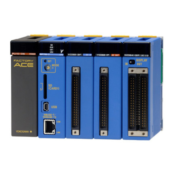
Page 35: A2.2 Fa-M3 Controller Configuration
A2-3 A2.2 FA-M3 Controller Configuration A2.2.1 Components Module Names Base module Power supply module CPU module I/O modules and special modules FA020201.VSD Figure A2.1 FA-M3 Controller FA-M3 Components Modules indicated by the triangle symbol () in the tables below are no longer available. ... - Page 36 A2-4 CPU Modules Module Description Model Specifications 10K ladder steps, 0.18 to 0.36 s execution time for basic instructions F3SP21-0N 20K ladder steps, 0.12 to 0.24 s execution time for basic instructions F3SP25-2N 100K ladder steps, 0.09 to 0.18 s execution time for basic instructions ...
- Page 37 A2-5 ROM Packs Module Description Model Specifications 5K ladder steps RK10-0N (F3SP21) 20K ladder steps; 120KB for BASIC RK30-0N (F3SP21/25/35, F3BP20) 100K ladder steps; 510KB for BASIC RK50-0N (F3SP21/25/35, F3BP30) 56K ladder steps ROM pack RK33-0N (F3SP21/22/25/28/35/38/53/58) 100K ladder steps; 510KB for BASIC RK53-0N (F3SP21/25/35, F3BP30) 120K ladder steps...
- Page 38 A2-6 I/O Modules For detailed I/O module specifications, see A2.5, "I/O Modules." Module Description Model Specifications 24 V DC high-speed input points with pulse-capture feature, 4 points High-speed input module F3XH04-3N 100 to 120 V AC, 8 points F3XA08-1N 200 to 240 V AC, 8 points AC input module F3XA08-2N...
- Page 39 A2-7 Analog I/O and Temperature Control Modules Module Description Model Specifications F3AD04-0N 0 to 5 V DC /1 to 5 V DC /-10 to 10 V DC, 4 points, 12-bit ADC F3AD04-0R 0 to 5 V DC /1 to 5 V DC /-10 to 10 V DC, 4 points, 16-bit ADC 0 to 5 V / 1 to 5 V / -10 to 10 V / 0 to 10 V DC F3AD04-5R 4 differential inputs, 16-bit A/D conversion...
- Page 40 A2-8 Communication Modules Module Description Model Specifications 1 AS-interface V2.1 port ASi Master module F3LA01-0N PROFIBUS-DP Interface 1 PROFIBUS-DP port; 12Mbps max. F3LB01-0N module 1 RS-232-C port; 115.2 kbps max. F3LC11-1F F3LC11-1N 1 RS-232-C port; 19200 bps max. Personal computer 1 RS-422-A/RS-485 port;...
- Page 41 A2-9 Counter and Positioning Modules Module Description Model Specifications 100 kpps, 1 channel, 32 bits F3XP01-0H High-speed counter 100 kpps, 2 channels, 32 bits module F3XP02-0H 20 kHz, 4 channels, 24 V input, 16 bits F3XS04-3N Pulse input module 20 kHz, 4 channels, 12 V input, 16 bits F3XS04-4N Positioning module...
- Page 42 A2-10 Cables For detailed cable specifications, see A2.7, "Cables." Style Cable Description Model Specifications Code D-sub, 25-pin, male, 3m long KM11-2N Cable for programming D-sub, 9-pin, female, 3 m long tools KM11-2T D-sub, 9-pin, female, 5 m long KM11-3T D-sub, 9-pin, female, 10 m long ...
- Page 43 A2-11 For detailed cable specifications, see A2.7, "Cables." Style Cable Description Model Specifications Code ― For connection between module and connector terminal block; 0.5 m long KM55-005 Cable for connector ― For connection between module and connector terminal block; 1 m long KM55-010 terminal blocks For connection between module and connector terminal block;...
- Page 44 A2-12 Terminal Block Name Model Specifications 40 points; voltage rating: 5 to 24 V DC *1*2 Terminal block unit TA40-0N Connector terminal block 40 points (M3.5 screw) TA50-0N Connector terminal block 40 points (M3 screw) ▲ TA50-1N *1*2 Connector terminal block Connector terminal block 40 points (M3 screw) TA50-2N Connector terminal block 40 points (Europe terminal type)
-
Page 45: A2.3 Power Supply Modules
A2-13 A2.3 Power Supply Modules F3PU10-0N/F3PU10-0S/F3PU20-0N/F3PU20-0S Power Supply Modules Specifications Specifications Item F3PU10-0N/ F3PU10-0S * F3PU20-0N/ F3PU20-0S * Supply voltage range 100 to 240 V AC, single phase 50/60 Hz Range of supply voltage 85 to 264 V AC 50/60 Hz±3 Hz change Power consumption 35VA... - Page 46 A2-14 Note LG terminal has a half potential of the input power supply voltage when LG terminal isn’t connected to earth appropriately. Terminal dimensions F3PU10-0N / F3PU20-0N F3PU10-0S / F3PU20-0S M3.5 7.1mm 7.1mm 8.2mm 8.2mm FA020304.VSD Adaptable crimp-on terminal Compatible Modules and Crimping Torque Vendor...
- Page 47 A2-15 Note Power supply circuit which is connected to FAIL signal contact output terminal must be SELV and limited-energy circuit separated by reinforced insulation or double insulation from hazardous voltage. IM 34M06C11-01E 36th Edition : Feb.28, 2019-00...
-
Page 48: F3Pu30-0N/F3Pu30-0S Power Supply Modules
A2-16 F3PU30-0N/F3PU30-0S Power Supply Modules Specifications Specifications Item F3PU30-0N/F3PU30-0S Supply voltage 100 to 240V AC, single phase, 50/60 Hz Range of supply voltage change 85 to 264 V AC, 50/60 Hz ±3Hz Power consumption 100 VA Inrush current 20 A max. (120V AC, Ta=25°C), 45A max. (240V AC, Ta=25°C) Time-lag fuse Fuse (Built into the L and N terminals and cannot be replaced.) - Page 49 A2-17 Terminal dimensions F3PU30-0N F3PU30-0S M3.5 7.1mm 7.1mm 8.2mm 8.2mm FA020306.VSD Adaptable crimp-on terminals Crimping Torque Vendor Model Compatible Conductor F3PU30-0N F3PU30-0S Japan Solderless V1.25-M3 May not be Terminal Mfg Co., Ltd. AWG22 to 18 used Nippon Tanshi Co., Ltd. RAV1.25-3.5 (0.33 to 0.82 mm (Copper wire)
-
Page 50: F3Pu16-0N/ F3Pu16-0S And F3Pu26-0N/ F3Pu26-0S Power Supply Modules
A2-18 F3PU16-0N/ F3PU16-0S and F3PU26-0N/ F3PU26-0S Power Supply Modules Specifications Specifications Item F3PU16-0N/ F3PU16-0S * F3PU26-0N/ F3PU26-0S * Supply voltage 24 V DC Range of supply voltage change 15.6 to 31.2 V DC Power consumption 15.4W 33.1W Inrush current 20 A max. - Page 51 A2-19 Terminal dimensions F3PU16-0N / F3PU26-0N F3PU16-0S / F3PU26-0S M3.5 7.1mm 7.1mm 8.2mm 8.2mm FA020304.VSD Adaptable crimp-on terminals Crimping Torque Vendor Model Compatible Conductor F3PU16-0N F3PU16-0S F3PU26-0N F3PU26-0S Japan Solderless V1.25-M3 May not be Terminal Mfg Co., Ltd. AWG22 to 18 used Nippon Tanshi Co., Ltd.
-
Page 52: F3Pu36-0N/F3Pu36-0S Power Supply Module
A2-20 F3PU36-0N/F3PU36-0S Power Supply Module Specifications Specifications Item F3PU36-0N/F3PU36-0S Supply voltage 24 V DC Range of supply voltage 15.6 to 31.2 V DC change Power consumption 46.2 W Inrush current 20 A max. (31.2 V DC, Ta=25°C) Time-lag fuse Fuse (Built into the positive terminal and cannot be replaced.) Rated output voltage... - Page 53 A2-21 Note LG terminal has a half potential of the input power supply voltage when LG terminal isn’t connected to earth appropriately. Terminal dimensions F3PU36-0N F3PU36-0S M3.5 7.1mm 7.1mm 8.2mm 8.2mm FA020306.VSD Adaptable crimp-on terminals Crimping Torque Vendor Model Compatible Conductor F3PU36-0N...
- Page 54 A2-22 Note Power supply circuit which is connected to 24VDC power supply terminal and FAIL signal contact output terminal must be SELV and limited-energy circuit separated by reinforced insulation or double insulation from hazardous voltage. IM 34M06C11-01E 36th Edition : Feb.28, 2019-00...
-
Page 55: A2.4 Base Modules
A2-23 A2.4 Base Modules There are six types of base modules: 4-, 6-, 5-, 9-, 13-, and 16-slot modules. Select an appropriate type of module according to your application needs. Model Number of Slots Number of I/O Slots Weight F3BU04-0N 150 g F3BU06-0N 210 g... -
Page 56: A2.5 I/O Modules
A2-24 A2.5 I/O Modules Components and Their Functions Terminal Block Type Connector Type • 10-point terminal block • 18-point terminal block Input indicaton LED: Input indication LED: Indicate the on or off Indicate the on or off XD16-... -
Page 57: Isolation Methods
A2-25 Isolation Methods The internal circuit is isolated from the field using one of the following methods: Photocoupler isolation : Withstands 1500 V AC for 1 minute. Mechanical isolation : Withstands 1500 V AC for 1 minute. Transformer isolation : Withstands 500 V AC for 1 minute. -
Page 58: F3Xh04-3N High-Speed Input Module
A2-26 F3XH04-3N High-speed Input Module Item Specifications Item Specifications Input type DC voltage Number of points Pulse-capture Selection Selected by DIP switches Common line type 4 independent points features Photo-coupler Insulation method insulation 1500 V AC for one minute between the group of terminals for Withstanding voltage external connection... -
Page 59: Setting Up The Pulse-Capture And Interrupt Functions
A2-27 Setting up the Pulse-capture and Interrupt Functions The F3XH04-3N allows you to enable the pulse-capture or interrupt function by setting its internal DIP switch (DIP SW). (1) Hardware Setup Remove the side cover and select the desired function with internal DIP SW 1. The pulse-capture function is selected as default at the factory. - Page 60 A2-28 - Interrupt function The interrupt function may be used from either a ladder or BASIC program. Inputs 1-4 correspond to terminal numbers 1-4. (1) Interrupt processing in a ladder program When using the interrupt function as an interrupt input, make an “I/O interrupt definition”...
- Page 61 A2-29 (4) Functional Description Pulse-capture Function The pulse-capture function is designed to reliably catch input pulses shorter than the scan time. As the CPU module usually reads the data of I/O modules during I/O refresh cycle, when a normal input module is used, the CPU may fail to read input pulses shorter than the scan time.
- Page 62 A2-30 - Interrupt Function If the interrupt function is selected, the F3XH04-3N module continues to hold its input on for the duration of 512 µs once it detects an off-to-on transition in the input. The interrupt program therefore may not be executed if an input pulse shorter than 512 µs is used as the interrupt signal.
-
Page 63: F3Xa08-1N/F3Xa08-2N Ac Input Modules
A2-31 F3XA08-1N/F3XA08-2N AC Input Modules Specifications Item F3XA08-1N F3XA08-2N Input type AC voltage Number of points Common line type 8 points/common line Isolation method Photocoupler insulation 1500 V AC for one minute between the group of terminals for Withstanding voltage external connection and the internal circuit 100 to 120 V AC 200 to 240 V AC... - Page 64 A2-32 Front View F3XA08-1N F3XA08-2N XA08-1N AC IN XA08-2N AC IN FA020511.VSD Internal Circuit Configuration External Connection Diagram Interface FA020512.VSD FA020513.VSD Note: Viewed from the front side of the module. IM 34M06C11-01E 36th Edition : Feb.28, 2019-00...
-
Page 65: F3Xa16-1N Ac Input Module
A2-33 F3XA16-1N AC Input Module Item Specifications Item Specifications Operating Input type AC voltage 80 V AC min., 5 mA min. voltage Number of points 40 V AC max., 1 mA min. /current 15 ms max. or 30 ms, Common line type 8 points/common line OFF→ON Response... -
Page 66: F3Xc08-0N No-Voltage Contact Input Module
A2-34 F3XC08-0N No-voltage Contact Input Module Item Specifications Item Specifications Input type No-voltage contact 2.0 ms max. or 17 ms, OFF→ON selectable Number of points Response time Common line type 8 points/common line 2.0 ms max. or 17 ms, ON→OFF selectable Isolation method Transformer insulation... -
Page 67: F3Xc08-0C No-Voltage Contact Input Module (Independent Commons)
A2-35 F3XC08-0C No-voltage Contact Input Module (independent commons) Item Specifications Item Specifications Input sampling time can Input type No-voltage contact be specified for 5 steps: Always (0 μs), 62.5 μs, OFF→ON Number of points 250 μs, 1 ms, and *3 *4 Response 16 ms. -
Page 68: F3Xd08-6F Dc Input Module
A2-36 F3XD08-6F DC Input Module Item Specifications Item Specifications Input type DC voltage Input sampling time can be Number of points specified for 5 steps: OFF→ON Always (0 μs), 62.5 μs, 250 μs, Common line type 8 points/common line 1 ms, and 16 ms. Isolation method Photocoupler isolation Response... -
Page 69: F3Xd16-3F/F3Xd16-4F/F3Xd16-3H Dc Input Modules
A2-37 F3XD16-3F/F3XD16-4F/F3XD16-3H DC Input Modules Specifications Item F3XD16-3F F3XD16-4F F3XD16-3H DC voltage Input type DC voltage (positive common) Number of points Common line type 8 points/common line Isolation method Photocoupler isolation 1500 V AC for one minute between the group of terminals for external connection and the Withstanding voltage internal circuit Rated input voltage... - Page 70 A2-38 Front View F3XD16-3F F3XD16-4F F3XD16-3H XD16-3F DC IN DC IN DC IN XD16-4F XD16-3H COM1 COM1 COM1 COM2 COM2 COM2 FA020520.VSD Internal Circuit Configuration External Connection Diagram F3XD16-3F, F3XD16-4F F3XD16-3F,F3XD16-4F – Interface – ...
-
Page 71: F3Xd32-3F/F3Xd32-4F/F3Xd32-5F Dc Input Modules
A2-39 F3XD32-3F/F3XD32-4F/F3XD32-5F DC Input Modules Specifications Item F3XD32-3F F3XD32-4F F3XD32-5F Input type DC voltage Number of points Common line type 8 points/common line Isolation method Photocoupler isolation 1500 V AC for one minute between the group of terminals for external connection and the Withstanding voltage internal circuit Rated input voltage... - Page 72 A2-40 Front View F3XD32-3F F3XD32-4F F3XD32-5F XD32-5F DC IN XD32-3F DC IN XD32-4F DC IN FA020523.VSD Internal Circuit Configuration External Connection Diagram COM4 COM2 – Interface – FA020524.VSD COM3 COM1 ...
-
Page 73: F3Xd64-3F/F3Xd64-4F Dc Input Modules
A2-41 F3XD64-3F/F3XD64-4F DC Input Modules Specifications Item F3XD64-3F F3XD64-4F Input type DC voltage Number of points Common line type 8 points/common line Isolation method Photocoupler isolation 1500 V AC for one minute between the group of terminals for Withstanding voltage external connection and the internal circuit Rated input voltage 24 V DC... - Page 74 A2-42 Front View F3XD64-4F F3XD64-3F XD64-3F DC IN XD64-4F DC IN DISPLAY DISPLAY FA020526.VSD Internal Circuit Configuration External Connection Diagram COM4 COM2 COM8 COM6 – Interface – COM3 COM1 COM7 COM5 Display selection FA020527.VSD FA020528.VSD Note: Viewed from the front side of the module. IM 34M06C11-01E 36th Edition : Feb.28, 2019-00...
-
Page 75: F3Xd08-6N Dc Input Module
A2-43 (10) F3XD08-6N DC Input Module Item Specifications Item Specifications Input type DC voltage Number of points 2.0 ms max. or 17 ms, OFF→ON selectable Common line type 8 points/common line Photocoupler Isolation method isolation 1500 V AC for one Response minute between the time... - Page 76 A2-44 Front View Internal Circuit Configuration F3XD08-6N – DC IN XD08-6N Interface – 9 COM FA020530.VSD External Connection Diagram FA020529.VSD FA020531.VSD Note: Viewed from the front side of the module. IM 34M06C11-01E 36th Edition : Feb.28, 2019-00...
-
Page 77: F3Xd16-3N/F3Xd16-4N Dc-Input Modules
A2-45 (11) F3XD16-3N/F3XD16-4N DC-Input Modules Specifications Item F3XD16-3N F3XD16-4N Input type DC voltage Number of points Common line type 8 points/common line Isolation method Photocoupler isolation 1500 V AC for one minute between the group of terminals for Withstanding voltage external connection and the internal circuit Rated input voltage 24 V DC... - Page 78 A2-46 Front View F3XD16-3N F3XD16-4N XD16-3N DC IN DC IN XD16-4N COM1 COM1 COM2 COM2 FA020532.VSD Internal Circuit Configuration External Connection Diagram – – Interface 9 COM COM1 FA020533.VSD COM2 FA020534.VSD Note: Viewed from the front side of the module. IM 34M06C11-01E 36th Edition : Feb.28, 2019-00...
-
Page 79: F3Xd32-3N/F3Xd32-4N/F3Xd32-5N Dc Input Modules
A2-47 (12) F3XD32-3N/F3XD32-4N/F3XD32-5N DC Input Modules Specifications Item F3XD32-3N F3XD32-4N F3XD32-5N Input type DC voltage Number of points Common line type 8 points/common line Isolation method Photocoupler isolation 1500 V AC for one minute between the group of terminals for external connection and Withstanding voltage the internal circuit Rated input voltage... - Page 80 A2-48 Front View F3XD32-3N F3XD32-4N F3XD32-5N XD32-3N DC IN XD32-4N DC IN XD32-5N DC IN FA020535.VSD Internal Circuit Configuration External Connection Diagram COM4 COM2 – -– Interface – – – – FA020536.VSD COM3 COM1 – – – –...
-
Page 81: F3Xd64-3N/F3Xd64-4N Dc Input Modules
A2-49 (13) F3XD64-3N/F3XD64-4N DC Input Modules Specifications Item F3XD64-3N F3XD64-4N Input type DC voltage Number of points Common line type 8 points/common line Isolation method Photocoupler isolation 1500 V AC for one minute between the group of terminals for Withstanding voltage external connection and the internal circuit Rated input voltage 24 V DC... - Page 82 A2-50 Front View F3XD64-4N F3XD64-3N XD64-3N DC IN XD64-4N DC IN DISPLAY DISPLAY FA020538.VSD Internal Circuit Configuration External Connection Diagram COM4 COM2 COM8 COM6 – – – – – – – – – Interface – COM3 COM1 COM7 COM5 Display selector...
-
Page 83: F3Xd64-6M Dc Input Module
A2-51 (14) F3XD64-6M DC Input Module Item Specifications Item Specifications Input type DC voltage OFF→ON 16 ms max. Number of points Common line type 8×8 matrix scan Isolation method Photocoupler isolation 1500 V AC for one minute Response between the group of time Withstanding voltage connectors for external... -
Page 84: F3Yd04-7N Transistor Output Module
A2-52 (15) F3YD04-7N Transistor Output Module Item Specifications Item Specifications ─ Output type Transistor contact Mechanical Service life ─ Number of points Electrical Common line type All points independent Surge protector Zener diode 3.15A time-lag fuse (Built into each type-N Isolation method Photocoupler isolation Fuse... -
Page 85: F3Ya08-2N Triac Output Module
A2-53 (16) F3YA08-2N Triac Output Module Item Specifications Item Specifications ─ Output type Triac contact Mechanical Service life ─ Number of points Electrical Common line type 8 points/common Surge protector CR absorber, varistor 4 A time-lag fuse (Built into Isolation method Photocoupler isolation Fuse the COM terminal and... - Page 86 A2-54 Front View Internal Circuit Configuration F3YA08-2N YA08-2N ACOUT Interface FA020548.VSD External Connection Diagram FA020547.VSD FA020549.VSD Note: Viewed from the front side of the module IM 34M06C11-01E 36th Edition : Feb.28, 2019-00...
-
Page 87: F3Yc08-0C/F3Yc08-0N Relay Output Module
A2-55 (17) F3YC08-0C/F3YC08-0N Relay Output Module Specifications Item F3YC08-0C F3YC08-0N Output type Relay contact Number of points Common line type All points independent 8 points/common Isolation method Mechanical insulation 1500 V AC for one minute between the group of terminals for external connection Withstanding voltage and the internal circuit Rated load... - Page 88 A2-56 CAUTION The relays in the relay output modules are not of hermetically sealed type. Dust or corrosive gases in the installation environment adversely affect the service life of the relays. Relays that are switched on and off in an atmosphere containing silicone gases from silicone-based materials may suffer from poor electrical contact due to SiO (silicon dioxide) formed and deposited on the surfaces of their contacts.
- Page 89 A2-57 Front View Internal Circuit Configuration F3YC08-0C Internal 5V YC08-0C RL OUT Interface FA020551.VSD External Connection Diagram FA020550.VSD Front View FA020552.VSD Note: Viewed from the front side of the module. F3YC08-0N Internal Circuit Configuration Internal 5V YC08-0N RLOUT Interface...
-
Page 90: F3Yd08-6A/F3Yd08-6B Transistor Output Modules
A2-58 (18) F3YD08-6A/F3YD08-6B Transistor Output Modules Specifications Item F3YD08-6A F3YD08-6B Transistor contact Transistor contact Output type (sink type) (source type) Number of points Common line type 8 points/common Isolation method Photocoupler isolation 1500 V AC for one minute between the group of terminals for Withstanding voltage external connection and the internal circuit 12-24 V DC... - Page 91 A2-59 Front View Internal Circuit Configuration F3YD08-6A Interface YD08-6A DCOUT – FA020557.VSD External Connection Diagram 12-24V FA020558.VSD FA020556.VSD Note: Viewed from the front side of the module. Front View Internal Circuit Configuration F3YD08-6B Interface YD08-6B DC OUT –...
-
Page 92: F3Yd08-7A Transistor Output Module
A2-60 (19) F3YD08-7A Transistor Output Module Specifications Item F3YD08-7A Transistor contact Output type (sink type) Number of points Common line type 8 points/common Isolation method Photocoupler isolation 1500 V AC for one minute between the group of terminals Withstanding voltage for external connection and the internal circuit 12-24 V DC Rated load voltage... - Page 93 A2-61 ● Internal Circuit Configuration Front View F3YD08-7A Interface + YD08-7A DCOUT - FA0205571.VSD ● External Connection Diagram 12-24V FA020558.VSD Note: Viewed from the front side of the module. FA0205561.VSD IM 34M06C11-01E 36th Edition : Feb.28, 2019-00...
-
Page 94: F3Yd14-5A/F3Yd14-5B Transistor Output Modules
A2-62 (20) F3YD14-5A/F3YD14-5B Transistor Output Modules Specifications Item F3YD14-5A F3YD14-5B Transistor contact Transistor contact Output type (sink type) (source type) Number of points Common line type 8 points/common, 6 points/common Isolation method Photocoupler isolation 1500 V AC for one minute between the group of terminals for Withstanding voltage external connection and the internal circuit 12-24 V DC... - Page 95 A2-63 Front View Internal Circuit Configuration F3YD14-5A Interface – YD14-5A DC OUT FA020563.VSD External Connection Diagram COM1 COM1 12 |24V COM2 COM2 FA020562.VSD 12 |24V FA020564.VSD Front View Note: Viewed from the front side of the module. ...
-
Page 96: F3Yc16-0N Relay Output Module
A2-64 (21) F3YC16-0N Relay Output Module Item Specifications Item Specifications Output type Relay contact Mechanical 20 million operations or more Service life 100,000 operations or more Number of points Electrical (rated load) Common line type 8 points/common Surge protector None Isolation method Mechanical insulation Fuse... - Page 97 A2-65 Front View Internal Circuit Configuration Internal 5V F3YC16-0N YC16-0N RL OUT Interface FA020569.VSD External Connection Diagram COM1 COM1 COM2 FA020568.VSD COM2 FA020570.VSD Note: Viewed from the front side of the module. IM 34M06C11-01E 36th Edition : Feb.28, 2019-00...
-
Page 98: F3Yd32-1A/F3Yd32-1B Transistor Output Modules
A2-66 (22) F3YD32-1A/F3YD32-1B Transistor Output Modules Specifications Item F3YD32-1A F3YD32-1B Transistor contact Transistor contact Output type (sink type) (source type) Number of points Common line type 8 points/common Isolation method Photocoupler isolation 1500 V AC for one minute between the group of terminals for Withstanding voltage external connection and the internal circuit Rated load voltage... - Page 99 A2-67 Front View Internal Circuit Configuration F3YD32-1A Interface – YD32-1A DC OUT FA020572.VSD External Connection Diagram 12-24V 12-24V COM4 COM2 12-24V 12-24V COM3 COM1 FA020573.VSD FA020571.VSD Note: Viewed from the front side of the module. Internal Circuit Configuration Front View F3YD32-1B...
-
Page 100: F3Yd32-1H Transistor Output Module (For High Speed Output)
A2-68 (23) F3YD32-1H Transistor Output Module (for high speed output) Item Specifications Item Specifications ─ Mechanical Service Transistor contact ─ Output type life Electrical (sink type) Protection Short-circuit Controlled short-circuit current Number of points circuitry Common line type 8 points/common Overheat Output shutdown Isolation method... - Page 101 A2-69 ● Internal Circuit Configuration Front View Voltage F3YD32-1H Regulator 9 COM L Interface Overheat/over- current protector L YD32-1H DC OUT FA020571_2.vsd ● External Connection Diagram 12-24V 12-24V COM4 COM2 12-24V 12-24V COM3 COM1 FA020573.VSD Note: Viewed from the front side of the module. FA020571_3.VSD IM 34M06C11-01E 36th Edition : Feb.28, 2019-00...
-
Page 102: F3Yd32-1P/F3Yd64-1P Transistor Output Modules (With Short-Circuit Protector)
A2-70 (24) F3YD32-1P/F3YD64-1P Transistor Output Modules (with short- circuit protector) Item F3YD32-1P F3YD64-1P Item F3YD32-1P F3YD64-1P Short-circuit Controlled short-circuit current Transistor contact Protection Output type (sink type) circuitry Overheat Output shutdown Number of points Surge protector Active clamp circuit Common line type 8 points/common Fuse None... - Page 103 A2-71 Front View Internal Circuit Configuration Voltage F3YD32-1P Regulator 9 COM Interface YD32-1P DC OUT Overheat/over- current protector FA020571_2.vsd External Connection Diagram F3YD32-1P 12-24V 12-24V COM4 COM2 12-24V 12-24V FA020571_1.VSD COM3 COM1 F3YD64-1P YD64-1P DC OUT DISPLAY FA020573.VSD Note: Viewed from the front side of the module.
-
Page 104: F3Yd32-1R/F3Yd64-1R Transistor Output Modules (With Short-Circuit Protector)
A2-72 (25) F3YD32-1R/F3YD64-1R Transistor Output Modules (with short- circuit protector) Item F3YD32-1R F3YD64-1R Output type Transistor contact (source type) Number of points Common line type 8 points/common Isolation method Photocoupler isolation 1500 V AC for one minute between the group of terminals for external Withstanding voltage connection and the internal circuit Rated load voltage... - Page 105 A2-73 CAUTION Operation of the protection circuitry: - If short-circuit occurs, the ON voltage increases and the short-circuit current is limited within the range 1-3 A. - If the short-circuit condition is removed, normal operation resumes. - If the short-circuit condition persists, the short-circuit current may cause the temperature of the output element to reach approx.
- Page 106 A2-74 Front View Internal Circuit Configuration 9 COM Voltage F3YD32-1R Regulator L Interface YD32-1R DC OUT Overheat/over- current protector L FA020571_4.vsd External Connection Diagram F3YD32-1R COM4 COM2 12 12 11 11 10 10 COM3 COM1 FA020571_3.VSD ...
- Page 107 A2-75 Front View Internal Circuit Configuration 9 COM Voltage F3YD64-1R Regulator Interface YD64-1R DC OUT DISPLAY Overheat/over- current protector FA020571_4.vsd External Connection Diagram F3YD64-1R COM4 COM2 COM8 COM6 + + + + 12 12 12 12 11 11 11 11 10 10 10 10...
-
Page 108: F3Yd32-1T Ttl Output Module
A2-76 (26) F3YD32-1T TTL Output Module Item Specifications Item Specifications Fuse None Transistor contact Output type (TTL output) 4.9 V min. (no load) Off time Number of points Output 3.0 V min. (with 0.4 mA load) voltage 0.4V max. (over entire load Common line type 8 points/common On time... - Page 109 A2-77 Front View Internal Circuit Configuration F3YD32-1T Interface – YD32-1T DC OUT FA020578.VSD External Connection Diagram 20 20 COM 4 COM 2 COM 1 COM 3 FA020577.VSD FA020579.VSD Note: Viewed from the front side of the module. IM 34M06C11-01E 36th Edition : Feb.28, 2019-00...
-
Page 110: F3Yd64-1A Transistor Output Module
A2-78 (27) F3YD64-1A Transistor Output Module Item Specifications Item Specifications ─ Mechanical Transistor contact Output type Service life (sink type) ─ Electrical Number of points Surge protector Zener diode Common line type 8 points/common Fuse None Isolation method Photocoupler isolation Dissipating current 275 mA (5 V DC) 1500 V AC for one... - Page 111 A2-79 Front View Internal Circuit Configuration F3YD64-1A Interface YD64-1A DC OUT – DISPLAY Select Display FA020584.VSD External Connection Diagram 24V 24V 24V 24V COM4 COM8 COM6 COM2 24V 24V 24V 24V COM5 COM3 COM1 COM7 FA020583.VSD...
-
Page 112: F3Yd64-1F Transistor Output Module
A2-80 (28) F3YD64-1F Transistor Output Module Item Specifications Item Specifications ─ Mechanical Transistor contact Output type Service life (sink type) ─ Electrical Number of points Surge protector Zener diode Common line type 8 points/common Fuse None Isolation method Photocoupler isolation Dissipating current 275 mA (5 V DC) 1500 V AC for one... - Page 113 A2-81 Front View Internal Circuit Configuration F3YD64-1F Interface YD64-1F DC OUT DISPLAY Display selection FA020581.VSD External Connection Diagram 12-24V 12-24V 12-24V 12-24V COM4 COM2 COM8 COM6 + + + + 12-24V 12-24V 12-24V 12-24V FA020580.VSD COM5 COM3 COM1 COM7 +...
-
Page 114: F3Yd64-1M Transistor Output Module
A2-82 (29) F3YD64-1M Transistor Output Module Item Specifications Item Specifications ─ Mechanical Transistor contact Output type Service life (matrix scan) ─ Electrical Number of points Surge protector Zener diode Common line type 8×8 matrix Fuse None Isolation method Photocoupler isolation Dissipating current 125 mA (5 V DC) 1500 V AC for one... - Page 115 A2-83 Front View Internal Circuit Configuration F3YD64-1M 12 / 24V DC OUT 8 • • • • OUT 2 Interface YD64-1M DC OUT OUT 1 DISPLAY DATA 8 DATA 7 • • • DATA 1 Display selector FA020587.VSD ...
-
Page 116: F3Wd64-3P/F3Wd64-4P Input/Output Modules (With Short-Circuit Protector)
A2-84 (30) F3WD64-3P/F3WD64-4P Input/Output Modules (with short-circuit protector) Input Block Item F3WD64-3P F3WD64-4P Input type DC voltage Number of points 32 (terminal Nos. 01 - 32) Common line type 8 points/common Isolation method Photocoupler isolation 1500 V AC for one minute between the group of terminals for external Withstanding voltage connection and the internal circuit Rated input voltage... - Page 117 A2-85 If an inductive load, such as a relay, is to be connected, a surge protector is also required on the load side. Connect a surge protector or a diode across the load nearby so that the module output terminal voltage will not exceed the specified operating load voltage range.
- Page 118 A2-86 Front View F3WD64-3P F3WD64-4P WD64-4P DC I/O WD64-3P DC I/O DISPLAY DISPLAY FA020589_2.VSD Internal Circuit Configuration Voltage Regulator - + Overheat/over- current protector + - - + Display selector FA020590_2.VSD IM 34M06C11-01E 36th Edition : Feb.28, 2019-00...
- Page 119 A2-87 External Connection Diagram F3WD64-3P CN2 (Output block) CN1(Input block) COM8 COM6 COM4 COM2 + - - + + + - + + - COM3 COM1 COM7 COM5 + - - + + + - + + - FA020591_2.VSD Note: Viewed from the front side of the module.
-
Page 120: F3Wd64-3F/F3Wd64-4F Input/Output Modules
A2-88 (31) F3WD64-3F/F3WD64-4F Input/Output Modules Input Block Specifications Item F3WD64-3F F3WD64-4F Input type DC voltage Number of points 32 (terminal Nos. 01 - 32) Common line type 8 points/common Isolation method Photocoupler isolation 1500 V AC for one minute between the group of terminals for Withstanding voltage external connection and the internal circuit Rated input voltage... - Page 121 A2-89 Output Block Specifications Item F3WD64-3F F3WD64-4F Output type Transistor contact (sink type) Number of points 32 (terminal Nos. 33 - 64) Common line type 8 points/common Isolation method Photocoupler isolation 1500 V AC for one minute between the group of terminals for Withstanding voltage external connection and the internal circuit Rated load voltage...
- Page 122 A2-90 Front View F3WD64-4F F3WD64-3F WD64-4F DC I/O WD64-3F DC I/O DISPLAY DISPLAY FA020589.VSD Internal Circuit Configuration ~ ~ Display selector FA020590.VSD IM 34M06C11-01E 36th Edition : Feb.28, 2019-00...
- Page 123 A2-91 External Connection Diagram F3WD64-3F CN1 (input block) CN2 (output block) COM8 COM6 COM4 COM2 + + + - - + - + + - COM3 COM1 COM7 COM5 + - - + + + - + + - FA020591.VSD Note: Viewed from the front side of the module.
-
Page 124: F3Wd64-3N/F3Wd64-4N Input/Output Modules
A2-92 (32) F3WD64-3N/F3WD64-4N Input/output Modules Input Block Specifications Item F3WD64-3N F3WD64-4N Input type DC voltage Number of points 32 (terminal Nos. 01 - 32) Common line type 8 points/common Isolation method Photocoupler isolation 1500 V AC for one minute between the group of terminals for Withstanding voltage external connection and the internal circuit Rated input voltage... - Page 125 A2-93 Output Block Specifications Item F3WD64-3N F3WD64-4N Output type Transistor contact (sink type) Number of points 32 (terminal Nos. 33 - 64) Common line type 8 points/common Isolation method Photocoupler isolation 1500 V AC for one minute between the group of terminals for Withstanding voltage external connection and the internal circuit Rated load voltage...
- Page 126 A2-94 Front View F3WD64-4N F3WD64-3N WD64-3N DC I/O WD64-4N DC I/O DISPLAY DISPLAY FA020593.VSD Internal Circuit Configuration – – – Display selector FA020594.VSD IM 34M06C11-01E 36th Edition : Feb.28, 2019-00...
- Page 127 A2-95 External Connection Diagram F3WD64-3N CN1 (Input block) CN2 (Output block) COM8 COM6 COM4 COM2 COM3 COM1 COM7 COM5 FA020595.VSD Note: Viewed from the front side of the module. F3WD64-4N CN1 (Input block) CN2 (Output block) COM8 COM6 COM4 COM2 COM3 COM1...
-
Page 128: A2.6 Rom Packs
A2-96 A2.6 ROM Packs ROM packs can be installed in sequence CPU modules and BASIC CPU modules and used to store programs or data. You can write to a ROM pack from the programming tool. At CPU startup, programs and data are read from the ROM pack into the memory for execution. - Page 129 A2-97 Maximum Writing Operations and Weight RK10 RK30 RK50 RK33 RK53 RK73 RK93 Max. writing operations 10,000 times 100,000 times Weight Installing a ROM Pack Remove the side cover of the CPU module and attach the ROM pack to the internal connector.
-
Page 130: A2.7 Cables
A2-98 A2.7 Cables CAUTION Be sure to hold the cable’s connector when connecting or disconnecting the cable. The cable may break if you pull it forcibly while holding any part other than the connector or if you apply stress to the cable joint when the cable is bent at an angle of almost 90° from the connector. -
Page 131: Km11-2T/Km11-3T/Km11-4T (For Dos/V (Ibm Pc/At Compatibles))
A2-99 KM11-2T/KM11-3T/KM11-4T (for DOS/V (IBM PC/AT Compatibles)) External View Internal Connection To external equipment To CPU module Signal name Pin No. Pin No. Signal name To CPU To external equipment module 9-pin female D-sub SHIELD SHIELD FA020702.VSD Maximum number of Tolerance –f insertions Tolerance +e... -
Page 132: Cpu Port/D-Sub 9-Pin Adapter Cable
A2-100 (2) CPU Port/D-sub 9-pin Adapter Cable The CPU Port/D-sub 9-pin adapter cable is used to adapt the programming tool connector to a standard D-sub 9–pin female connector. An additional cable is required, however, for connecting a display unit. KM10-0C External View Internal Connection To external equipment... -
Page 133: Cables For Connector Terminal Blocks
A2-101 (3) Cables for Connector Terminal Blocks Connector terminal block cables connects connector terminal block TA50-N, TA60-0N to I/O modules of connector specifications. KM55-005, KM55-010, KM55-015, KM55-020, KM55-025, KM55-030 Model Length L (m) Tolerance +e (cm) KM55-005 KM55-010 KM55-015 KM55-020 To terminal block To I/O module... -
Page 134: Fiber-Optic Cord
A2-102 (4) Fiber-Optic Cord KM60 fiber-optic cord is used for wiring inside the panel enclosure on Fiber-optic FA link H modules, Fiber-optic FA-bus modules and Fiber-optic FA-bus type 2 modules. KM60 Optical connector Optical connector Serial number Fiber-optic cord L + tolerance Optical connector Optical connector... -
Page 135: Fiber-Optic Cables
A2-103 (5) Fiber-optic Cables KM61, KM62, KM65, KM67 and KM69 fiber-optic cables are designed for use on Fiber- optic FA link H modules, Fiber-optic FA-bus modules and Fiber-optic FA-bus type 2 modules. KM61 and KM65 are used for indoor wiring whilst KM62 and KM67 are used for outdoor wiring. - Page 136 Fiber-optic cable Anti-twist fitting (swivel) FA020710.VSD CAUTION Use the specified fiber-optic cables to avoid problems, malfunctions or under- performance. KM6 cables cannot be used in submerged environments. Contact Yokogawa sales office for assistance. IM 34M06C11-01E 36th Edition : Feb.28, 2019-00...
- Page 137 A2-105 CAUTION Handle the fiber-optic cable very carefully since it may break readily if bent or tied like regular electrical cables. The cable is more likely to break at a point near the optical connector. For details on its installation, see the relevant instruction manual. Note - Before laying cables, customers should check the cables (immediately after delivery) for any defect.
-
Page 138: Monitor Cables (For F3Sp08-2X, -3X, And -5X)
A2-106 (6) Monitor Cables (for F3SP08-2□, -3□, and -5□) These cables are used to connect to the sequence CPU modules F3SP08-2□, -3□, and -5□ only. They are connected to the programming port labeled PROGRAMMER of the CPU module to provide for higher-level link (personal computer link) service. They cannot be used to provide connection for the FA-M3 programming tool WideField3. -
Page 139: Monitor Cables (For F3Sp66-4S And F3Sp67-6S)
A2-107 (7) Monitor Cables (for F3SP66-4S and F3SP67-6S) These cables are used to connect sequence CPU modules (F3SP66-4S and F3SP67- 6S) to a personal computer or a display unit for higher-level link (personal computer link) service. Connect the cable to the connector labeled SIO on the front of the F3SP66-4S or F3SP67-6S sequence CPU module. -
Page 140: Sio Port/D-Sub 9-Pin Adaptor Cable (For F3Sp66-4S And F3Sp67-6S)
A2-108 (8) SIO port/D-sub 9-pin Adaptor Cable (for F3SP66-4S and F3SP67-6S) KM10-0S The SIO port/D-sub 9-pin adapter cable adapts the SIO connector to the standard D-sub 9-pin female connector. An additional cable is necessary however to connect such equipment as a display unit. External View Internal Connection To external equipment... -
Page 141: A2.8 Terminal Block Unit And Connector Terminal Block
A2-109 A2.8 Terminal Block Unit and Connector Terminal Block TA40-0N The TA40-0N terminal block unit is installed and used on I/O modules of connector specifications. Features - Allows 1:1 conversion of the connector of the I/O module to European type screw terminal. - Page 142 A2-110 Specifications Terminal Arrangement Item Specifications Number of I/O points Rated voltage 5 to 24 V DC Operating 4.5 to 26.4 V DC voltage range Maximum 0.5A DC/point current Compatible AWG28 to 23 cable (0.08 to 0.26 mm Terminal block Slotted M2-size screw screw...
- Page 143 A2-111 External Dimensions Unit: mm 75.4 11.8 61.4 FA020804.VSD CAUTION The correct tightening torque of the terminal block screws is 0.22 N m (1.9 lbf in). Use a • • screwdriver of the correct size; otherwise the screw head may be damaged. IM 34M06C11-01E 36th Edition : Feb.28, 2019-00...
-
Page 144: Ta50-0N/Ta50-1N/Ta50-2N
A2-112 TA50-0N/TA50-1N/TA50-2N TA50-0N, TA50-1N and TA50-2N connector terminal blocks are designed for use with I/O modules of connector specifications. Features - Allows 1:1 expansion of the connector of the I/O module to screw terminal. - Connects to an I/O module using a dedicated connector terminal block KM55-0□□... - Page 145 A2-113 Operating Environment Specifications Item Specifications Operating :0 to 55°C Surrounding air Storage :-20°C to 75°C temperature range Operating :10 to 90% RH (non-condensing) Surrounding Storage :10 to 90% RH (non-condensing) humidity range Surrounding Must be free of corrosive gases, flammable atmosphere gases or heavy dust.
- Page 146 A2-114 TA50-1N Unit: mm Unit: mm 2-Ø4.5 × 5.6 141.6 oval holes Note: With a terminal cover Mounting dimension 141.6±1 FA020810.VSD TA50-2N Unit:mm FA0208101.vsd CAUTION The correct tightening torque of the terminal block screws is 0.8 N m (7.1 lbf in).
-
Page 147: Ta60-0N
A2-115 TA60-0N The TA60-0N connector terminal block is designed for use with I/O modules of connector specifications. Features - Allows 1:1 expansion of the connector of the I/O module to European type screw terminal. - Using the European type terminal block eliminates the need for installing soldered and crimp-on terminals and end processing of I/O cables. - Page 148 A2-116 Internal Connection 2 4 6 8 10 12 14 16 18 20 22 24 26 28 30 32 34 36 38 40 Connector side 1 3 5 7 9 11 13 15 17 19 21 23 25 27 29 31 33 35 37 39 (KM55-0...
-
Page 149: A2.9 Module Current Consumption Tables
A2-117 A2.9 Module Current Consumption Tables Design your system making sure that the total sum of current consumed by modules with a 5 V supply does not exceed the capacity of the internal 5 V source of the power supply module. If necessary, separately procure an external power supply, which meets the specifications. - Page 150 A2-118 Power Supply Max. Current from External Sources Module Description Model at 5 V Supply (mA) Voltage (VDC) Current (mA) ― ― F3SP76-7S Sequence CPU module ― ― F3FP36-3N ― ― F3BP20-0N BASIC CPU module ― ― F3BP30-0N Memory Card Module Power Supply Max.
- Page 151 A2-119 Max. Current Power Supply Module Description Model at 5 V Supply from External Sources (mA) Voltage (VDC) Current (mA) F3WD64-3F F3WD64-4F F3WD64-3N I/O module F3WD64-4N F3WD64-3P F3WD64-4P Analog I/O and Temperature Modules Power Supply Max. Current from External Sources Module Description Model at 5 V Supply...
- Page 152 A2-120 Power Supply from Max. Current External Sources Module Description Model at 5 V Supply (mA) Voltage (VDC) Current (mA) ― ― F3LE01-1T ― ― Ethernet interface module F3LE11-1T ― ― F3LE12-1T ― ― F3LH02-0N ― ― YHLS master module F3LH01-1N ―...
-
Page 153: A2.10 External Power Supply
A2-121 A2.10 External Power Supply Use an external power supply that meets the following requirements. Item Specifications 24 V DC Output Voltage 5 V DC 12 V DC Ripple 240 mV p-p max. 100 mV p-p max. Noise 360 mV p-p max. 150 mV p-p max. -
Page 154: A2.11 External Dimensions
A2-122 A2.11 External Dimensions External View of the FA-M3 Controller (when F3BU06-0N Base Module is used) Unit : mm 88.8 : To obtain the depth including the base module, add 5.6 mm to the depth of the installed module. When mounting on the DIN rail, add another 6.5 mm. - Page 155 A2-123 Power Supply Modules Unit: mm F3PU20, F3PU26 F3PU01, F3PU10, F3PU16 83.2 28.9 83.2 FA021103.VSD F3PU30, F3PU36 (12.9) 83.2 FA021103_1.VSD IM 34M06C11-01E 36th Edition : Feb.28, 2019-00...
- Page 156 A2-124 I/O Modules Unit: mm F3XH04, F3XA08, F3XC08-0N, F3XD08 F3XD08-0C, F3XD16 F3XA16 22.9 28.9 83.2 FA021104.VSD IM 34M06C11-01E 36th Edition : Feb.28, 2019-00...
- Page 157 A2-125 Unit: mm F3XD32 F3XD64-3N, F3XD64-4N, F3XD64-3F, F3XD64-4F F3XD64-6M F3YA08, F3YD04 F3YC08-0N, F3YD08 F3YD14, F3YC08-0C, F3YC16 FA021105.VSD IM 34M06C11-01E 36th Edition : Feb.28, 2019-00...
- Page 158 A2-126 Unit: mm F3YD32 F3YD64-1A, F3YD64-1F, F3YD64-1P, F3YD64-1R, F3WD64 F3YD64-1M FA021106.VSD IM 34M06C11-01E 36th Edition : Feb.28, 2019-00...
-
Page 159: A3. Installation And Wiring
A3-1 Installation and Wiring A3.1 Environmental Conditions for Installation within a Panel Enclosure Refer to the following considerations when designing the interior of the panel enclosure to ensure operability, maintainability, and environmental durability. Figure A3.1 shows a typical example of a layout within a panel enclosure. ... - Page 160 A3-2 Atmospheric Considerations In a dusty location, either hermetically seal the panel enclosure, or purge the panel enclosure with clean air ensuring the interior of the panel enclosure is pressurized slightly higher than its surroundings to prevent the intrusion of outside dust. Duct for the Duct for the Duct for the...
-
Page 161: A3.2 Methods For Mounting The Fa-M3 Within A Panel Enclosure
A3-3 A3.2 Methods for Mounting the FA-M3 within a Panel Enclosure A3.2.1 Mounting Positions The FA-M3 module is designed with natural air cooling heat design considerations. Install the FA-M3, orientated so that the LED display is at the top and the air outlets are at the top and bottom. -
Page 162: A3.2.2 Mounting Dimensions
A3-4 A3.2.2 Mounting Dimensions Screw Mounting Unit: mm (4.5) W2±0.5 (7.5) 85±0.5 W3±0.5 80 min. 95 min. W4±0.5 85±0.5 FA030202.VSD Mounting Width Full Width Base Module Model ― ― F3BU04-0N ― ― F3BU06-0N ― ― F3BU05-0D ― F3BU09-0N ― F3BU13-0N F3BU16-0N 517.3... -
Page 163: A3.2.3 Mounting On And Removing From A Din Rail
A3-5 A3.2.3 Mounting on and Removing from a DIN Rail When mounting the FA-M3 on a DIN rail, attach a rail mount kit to the back of the controller. For the rail mount kit, purchase either Model T9031AP (for F3BU04, F3BU06 and F3BU05 base modules) or Model T9031AQ (for F3BU09 and F3BU13 base modules) separately. - Page 164 A3-6 Mounting on the DIN Rail Mount a base module on the DIN rail as follows. Note - Ensure that the base module is securely attached to the DIN rail. - Do not use the DIN rail to install the FA-M3 system in an environment where it would be subjected to excessive vibration, impact or mechanical load as it may fall off the DIN rail.
- Page 165 A3-7 Removing the Rail Mount Kit Flat-blade screwdriver Removing latch (A) Release the latch on the front of the base module by hand and remove it. Removing latch (B) Insert a flat-blade screwdriver between the base module and Release the latch the latch and turn it slightly to remove the latch Viewed from the side...
-
Page 166: A3.2.4 Attaching/Detaching The Module
A3-8 A3.2.4 Attaching/Detaching the Module Attaching the Module Figure A3.4 shows how to attach the module to the base module. First hook the anchor slot at the bottom of the module to be attached onto the anchor pin on the bottom of the base module. - Page 167 A3-9 Attaching the Module in Intense Vibration Environments If the module is used in intense vibration environments, fasten the module with a screw. Use screws of type listed in the table below. Insert these screws into the screw holes on top of the module and tighten them with a Phillips screwdriver.
-
Page 168: A3.2.5 Mounting Depth And Space
A3-10 A3.2.5 Mounting Depth and Space - The depth of the installed module and the base module together is approximately 90 mm. An additional length should be allowed for cable bending however, if any cable with connectors is attached to the controller. Module D (mm) d (mm) - Page 169 A3-11 In the case of Positioning module(with multi-channel pulse output) F3YP22-0P, F3YP24-0P, F3YP28-0P, this module requires space for the wiring of the connector for counters. D(mm) Min. space 100 min. FA030214.VSD Figuer A3.8 Mounting Space for Positioning module(with multi-channel pulse output) IM 34M06C11-01E 36th Edition : Feb.28, 2019-00...
-
Page 170: System Design Considerations
A3-12 A3.3 System Design Considerations This section contains the considerations you should take into account when designing a system that incorporates the FA-M3. A3.3.1 Power Line Wiring and Emergency-stop Circuit The power lines can roughly be divided into three groups: one for motive-power equipment, one for control equipment except for the FA-M3 and one for the FA-M3 itself. -
Page 171: A3.3.2 Grounding Lines
A3-13 A3.3.2 Grounding Lines When considering the grounding system in your panel enclosure, take into account the following: - To increase noise immunity, connect the signal ground (the GND terminal for the 5 V output of the power supply module) to the metal chassis of the base module. This defines the signal ground as the point of reference potential. -
Page 172: A3.3.3 Relay Circuits
A3-14 A3.3.3 Relay Circuits The input/output points of the FA-M3 are normally connected directly to external devices. Relays, however, should be placed between the input/output points of the controller and the external devices in the following cases: - The controller is far away from the external devices and is susceptible to noise interferences in the field. -
Page 173: A3.3.5 Interlocking
A3-15 A3.3.5 Interlocking An interlock circuit is required when you handle particular outputs, such as those for the forward and reverse rotation of a motor that must not turn on at the same time. In such a case, installing an external interlock circuit allows one of the “b” contacts of the two relay coils to cut off the other when energized. -
Page 174: A3.3.6 Measures Against Power Failure
A3-16 A3.3.6 Measures against Power Failure The power supply block of the FA-M3 incorporates a built-in power sequence circuit which prevents the system from malfunctioning when a momentary power failure or voltage reduction occurs. This system has two modes of detecting power failures; one is the standard mode and the other is the immediate detection mode. - Page 175 A3-17 Standard Mode (common to all power supply modules) Momentary Power Failure Detection - System operation continues without interruption even if the power fails momentarily for no longer than 20 ms (undetected momentary power failure). - If a power failure longer than 20 ms occurs, the controller may or may not recognize a momentary power failure condition because an uncertainty is involved.
- Page 176 A3-18 Immediate Detection Mode (when F3PU10-0N, F3PU10-0S, F3PU20-0N, F3PU20-0S, F3PU30-0N or F3PU30-0S is used) Momentary Power Failure Detection - System operation continues without interruption even if the power fails momentarily for no longer than 10 ms (undetected momentary power failure). - If a power failure longer than 10 ms and less than 25 ms occurs, the controller may or may not recognize a momentary power failure condition because an uncertainty is involved.
- Page 177 A3-19 Immediate Detection Mode (when F3PU16-0N, F3PU16-0S, F3PU26-0N, F3PU26-0S, F3PU36-0N or F3PU36-0S is used) Momentary Power Failure Detection - System operation continues without interruption even if the power fails momentarily for no longer than 2 ms (undetected momentary power failure). - If a power failure longer than 2 ms and less than 10 ms occurs, the controller may or may not recognize a momentary power failure condition because an uncertainty is involved.
-
Page 178: Noise Control Considerations
A3-20 A3.4 Noise Control Considerations Separating Cables from Motive-power Lines Route motive-power lines so that they are no closer than 20 cm to the FA-M3 and all signal lines connected to the FA-M3. If this is not feasible, route the motive-power lines through a grounded metal conduit. - Page 179 A3-21 Protecting Special Modules against Noise - Analog and communication modules are designed to handle low-level or high-speed signals. Place the lines of these signals at a distance of more than 10 cm away from other I/O signal lines and route them through separate cable ducts. - It is especially difficult to distinguish analog signals and noise and this will cause errors when an analog signal overlapped by noise is converted into a digital signal.
-
Page 180: Wiring The Power Supply Module
A3-22 A3.5 Wiring the Power Supply Module A3.5.1 Re-checking Specifications CAUTION - Re-check the I/O specifications for the power supply module. Specifically, note that connecting an AC power supply to a power supply module requiring DC input and connecting a 200-240V AC power supply to a power supply module requiring 100- 120V AC input will lead to machine failure. -
Page 181: A3.5.3 Power Supply Wiring
A3-23 A3.5.3 Power Supply Wiring AC Power Supply Module Model Supply Voltage Allowable Range of Supply Voltage Change F3PU10-0N F3PU10-0S F3PU20-0N 100-240V AC 85 to 264V AC F3PU20-0S F3PU30-0N F3PU30-0S F3PU10-0N Isolation transformer (1:1) PU 10-0N POWER FAIL OUTPUT FAIL1 FAIL2 INPUT... - Page 182 A3-24 DC Power Supply Module Model Supply Voltage Allowable Range of Supply Voltage Change F3PU16-0N F3PU16-0S F3PU26-0N 24V DC 15.6 to 31.2 V DC F3PU26-0S F3PU36-0N F3PU36-0S F3PU16-0N Noise filter PU 16-0N POWER FAIL OUTPUT FAIL1 FAIL2 INPUT 24VDC F3PU16-0N PU 16-0N POWER...
-
Page 183: A3.5.4 Grounding Procedure
A3-25 A3.5.4 Grounding Procedure It is automatically brought into contact with the metal chassis of the base module when PU 10-0S POWER the FA-M3 is mounted onto the base module so it shares the same electric potential with the controller’s signal potential with the FAIL controller’s signal ground. -
Page 184: Wiring I/O Modules
A3-26 A3.6 Wiring I/O Modules A3.6.1 Re-checking Specifications WARNING - Re-check the I/O specifications for the input/output modules. Note that applying a voltage or current that exceeds the maximum permissible input voltage or current of an input module or a voltage or current that exceeds the maximum switching capacity of an output module will lead to machine failure, physical damage or fire hazard. -
Page 185: A3.6.3 Terminal Blocks And Connectors
A3-27 A3.6.3 Terminal Blocks and Connectors Terminal Block The input/output modules for the FA-M3 use detachable terminal blocks. When removing the terminal block, loosen the mounting screws located on the top and bottom of the terminal block with a screwdriver as shown in the following figure. FA030602.VSD Figure A3.24 Installing and Removing a Terminal Block Connectors... - Page 186 A3-28 Input Connector COM4 (B18) COM2 (A18) 8-point input 8-point input signals for signals for COM2 COM4 Soldering side COM3 (B9) COM1 (A9) 24VDC – 8-point input 8-point input – signals for signals for COM1 COM3 Front view with soldered contacts FA030603.VSD The pin layout is the same for the connectors on the F3XD32-, F3XD64-, and F3WD64.
-
Page 187: A3.6.4 Connecting Input Devices
A3-29 A3.6.4 Connecting Input Devices Refer to this subsection when selecting or connecting the FA-M3 to input devices. Examples of Connection to DC Input Devices Device with contact output DC input module Device with NPN open collector output Sensor power supply Output DC input... - Page 188 A3-30 (3) Inductive Load Countermeasures If an inductive load is to be connected to the input block, connect a surge protector or a diode across the load nearby so that the module input voltage will not exceed the specified operating voltage range. ...
- Page 189 A3-31 (4) Leakage Current Considerations There are cases in which a 2-wire sensor (proximity switch, photoelectric switch, etc.) or a limit switch with an LED indicator may cause faulty input signal generation or illumination due to leakage current. There is no problem if the leakage current is smaller than the “off current”...
-
Page 190: A3.6.5 Connecting Output Devices
A3-32 A3.6.5 Connecting Output Devices Observe the following precautions when connecting the FA-M3 to output devices. If an inductive load is to be connected to the output block, connect a surge protector or a diode across the load nearby so that the module output terminal voltage will not exceed the specified operating load voltage range. - Page 191 A3-33 Inrush Current Countermeasures When connecting an incandescent lamp or other load that generates large inrush current, it is necessary to take special caution to prevent fatal damage to the output elements. Examples of ways to suppress inrush currents are illustrated below. Examples ...
-
Page 192: A3.7 External Cable Routing Requirements
A3-34 A3.7 External Cable Routing Requirements It is especially desirable that the requirements given in this section be satisfied in the routing of the controller’s signal cables, power supply cables and power-motive cables of the devices. Isolating Cables When routing cables, segregate by at least 20 cm cables that may become noise sources such as power-motive cables and power supply cables from signal cables that are susceptible to noise, as shown in figures A3.32 and A3.33. -
Page 193: A3.8 Calculating Power Consumption
A3-35 A3.8 Calculating Power Consumption Although the maximum power consumption is shown in item (1) "Common Specifications" in Section A2.1, “Specifications,” it actually differs depending on the number and types of modules installed. Calculate the power consumption according to the formulae shown below after reading Section A2.9, “Module Current Consumption Tables.”... -
Page 194: Ce Marking Conformance
A3-36 A3.9 CE Marking Conformance About CE Marking CE Marking aims to integrate the safety regulations existing in countries within the EC community and ensure free circulation (movement) of products guaranteed to be safe. A manufacturer or importing agent is legally obligated to display a CE mark on a product circulated or marketed within the EC community showing conformity to the requirements of EU directives that are applicable to the product. -
Page 195: A3.9.1 Emc Directive
A3-37 A3.9.1 EMC Directive (1) Requirements of EMC Directive The EMC directive applies to equipment that may emit electromagnetic disturbances or equipment that may be damaged by electromagnetic disturbances. The EMC directive requires that the electromagnetic disturbances emitted by equipment to not exceed a tolerable level, and that equipment maintains a minimum level of immunity to electromagnetic disturbances. - Page 196 A3-38 Table A3.2 EMC Directive Applicable Standards (Immunity) Applicable Test Name/ Test Description Test Value <Performance Criterion > Standard Reference Standards Contact discharge 4kV EN 61326-1 Measures the Static electricity EN 61326-2-3 immunity to static (static electricity discharge to the panel discharge immunity EN61000-6-2 electricity discharge...
- Page 197 A3-39 CAUTION This product is classified as Class A for use in industrial environments. If used in a residential environment, it may cause electromagnetic interference (EMI). In such situations, it is the user’s responsibility to adopt the necessary measures against EMI. (3) Installation Considerations From the safety viewpoint of the Low Voltage directive, this equipment should be installed within a panel enclosure.
- Page 198 A3-40 Note Take the following corrective actions for problems encountered during the installation. - In case of noise leakage from the opening for the cable, wrap the cables using shield covers, shield tubes, conduit pipes, etc. to prevent noise leakage. Item Manufacturer Product...
- Page 199 A3-41 Install the FA-M3 in a Connect the both FG and LG panel enclosure. terminals of the power supply Minimize the size of module to the grounding the opening for terminal or panel enclosure ventilation. with the shortest route. Fix the aluminium chassis of the base module and the FG In case of noise clamp to the metal plate of...
- Page 200 A3-42 (4) Considerations on Cable Routing Signal cables that are connected to the FA-M3 carry harmonic components. The signal cable acts like an antenna and emits these harmonic components as noise to the external space and at the same time receives the noise from the external space. Therefore, it is necessary to use shielded signal cables.
- Page 201 A3-43 Note Adopt the following corrective actions if necessary when routing the cables. - Make the wiring cable as short as possible. This minimizes noise emission from the cable and noise receipt on the cable. - Fit a ferrite core around signal cables susceptible to noise to reduce the effect of the noise.
- Page 202 A3-44 Route wires before and after the filter apart. Fitting ferrite cores on I/O cables is expected to improve EMC performance. Ferrite core, if fitted, should be near the opening of the panel enclosure. Noise filter Fit ferrite cores on power cables of YHLS slave units (TAH series), F3PU30-0S and F3PU36-0S.
-
Page 203: A3.9.2 Low Voltage Directive
A3-45 A3.9.2 Low Voltage Directive (1) Requirements of Low Voltage Directive The Low Voltage directive is applicable to equipment that operates with a rated voltage between 50 to 1000V AC or between 75 to 1500V DC. It requires equipment to be manufactured according to safety considerations and not pose risks of injury or death to personnel, livestock, or damage to property when used in applications for which they are designed. - Page 204 A3-46 (3) Installation Considerations - Use the FA-M3 in an Overvoltage Category II environment. Overvoltage categories are divided into 4 categories depending on the rate of attenuation of surge voltages induced by lightning. Figure A3.39 shows a conceptual diagram for the overvoltage categories. Stage light Switch Meter...
- Page 205 A3-47 Pollution degree 4: The pollution generates persistent conductivity. - Install the FA-M3 in a metallic panel enclosure. - INDOOR USE ONLY - The FA-M3 must be installed in a metallic panel enclosure, because the FA-M3 is a open equipment. - Use a metallic panel enclosure which complies with the requirement of EN61010-1 and EN61010-2-201.(IK08 or more.) - Ground the panel enclosure and the metal plate.
- Page 206 A3-48 (4) Precautions in the withstand voltage test CAUTION Figure A3.40 shows the insulation block diagram of FA-M3. - FA-M3 provides protection against electric shock from each hazardous voltage by both basic insulation and protective earth. - Apply the appropriate test voltage to the equipment incorporating the FA-M3 by referring to Fig.A3.40.
-
Page 207: A4. Test Runs And Troubleshooting
A4-1 Test Runs and Troubleshooting A4.1 Test Run Procedure Figure A4.1 shows the test run flowchart. Check the construction of the control panel and the FA-M3 ••• Installation check installation. Check the installation of the individual modules. Check cables to ensure that all cables are properly routed and Wiring check before power-on •••... -
Page 208: A4.2 Test Run Precautions
A4-2 A4.2 Test Run Precautions Attaching and Detaching Connectors and Modules Be sure to turn off the power before connecting or disconnecting connectors or modules. Removing or replacing connectors or modules with the power on may result in permanent damage to the device. ... -
Page 209: Self-Diagnostic Functions
A4-3 A4.3 Self-diagnostic Functions A4.3.1 CPU Module Operation at Power-on Figure A4.2 shows the flowchart of CPU module operation at power-on time. Main CPU module Add-on CPU modules (installed in slot 1) (installed in slots 2-4) CPU module CPU module Initialize hardware Initialize hardware Self-diagnostics... - Page 210 A4-4 Main CPU module Add-on CPU modules (installed in slot 1) (installed in slots 2-4) CPU module CPU module Initialize hardware Initialize hardware Self-diagnostics RAM check Self-diagnostics Check the slot and Check I/O Initialize system number of the CPU and configuration tables expansion modules...
-
Page 211: A4.3.2 Fault Identification
A4-5 A4.3.2 Fault Identification The FA-M3 provides means to quickly identify system faults as illustrated in the following figure. This fault identification system is easy to understand because it is hierarchically structured to facilitate fault analysis by checking for faults at each level. Means for fault identification Check for presence or absence of errors External alarms... -
Page 212: A4.3.3 Indicating Problem Severity And Status Of Output Module
A4-6 A4.3.3 Indicating Problem Severity and Status of Output Module The FA-M3 indicates the presence or absence of failures by the LEDs in the upper section of the CPU module, classifying them into major, moderate and minor failures. Tables A4.1 to A4.3 summarize the failure severity levels and the status of the output module in each case. - Page 213 A4-7 Table A4.2 Failure Severity Levels and Status of Output Module (when the CPU module is F3SP22/28/38/53/58/59/66/67/71/76) Status of FAIL-signal Status of Output Module Contact Output Output modules Severity F3YD64-1A, Effect Probable Cause Between Between other than Level Indication F3YD64-1M, FAIL1 FAIL2 F3YD64-1A,...
- Page 214 A4-8 Note - If you want to reset the contacts of an output module in the event of a major or moderate sequence CPU module failure, do the following: Use an output module with 32 or less points and set the Output When Stopped field under "Input/Output Setup"...
-
Page 215: A4.4 Troubleshooting Procedure
A4-9 A4.4 Troubleshooting Procedure If an error condition occurs, take note of the current situation and symptom, then troubleshoot the problem according to the flowchart shown in Figure A4.5 considering the relationship with the other devices and the reproducibility of the error condition. Start module RDY indicator lit? -
Page 216: A4.5 Cpu Module Reset And Memory Clearance
A4-10 A4.5 CPU Module Reset and Memory Clearance (1) For the F3SP66, F3SP67, F3SP71 and F3SP76 Reset - Using the FA-M3 Programming Tool WideField3: Select [Online]–[Extended Functions]–[Reset Start] from the menu bar. F or details, refer to the FA-M3 Programming Tool WideField3 (IM 34M06Q16-E). The operations can also be carried out using the FA-M3 Programming Tool WideField2 for F3SP66-4S and F3SP67- - Using the smart access function: Execute the Press &... - Page 217 A4-11 (2) For the F3SP22, F3SP28, F3SP38, F3SP53, F3SP58 and F3SP59 Select [Online]–[Extended Functions] from the menu bar of the FA-M3 Programming Tool WideField, WideField2 or WideField3. F or details, refer to the FA-M3 Programming Tool WideField (IM 34M06Q14-01E), the FA-M3 Programming Tool WideField2 (IM 34M06Q15-01E) or the FA-M3 Programming Tool WideField3 (IM 34M06Q16-E).
- Page 218 Blank Page...
-
Page 219: A5. Maintenance And Inspection
A5-1 Maintenance and Inspection A5.1 Replacing Modules Spare Modules Always have spare modules on hand for immediate countermeasures against failures in the FA-M3. Procedure for Replacing a Module Be sure to turn off the power before replacing any module. When replacing a module, do not change the type and location of the module. -
Page 220: A5.2 Routine Inspection
A5-2 A5.2 Routine Inspection Routine inspection comprises the minimum level of checks used to determine whether any fault might occur in the day’s operation. Observing these procedures properly will enable you to maintain stable FA-M3 operation. Category Check item Criterion F3PU10-0N F3PU10-0S F3PU20-0N... -
Page 221: Appendix A1 System-Wide Restrictions On
Appx. A1-1 Appendix A1 System-wide Restrictions on Module Installation Restrictions on module installation include a limitation on the number of modules that can be installed in the system as a whole, in addition to a limitation on the number of respective CPU and I/O modules that can be installed. - Page 222 Appx. A1-2 Refer to Appendix Tables A1.1 and A1.2 when checking each of the restrictions. Appendix Table A1.1 Number of Slots Occupied and Number of I/O Points Supported by Each CPU Module Number of Number of Module Description Model Slots I/O Points Occupied Supported...
- Page 223 Appx. A1-3 Appendix Table A1.2 Number of Slots Occupied and Number of I/O Points Supported by Each I/O Module and its Function Specifications (1/2) Number of I/O Number of Size of Size of Basic Module Description Model Points CPU’s Work Area Slots ccupied Data Area Supported...
- Page 224 Appx. A1-4 Appendix Table A1.2 Number of Slots Occupied and Number of I/O Points Supported by Each I/O Module and its Function Specifications (2/2) Number of Number of Size of Basic Size of CPU’s Work Module Description Model Slots I/O Points Data Area Occupied Supported...
-
Page 225: Appendix A1.2 Restrictions Due To The Number Of Slots
Appx. A1-5 Appendix A1.2 Restrictions due to the Number of Slots Determine the total sum W of slots occupied by all modules excluding the power supply, fiber-optic FA-bus, fiber-optic FA-bus type 2, and FA-bus type 2 modules. Then check that the value of W complies with restrictions placed by the maximum number of slots. The maximum number of slots varies depending on the types of CPU modules used and their combinations. -
Page 226: Appendix A1.3 Restrictions Due To The Size Of Data Area
Appx. A1-6 Appendix A1.3 Restrictions due to the Size of Data Area Determine the total size M of the data area provided by all I/O modules (i.e., modules excluding the power supply and CPU modules). Then check that the value of M complies with restrictions placed by the maximum size of data area. - Page 227 Appx. A1-7 Example: If the system is configured with the following modules, the total size of data area M is 56. Data-area size: Cumulative size of data area: FAAP0103.VSD The total size of data area reduces to 44 if you rearrange the I/O modules as shown below.
-
Page 228: Appendix A1.4
Appx. A1-8 Appendix A1.4 Restrictions due to Type of CPU Module Appendix A1.4.1 For Sequence CPU Module Type Determine the total sum R of I/O points provided by I/O modules allocated to the sequence CPU module. Then check that the value of R complies with restrictions placed by the maximum number of I/O points. -
Page 229: Appendix A1.4.2 For Basic Cpu Module Type
Appx. A1-9 Appendix A1.4.2 For BASIC CPU Module Type Determine the total sum D of work areas provided by I/O modules for the BASIC CPU module to which the I/O modules are allocated. Then check that the value of D complies with restrictions due to the size of the BASIC CPU’s work area. - Page 230 Blank Page...
-
Page 231: General
Symbol "NA" in the tables below means "not applicable". The blank in the tables below means “non-approval” or “non-compliance”. About a module that isn't shown in the tables below, contact your local Yokogawa sales personnel. IM 34M06C11-01E 36th Edition : Feb.28, 2019-00... - Page 232 Appx. A2-2 Base module Conformity Standard Name Model Related Manuals (EMC) (LVD) (RoHS) F3BU04-0N (--:A0~) (--:A4~) ✓ ✓ ✓ ✓ ✓ F3BU05-0D (--:00~) (--:00~) ✓ ✓ ✓ ✓ ✓ F3BU06-0N (--:A0~) (--:A4~) ✓ ✓ ✓ ✓ ✓ Base IM 34M06C11-01E F3BU09-0N (--:A0~) (--:A4~)
- Page 233 Appx. A2-3 Conformity Standard Name Model Related Manuals (EMC) (LVD) (RoHS) F3RP62-2L ✓ ✓ (01:02~) (xx:01~) ✓ ✓ IM 34M06M51-31E F3RP62-2R ✓ ✓ (01:02~) (xx:01~) ✓ ✓ IM 34M06M51-31 Contact F3RP62-6L (02:00~) ✓ ✓ ✓ ✓ IM 34M06M51-31-003 RTOS-CPU F3RP71-1R (00:00~) (xx:00~) ✓...
- Page 234 Appx. A2-4 Conformity Standard Name Model Related Manuals (EMC) (LVD) (RoHS) F3YA08-2N (--:03~) ✓ F3YC08-0C ✓ ✓ (--:00~) (--:00~) (--:02~) ✓ ✓ ✓ F3YC08-0N ✓ ✓ (--:01~) (--:01~) (--:03~) ✓ ✓ ✓ F3YC16-0N ✓ ✓ (--:00~) (--:00~) (--:03~) ✓ ✓ ✓...
- Page 235 Appx. A2-5 Conformity Standard Name Model Related Manuals (EMC) (LVD) (RoHS) Heater Break F3HB08-0N Detect Communication module Conformity Standard Name Model Related Manuals (EMC) (LVD) (RoHS) ✓ ✓ ✓ ✓ ✓ (05:00~) (xx:02~) F3LC11-1F Personal ✓ ✓ ✓ ✓ ✓...
- Page 236 Appx. A2-6 Counter and positioning module Conformity Standard Name Model Related Manuals (EMC) (LVD) (RoHS) ✓ ✓ ✓ ✓ ✓ High-speed F3XP01-0H (--:00~) (xx:07~) IM 34M06H53-01E Counter ✓ ✓ ✓ ✓ ✓ (--:00~) (xx:07~) F3XP02-0H ✓ ✓ ✓ ✓ ✓...
- Page 237 Appx. A2-7 Peripheral Devices Conformity Standard Name Model Related Manuals (EMC) (LVD) (RoHS) ✓ ✓ ✓ ✓ ✓ TAHWD32-3NBM (--:01~) (--:02~) ✓ ✓ ✓ ✓ ✓ (--:02~) (--:02~) TAHWD32-3PAM ✓ ✓ ✓ ✓ ✓ TAHXD16-3NEM (--:01~) (--:02~) YHLS Slave Unit IM 34M06H46-03E ✓...
- Page 238 Option Code Some special modules have Option code shown below in SUFFIX on its module name plate. These option codes except /NR don’t influence the state of conformity standard. About these modules, contact your local Yokogawa sales personnel. Option Code Meaning /L□□...
-
Page 239: Part B Fa-M3 Value (F3Sc21-1N)
TOC B-1 Hardware Manual Part B FA-M3 Value (F3SC21-1N) IM 34M06C11-01E 36th Edition IM 34M06C11-01E 36th Edition : Feb.28, 2019-00... - Page 240 Blank Page...
-
Page 241: B1. System Configuration
B1-1 System Configuration B1.1 System Configuration Basic Configuration The FA-M3 Value version (F3SC21-1N) consists of the following components. - F3BU04-0N base module - F3SP05-0P sequence CPU module with a power supply and memory - F3WD64-3N I/O module Should the FA-M3 Value version fail, it can be fixed by replacing the failed module only. Install the F3SP05-0P sequence CPU module in the leftmost slot of the F3BU04-0N base module and the F3WD64-3N I/O module in slot 2. - Page 242 B1-2 Note ■ Example of increasing the number of I/O points using FA-bus type 2 modules As with fiber-optic FA-bus type 2 modules, the number of I/O points can be increased using FA-bus type 2 modules. FA-bus type 2 modules use shielded twisted-pair cables for the connection between subunits.
-
Page 243: B1.2 Restrictions On Module Installation
B1-3 B1.2 Restrictions on Module Installation B1.2.1 Restrictions on Module Location In the case of the F3SC21-1N, install the F3SP05-0P in slot 1 and the F3WD64-3N in slot 2. The remaining slots 3 and 4 are reserved for a variety of I/O modules available for use with the FA-M3 series. -
Page 244: B1.3 Peripheral Tools Supporting The Program Development Of Fa-M3
B1-4 B1.3 Peripheral Tools Supporting the Program Development of FA-M3 You can conveniently create and debug your programs on your personal computer. - FA-M3 Programming Tool WideField3 or WideField2 - FA-M3 ToolBox FA-M3 - BASIC Programming Tool M3 for Windows CD-ROM Ethernet, cable for programming tools (RS-232-C), Personal... -
Page 245: B2.1 Specifications
B2-1 Specifications and Configuration B2.1 Specifications Common Specifications Item Specifications Supply voltage range 100 to 240 VAC, single phase 50/60 Hz Range of supply voltage change 85 to 264 VAC, 50/60 Hz ± 3 Hz Power consumption 35 VA 5 MΩ... -
Page 246: B2.2 System Configuration
B2-2 Model and Specification Code Basic Style Specification Model Remarks Specification Code Code Code Suffix FA-M3 Value F3SC21 …… …… (with base, power supply, sequence CPU, DI/O (F3WD64-3N) modules installed) Note: F3SC21-1N is no longer available. B2.2 System Configuration B2.2.1 Components The FA-M3 Value version (F3SC21-1N) consists of the following components. -
Page 247: B2.3 Sequence Cpu Module
B2-3 B2.3 Sequence CPU Module B2.3.1 Overview The F3SP05-0P sequence CPU module with a power supply and memory contains a power supply equivalent to the F3PU10-0N power supply module. This section explains the specifications of this built-in power supply block. Details on the sequence CPU block are explained in the "Sequence CPU –... - Page 248 B2-4 Components and Their Functions Figure B2.1 shows the power supply block of the F3SP05-0P with its cover removed. Lit when the power RDY indicator (green) CPU module supply module is normal. operation status indicators FAIL signal contact output SP05-0P Contact ratings: 24V DC, 0.3A System Failure and...
-
Page 249: B2.3.3 External Dimensions
B2-5 WARNING To avoid electrical shock, turn off the power before wiring. Note LG terminal has a half potential of the input power supply voltage when LG terminal isn’t connected to earth appropriately. B2.3.3 External Dimensions Unit:mm F3SP05-0P 83.2 FB020303.VSD IM 34M06C11-01E 36th Edition : Feb.28, 2019-00... - Page 250 Blank Page...
-
Page 251: Part C Fa-M3 Value Ii (F3Sc22-□□, F3Sc23-□□)
TOC C-1 Hardware Manual Part C FA-M3 Value II (F3SC22-□□, F3SC23-□□) IM 34M06C11-01E 36th Edition IM 34M06C11-01E 36th Edition : Feb.28, 2019-00... - Page 252 Blank Page...
-
Page 253: C1.1 System Configuration
C1-1 System Configuration C1.1 System Configuration Basic Configuration The FA-M3 Value II (F3SC22-□□, F3SC23-□□) consists of the following components. See Figure C1.1 for the available models with their respective module configurations. F3BU04-0N base module F3SP08-0P sequence CPU module with power supply (with M3.5 screws) and memory F3SP08-SP sequence CPU module with power supply (with M4 screws) and memory... - Page 254 C1-2 Concept of Unit Main Unit A unit in which the F3SP08-0P or F3SP08-SP sequence CPU module is installed is referred to as a main unit. Consequently, the F3SC22-□□ or F3SC23- □□ itself serves as the main unit. ...
-
Page 255: C1.2 Restrictions On Module Installation
C1-3 C1.2 Restrictions on Module Installation C1.2.1 Restrictions on Module Location Install the F3SP08-0P sequence CPU in slot 1 for the F3SC22-□□, and install the F3SP08-SP sequence CPU module in slot 1 for the F3SC23-□□. Install the other specified component modules in slot 2 (or slots 2 and 3). You may install FA-M3 I/O modules in the remaining slots. -
Page 256: C1.3 Peripheral Tools Supporting The Program Development Of Fa-M3
C1-4 C1.3 Peripheral Tools Supporting the Program Development of FA-M3 You can conveniently create and debug your programs on your personal computer. - FA-M3 Programming Tool WideField3 or WideField2 - FA-M3 ToolBox FA-M3 - BASIC Programming Tool M3 for Windows CD-ROM Ethernet, cable for programming tools (RS-232-C), Personal... -
Page 257: C2.1 Specifications
C2-1 Specifications and Configuration C2.1 Specifications Common Specifications Item Specifications Supply voltage range 100 to 240 VAC, single phase 50/60 Hz Range of supply voltage change 85 to 264 VAC, 50/60 Hz ± 3 Hz Power consumption 35 VA 5 MΩ... -
Page 258: C2.2 System Configuration
C2-2 Model and Specification Code Basic Style Specification Model Remarks Specification Code Code Code Suffix FA-M3 Value II F3SC22 …… …… (with base, power supply (with M3.5 screws) , sequence CPU, DI/O (F3XD16-3F, F3YD14-5A modules installed) FA-M3 Value II (with M3.5 screws) ……... -
Page 259: C2.3 Sequence Cpu Module
C2-3 C2.3 Sequence CPU Module C2.3.1 Overview The F3SP08-0P (or F3SP08-SP) sequence CPU module with a power supply and memory contains a power supply equivalent to the F3PU10-0N (or F3PU10-0S) power supply module. This section explains the specifications of this built-in power supply block. - Page 260 C2-4 Components and Their Functions Figure C2.1 shows the power supply block of the F3SP08-0P with its cover removed. Lit when the power RDY indicator (green) CPU module supply module is normal. operation status indicators FAIL signal contact output SP08-0P Contact ratings: 24V DC, 0.3A System Failure and...
-
Page 261: C2.3.3 External Dimensions
C2-5 Note LG terminal has a half potential of the input power supply voltage when LG terminal isn’t connected to earth appropriately. C2.3.3 External Dimensions Unit: mm F3SP08-0P/ F3SP08-SP 83.2 FC020303.VSD Note - F3SP08-0P and F3SP08-SP have exactly the same dimensions, internal circuitry and other characteristics, except that F3SP08-0P uses M3.5-screw terminals while F3SP08-SP uses M4-screw terminals. -
Page 262: C2.4 F3Wd32-3F Input/Output Module
C2-6 C2.4 F3WD32-3F Input/Output Module Input Block Specifications Item F3WD32-3F Input type DC voltage Number of points Common line type 8 points/common Isolation method Photocoupler isolation 1500 V AC for one minute between the group of terminals for Withstanding voltage external connection and the internal circuit Rated input voltage 24 V DC... - Page 263 C2-7 Output Block Specifications Item F3WD32-3F Output type Transistor contact (sink type) Number of points Common line type 8 points/common Isolation method Photocoupler isolation 24V DC Rated load voltage (20.4 to 26.4V DC) (Operating load ─── voltage range) Maximum load current 0.1A/point, 0.4A/common line OFF→ON 1ms max.
- Page 264 C2-8 Front View F3WD32-3F WD32-3F DC I/O FC020304.VSD Input/Output Module Internal Circuit Configuration External Connection Diagram COM3 COM4 COM2 COM1 FC020305.VSD Note: Viewed from the front side of the module. FC020306.vsd IM 34M06C11-01E 36th Edition : Feb.28, 2019-00...
- Page 265 C2-9 Operating Environment This module can be used with the following CPU modules. - F3SP08-0P - F3SP08-SP Model and Specification Code Basic Style Specification Model Specification Remarks Code Code Suffix Code …… …… F3WD32 24V DC Input/Output External Dimensions Unit:mm 83.2...
- Page 266 Blank Page...
-
Page 267: Index
Index Hardware Manual IM 34M06C11-01E 36th Edition INDEX Ferrite core..........A2-99, A3-42 FG clamp ....... A3-39, A3-41, A3-42, A3-44 Allowable momentary power failure ..A2-2, A3-17, A3-18, A3-19 ..........A2-1, Appx. A2-1 Approved/Compliant modules ....Appx. A2-1 Fiber-optic ......A2-102, A2-103, A3-10 Fuse .... - Page 268 Index Power supply polarity ........A3-26 Preventive maintenance ......... vi Pulling eye .......... A2-10, A2-104 Pulse-capture function ........A2-27 RCM ..........A2-1, Appx. A2-1 Relay contact ........A2-55, A2-64 Reset start..........A3-17, A4-6 RoHS ............Appx. A2-1 ROM pack ..........A2-5, A2-96 Self-diagnostic ...........
-
Page 269: Revision Information
Rev-1 Revision Information Title : Hardware Manual Document No. : IM 34M06C11-01E Feb. 2019 / 36th Edition Correction of errors. Jan. 2019 / 35th Edition Appx.A2 Update. July. 2018 / 34th Edition Addition of modules. Appx.A2 Update. May. 2018 / 33rd Edition Addition of modules. - Page 270 Rev-2 Apr. 2009 / 19th Edition Additional information according to WEEE Directive (2002/96/EC). Addition of modules. Incorporation of addendum contents. Jan. 2008 / 18th Edition Addition of modules. Jun. 2007 / 17th Edition Addition of modules. May 2006 / 16th Edition Addition of modules.
- Page 271 ■For Questions and More Information If you have any questions, you can send an E-mail to the following address. plc_message@csv.yokogawa.co.jp E-mail: ■Written by Yokogawa Electric Corporation ■Published by Yokogawa Electric Corporation 2-9-32 Nakacho, Musashino-shi, Tokyo, 180-8750, JAPAN IM 34M06C11-01E 36th Edition : Feb.28, 2019-00...
- Page 272 Blank Page...
Need help?
Do you have a question about the Vitesse FA-M3V and is the answer not in the manual?
Questions and answers