
Related Manuals for YOKOGAWA UT35A-L


Summary of Contents for YOKOGAWA UT35A-L
- Page 1 User’s Manual UT35A-L Digital Indicating Controller (Limit Control Type) User’s Manual IM 05P04D41-01EN IM 05P04D41-01EN 2nd Edition...
- Page 2 Product Registration Thank you for purchasing YOKOGAWA products. YOKOGAWA provides registered users with a variety of information and services. Please allow us to serve you best by completing the product registration form accessible from our homepage. http://www.yokogawa.com/ns/reg/...
-
Page 4: Introduction
Introduction Thank you for purchasing the UT35A-L digital indicating controller (hereinafter referred to as UT35A-L). This manual describes how to use UT35A-L functions other than UT35A-L’s communication function. Please read through this user’s manual carefully before using the product. ● Printed manual... -
Page 5: Trademarks
Trademarks ● Our product names or brand names mentioned in this manual are the trademarks or registered trademarks of Yokogawa Electric Corporation (hereinafter referred to as YOKOGAWA). ● Microsoft, MS-DOS, Windows, Windows XP, Windows Vista, and Windows 7 are either registered trademarks or trademarks of Microsoft Corporation in the United States and/or other countries. ● Adobe, Acrobat, and Postscript are either registered trademarks or trademarks of Adobe Systems Incorporated. ● Ethernet is a registered trademark of XEROX Corporation in the United States. ● Modbus is a registered trademark of Schneider Electric. - Page 6 • Be sure to use the spare parts approved by YOKOGAWA when replacing parts or consumables. • This product is not designed or manufactured to be used in critical applications that directly affect or threaten human lives.
-
Page 7: Handling Precautions For The Main Unit
• YOKOGAWA makes no warranties regarding the product except those stated in the WARRANTY that is provided separately. • The product is provided on an “as is” basis. YOKOGAWA assumes no liability to any person or entity for any loss or damage, direct or indirect, arising from the use of the product or from any unpredictable defect of the product. -
Page 8: Model And Suffix Codes Of Ut35A-L
Model and Suffix Codes of UT35A-L Optional Model Suffix code suffix Description code Digital Indicating Controller (provided with retransmission output, 2 DIs, UT35A and 3 DOs) (Power supply: 100-240 V AC) Type 1: Limit control type Basic control Type 2: Always “0” Functions None Type 3: RS-485 communication (Max.38.4 kbps, 2-wire/4-wire) Open networks... - Page 9 Accessory (sold separately) The following lists an accessory sold separately. • LL50A Parameter Setting Software Model Suffix code Description LL50A Parameter Setting Software • Terminal cover Model: UTAP001 • Brackets Part number L4502TP (2 pieces for fixing the upper and lower parts) •...
-
Page 10: Symbols Used In This Manual
Symbols Used in This Manual This symbol is used on the instrument. It indicates the possibility of injury to the user or damage to the instrument, and signifies that the user must refer to the user’s manual for special instructions. The same symbol is used in the user’s manual on pages that the user needs to refer to, together with the term “WARNING” or “CAUTION.” WARNING Calls attention to actions or conditions that could cause serious or fatal injury to the user, and indicates precautions that should be taken to prevent such occurrences. -
Page 11: How To Use This Manual
This user’s manual is organized into Chapters 1 to 18 as shown below. Chapter Title and Description Introduction to Functions Describes the main functions of the UT35A-L. UT35A-L Operating Procedures Describes the flow from unpacking to regular operations. Part Names Describes part names and functions on the front panel. -
Page 12: Table Of Contents
Safety Precautions ....................... ii Handling Precautions for the Main Unit ................iv Checking the Contents of the Package ................iv Model and Suffix Codes of UT35A-L ..................v Symbols Used in This Manual .................... vii How to Use This Manual ....................viii Chapter 1 Introduction to Functions Quick Setting Function ..................... - Page 13 Contents Chapter 8 Function Block Diagram Function Block Diagram ....................8-1 Chapter 9 Auxiliary Control Functions Setting SP Limiter ......................9-1 Setting Controller Action at Power ON (Restart Mode) ......................... 9-2 Chapter 10 Retransmission Output Functions 10.1 Setting Retransmission Output Terminal, Type, and Scales ........... 10-1 10.2 Changing Current Output Range ..................
- Page 14 Contents Chapter 15 Power Failure Recovery Processing / Power Frequency Setting / Other Settings 15.1 Remedies if Power Failure Occurs during Operations ........... 15-1 15.2 Power Frequency Setting ....................15-2 Chapter 16 Troubleshooting, Maintenance, and Inspections 16.1 Troubleshooting ......................16-1 16.1.1 Troubleshooting Flowchart ................16-1 16.1.2 Errors at Power On ................... 16-2 16.1.3 Errors during Operation ..................16-3 16.2 Maintenance ........................
- Page 15 Blank Page...
-
Page 16: Chapter 1 Introduction To Functions
Chapter 1 Introduction to Functions Quick Setting Function The Quick setting function is a function to easily set the basic function of the controller. Check the contents. Buy and Unpacking Installation and Wiring: Chapter 17 Installation and Wiring Install and wire a controller, and then turn on the power. Q: What should I do to perform operate immediately? Setup First, I want to set the input and output. -
Page 17: Input/Output Functions
Contact Input Two contact inputs are incorporated in UT35A-L. ► Chapter 12 Contact Input Functions Contact Output Three contact outputs are incorporated in UT35A-L. Contact output can output events such as alarms. For details, see the table of Model and Suffix Codes. ► Chapter 11 Alarm Functions... -
Page 18: Limit Control Functions
Limit Control Functions In Case of High Limit Control When PV exceeds a setpoint (SP), "EXCEEDED" lamp lights, and "OUT" lamp turns ON (point A). The limit control output relay is de-energized then. "EXCEEDED" lamp turns off when PV goes into normal condition, while "OUT" lamp stays on as it is (point B). "OUT" lamp turns off when a confirming operation is done by an operator (point C). The way to confirm is pushing the "RST" key (or by an exeternal contact, according to the setting of setup parameter CNF). - Page 19 1.3 Limit Control Functions Power on Status The state of output relay at power-on can be set by a setup parameter restart mode R.MD. Restart mode R.MD: 0: Limit output relay is de-energized at power on. 1: Limit output relay is energized at power on. When parameter R.MD is set to 0.
-
Page 20: Display And Key Functions
To intended use of the operator, the display level of the parameter can be set. ► Chapter 18 Parameters User Function Keys The UT35A-L has user function keys (F1, F2, and Fn). Assign a function to a user function key to use it as an exclusive key. ► 13.2 Assigning Function to User Function Key... -
Page 21: Communication Functions
The UT35A-L can use RS-485 communication and Ethernet communication specifying the suffix code and optional suffix code for each communication. ► UTAdvanced Series Communication Interface (RS-485, Ethernet) User’s Manual RS-485 Communication (Modbus communication, PC link communication, and Ladder communication) The UT35A-L can communicate with PCs, PLCs, touch panels, and other devices. RS-485/ Model: ML2 of YOKOGAWA is recommended. RS-232C converter... - Page 22 Maintenance Port Communication (Power supply is not required for the UT35A-L) Maintenance port is used to connect with the dedicated cable when using LL50A Parameter Setting Software (sold separately). The parameters can be set without supplying power to the UT35A-L. LL50A Parameter Setting Software To USB terminal Dedicated cable CAUTION When using the maintenance port, do not supply power to the controller.
-
Page 23: Definition Of Main Symbols And Terms
Definition of Main Symbols and Terms Main Symbol PV: Measured input value SP: Target setpoint OUT: Limit control output E3: Terminal areas ► 17.4 Wiring Engineering Units Input range (scale): the PV range low limit is set to 0%, and the high limit is set to 100% for conversion. Input range (scale) span: the PV range span is set to 100% for conversion. In this manual, the parameter setting range is described as the “input range” and “input range span.” This means that engineering units are required to be set. Set a temperature for temperature input. -
Page 24: Chapter 2 Ut35A-L Operating Procedures
Chapter 2 UT35A-L Operating Procedures UT35A-L Operating Procedures Installation Install and wire a controller. and Wiring ►Chapter 17 Installation and Wiring Power ON ► 1 8.2.2 Setup Limit control type setup Parameters Limit control type ► C hapter 5 Quick setup Setting Function Input/output setup ► 7 .1 Setting Functions of... - Page 25 Blank Page...
-
Page 26: Chapter 3 Part Names
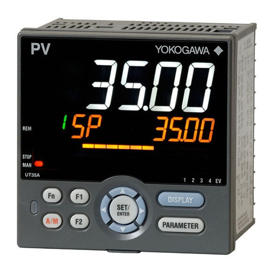
Chapter 3 Part Names Names and Functions of Display Parts (1) PV display (3) Symbol display (2) Group display (4) Data display (5) EXCEED indicator (8) Key navigation indicator (6) OUT indicator (9) Parameter display level indicator (7) Event indicator (10) Security indicator (2) + (3) + (4) : Setpoint display No. in figure Name Description... -
Page 27: Names And Functions Of Keys
Names and Functions of Keys (1) DISPLAY key (4) Light-loader interface (5) RST key (2) PARAMETER key (6) User function keys (3) SET/ENTER key Up/Down/Left/Right arrow keys No. in figure Name Description Used to switch the Operation Displays. Press the key in the Operation Display to switch the DISPLAY key provided Operation Displays. - Page 28 3.2 Names and Functions of Keys Maintenance Port (Power supply is not required for the UT35A-L). The maintenance port is used to connect with the dedicated cable when using LL50A Parameter Setting Software (sold separately). The parameters can be set without supplying power to the UT35A-L. Maintenance port Upper surface UT35A-L CAUTION When using the maintenance port, do not supply power to the controller. Otherwise, the controller does not work normally.
-
Page 29: List Of Display Symbols
List of Display Symbols The following shows the parameter symbols, menu symbols, alphanumeric of guide, and symbols which are displayed on the UT35A-L. Figure (common to all display area) PV display (14 segments): Alphabet Symbol display and Data display (11 segments): Alphabet (lower-case) IM 05P04D41-01EN... - Page 30 3.3 List of Display Symbols Group display (7 segments): Alphabet None PV display (14 segments): Symbol Space ‘ IM 05P04D41-01EN...
-
Page 31: Brief Description Of Setting Details (Parameters)
Brief Description of Setting Details (Parameters) This manual describes the Setting Details as follows in addition to the functional Description. Setting Details (Display Example) Parameter Display Name Setting range Menu symbol symbol level Set a display value of setpoint of PV alarm, SP alarm, deviation alarm, or velocity alarm. Alarm-1 to -3 A1 to A3 EASY -19999 to 30000 (Set a value... -
Page 32: Chapter 4 Basic Operation
Chapter 4 Basic Operation Overview of Display Switch and Operation Keys The following shows the transition of Operation Display, Operation Parameter Setting Display, and Setup Parameter Setting Display. The “Operation Parameter Setting Display” has the parameters for setting the functions necessary for the operation. The “Setup Parameter Setting Display” has the parameters for setting the basic functions of the controller. - Page 33 4.1 Overview of Display Switch and Operation Keys The display pattern of the UT35A-L is as follows; the Menu Display and Parameter Setting Display. For the Operation Display, see Chapter 6, “Monitoring and Control of Regular Operations.” Display Description The Menu Display is segmented by the function and optional terminal position.
- Page 34 4.1 Overview of Display Switch and Operation Keys Display Shown at the End (the Lowest Level) of the Parameter Setting Display As shown in the figure below, the END Display is shown to indicate the end of the Menu Display and Parameter Setting Display. There are no setting items. The scrolling guide of END is displayed. END is displayed. Basic Key Operation Sequence ● To move to the Setup Parameter Setting Display Hold down the PARAMETER (or PARA) key and the Left arrow key simultaneously for 3...
-
Page 35: How To Set Parameters
How to Set Parameters The following operating procedure describes an example of setting alarm setpoint (A1). Operation Hold down the PARAMETER key for 3 seconds in the Operation Display to call up the [SP] Menu Display. Press the SET/ENTER key to display the [SP] Parameter Setting Display. Press the Down arrow key to display the [A1] Parameter Setting Display. - Page 36 4.2 How to Set Parameters Press the Up or Down arrow key to change the setpoint. (Change the setpoint using the Up/Down arrow keys to increase and decrease the value and the Left/Right arrow keys to move between digits.) Press the SET/ENTER key to register the setpoint (the setpoint stops blinking). Press the PARAMETER key once to return to the Menu Display.
- Page 37 4.2 How to Set Parameters How to Set Parameter Setpoint Numeric Value Setting Display the Parameter Setting Display. Press the SET/ENTER key to move to the setting mode (the setpoint blinks). Press the Left arrow key to move one digit to the left. (Press the Right arrow key to move one digit to the right.) Press the Up or Down arrow key to change the setpoint.
- Page 38 4.2 How to Set Parameters Time (minute.second) Setting Example of 17 minutes 59 seconds Display the Parameter Setting Display. Press the SET/ENTER key to move to the setting mode (the setpoint blinks). Press the Left arrow key to move one digit to the left. (press the Right arrow key to move one digit to the right.) Press the Up or Down arrow key to change the setpoint.
- Page 39 Blank Page...
-
Page 40: Chapter 5 Quick Setting Function
Chapter 5 Quick Setting Function Setting Using Quick Setting Function Description The Quick setting function is a function to easily set the basic function of the controller. The Quick setting function starts when the power is turned on after wiring. The following lists the items to set using the Quick setting function. (1) Limit control type (High or low) (2) Input function (PV input, range, scale (at voltage/current input), etc.) IM 05P04D41-01EN... - Page 41 5.1 Setting Using Quick Setting Function Flowchart of Quick Setting Function Power ON Decide whether or not to use the Quick setting function. Press the UP arrow key to select YES. Press the SET/ENTER key to start the Quick setting function. Press the Down arrow key to select NO. Press the SET/ENTER key not to start the Quick setting function.
- Page 42 5.1 Setting Using Quick Setting Function Setting Example Set the following parameters to set to high limit control and thermocouple Type K (range: 0.0 to 500.0ºF). No need to change the parameters other than the following parameters. Set QSM = YES to enter the quick setting mode. (1) Set HI.LO = HIGH.
- Page 43 5.1 Setting Using Quick Setting Function Input Function Parameter Display Name Setting range Menu symbol symbol level OFF: Disable K1: -270.0 to 1370.0 ºC / -450.0 to 2500.0 ºF K2: -270.0 to 1000.0 ºC / -450.0 to 2300.0 ºF K3: -200.0 to 500.0 ºC / -200.0 to 1000.0 ºF J: -200.0 to 1200.0 ºC / -300.0 to 2300.0 ºF T1: -270.0 to 400.0 ºC / -450.0 to 750.0 ºF T2: 0.0 to 400.0 ºC / -200.0 to 750.0 ºF...
- Page 44 5.1 Setting Using Quick Setting Function Input Function (Continued) Parameter Display Name Setting range Menu symbol symbol level 0: No decimal place PV input scale 1: One decimal place decimal point EASY 2: Two decimal places position 3: Three decimal places 4: Four decimal places Maximum value of EASY PV input scale -19999 to 30000, (SL<SH),...
-
Page 45: Restarting Quick Setting Function
Restarting Quick Setting Function Once functions have been built using the Quick setting function, the Quick setting function does not start even when the power is turned on. The following methods can be used to restart the Quick setting function. ● Set the parameter QSM (Quick setting mode) to ON and turn on the power again. ● Set the parameter IN (PV input type) to OFF and turn on the power again. CAUTION The parameters related to the range or scale are initialized if the PV input type is changed. -
Page 46: Chapter 6 Monitoring And Control Of Regular Operations
Chapter 6 Monitoring and Control of Regular Operations Monitoring and Control of Operation Displays 6.1.1 Operation Display Transitions. When setup parameter When setup parameter HOME is set to PV. HOME is set to SP. PV Display SP Display (SP can be changed.) (SP can be changed.) SP Display PV Display (SP can be changed.) (SP can be changed.) Duration Time Display Maximum Value... - Page 47 6.1 Monitoring and Control of Operation Displays Details of the Operation Display The following is the Operation Display types and each display and operation description. PV display Setpoint display Operation Display Display and operation description PV display: Displays measured input value (PV). Setpoint display: Displays and changes target setpoint (SP). Symbol Target setpoint [SP Change Operation] SP Display (1) Press the SET/ENTER key to move to the setting mode (the setpoint blinks).
- Page 48 6.1 Monitoring and Control of Operation Displays (Continued) Operation Display Display and operation description PV display: Displays measured input value (PV). Setpoint display: Displays maximum value or minimum value. Maximum Symbol value Maximum/ Minimum Value Minimum Symbol Display value The maximum value or minimum value of PV is stored in the memory and display in the “HIGH” or “LOW” display in the confirmation display. When the control type is specified as high limit control, the maximum value is displayed in the “HIGH” display, and control type is specified as low limit control, the minimum value is displayed in the “LOW” display. When the PV exceeds SP and then returns to the normal status, Maximum / Minimum Value is retained as it is , but when PV exceeds SP again, it is automatically reset and starts taking new value for its...
-
Page 49: Setting Target Setpoint
Setting Target Setpoint Operation in the Operation Display Operation Bring the SP Display into view. Press the SET/ENTER key to move to the setting mode (the setpoint blinks). Press the Left arrow key to move one digit to the left. (Press the Right arrow key to move one digit to the right.) Press the Up or Down arrow key to change a setpoint. -
Page 50: Setting Alarm Setpoint
Setting Alarm Setpoint Setting Display Operation Display > PARAMETER key for 3 seconds (to [SP] Parameter Setting Display Menu Display) > SET/ENTER key (The setting parameter is displayed.) > Down arrow key (The setting parameter is displayed.) In the setting Display for the alarm parameters, Displays can be arbitrarily switched using the Up, Down, Left or Right arrow key. -
Page 51: Releasing On-State (Latch) Of Alarm Output
Releasing On-State (Latch) of Alarm Output Description Alarm latch can be released by any of the following. (1) User function key (2) Communication (3) Contact input For the switching operation by using the above, the last switching operation is performed. Releasing the alarm latch function releases all of the latched alarm outputs. By factory default, the function is not assigned to the user function key and contact input. -
Page 52: Chapter 7 Input (Pv) Functions
Chapter 7 Input (PV) Functions Setting Functions of PV Input 7.1.1 Setting Input Type, Unit, Range, Scale, and Decimal Point Position Description The figure below describes the case of PV input. Example of Temperature Input The figure below is an example of setting Type K thermocouple and a measurement range of 0.0 to 800.0 ºC. -270.0°C 1370.0°C Input type Set a range to be PV input range controlled. - Page 53 7.1 Setting Functions of PV Input Setting Details Parameter Display Name Setting range Menu symbol symbol level OFF: Disable K1: -270.0 to 1370.0 ºC / -450.0 to 2500.0 ºF K2: -270.0 to 1000.0 ºC / -450.0 to 2300.0 ºF K3: -200.0 to 500.0 ºC / -200.0 to 1000.0 ºF J: -200.0 to 1200.0 ºC / -300.0 to 2300.0 ºF T1: -270.0 to 400.0 ºC / -450.0 to 750.0 ºF T2: 0.0 to 400.0 ºC / -200.0 to 750.0 ºF...
-
Page 54: Setting Burnout Detection For Input
7.1 Setting Functions of PV Input (Continued) Parameter Display Name Setting range Menu symbol symbol level 0: No decimal place 1: One decimal place PV input scale decimal EASY 2: Two decimal places (Scaling) point position 3: Three decimal places 4: Four decimal places Maximum value of PV -19999 to 30000, (SL<SH), EASY (Scaling) input scale... -
Page 55: Setting Reference Junction Compensation (Rjc) Or External Reference Junction Compensation (Erjc)
RJC function of the controller can be turned off. External Reference Junction Compensation (ERJC) For TC input, a temperature compensation value for external device can be set. The external RJC can be used only when RJC = OFF. UT35A-L Terminal block Compensating lead wire Furnace UT35A-L... -
Page 56: Correcting Input Value
7.1 Setting Functions of PV Input 7.1.4 Correcting Input Value Setting Bias and Filter Description PV Input Bias The PV input bias allows bias to be summed with input to develop a measured value for display and control use inside the controller. This function can also be used for fine adjustment to compensate for small inter- instrument differences in measurement reading that can occur even if all are within the specified instrument accuracies. PV input bias is used for normal operation. PV input value PV input bias PV value inside the controller Temperature sensed... - Page 57 7.1 Setting Functions of PV Input Setting Details Parameter Display Name Setting range Menu symbol symbol level -100.0 to 100.0% of PV PV input bias EASY input range span (EUS) PVS PV input filter EASY OFF, 1 to 120 s Parameter Display Name Setting range Menu symbol symbol level -100.0 to 100.0% of each A.BS PV analog input bias input range span (EUS) A.FL PV analog input filter OFF, 1 to 120 s...
-
Page 58: Chapter 8 Function Block Diagram
Chapter 8 Function Block Diagram Function Block Diagram Equipped as standard Equipped as standard. PV input Contact inputs RS-485, Ethernet Com. Input type Input unit UNIT Input range/scale RH, RL SH, SL DI2.S PV analog input bias A.BS PV analog input filter A.FL PV input bias Latch release, etc... - Page 59 Blank Page...
-
Page 60: Chapter 9 Auxiliary Control Functions
Chapter 9 Auxiliary Control Functions Setting SP Limiter Description The SP high and low limits can be set to restrict the SP to the range between those limits. They works to the SP of all SP groups. 100.0 High limit of SP Setting range of actual SP Low limit of SP Setting range 100.0(%) -
Page 61: Setting Controller Action At Power On (Restart Mode)
Setting Controller Action at Power ON (Restart Mode) Description The state of output relay at power-on can be set by a setup parameter restart mode R.MD. For details, see Chapter 15, “Power Failure Recovery Processing.” Setting Details Parameter Display Name Setting range Menu symbol symbol level 0: Limit output is ON at power on in any cases. -
Page 62: Chapter 10 Retransmission Output Functions
Chapter 10 Retransmission Output Functions 10.1 Setting Retransmission Output Terminal, Type, and Scales Description The retransmission output can be used when the control output is not assigned to the analog output terminal. Confirm the output type selection (OT) before setting the retransmission output. The range can be changed. ► Current output range: 10.2 Changing Current Output Range Minimum value of Maximum value of... -
Page 63: Changing Current Output Range
10.2 Changing Current Output Range Description The analog output type can be selected from among 4 to 20, 0 to 20, 20 to 4, or 20 to 0 Setting Details Parameter Display Name Setting range Menu symbol symbol level 4-20: 4 to 20 mA, RET current output 0-20: 0 to 20 mA, RET.A... -
Page 64: Chapter 11 Alarm Functions
Chapter 11 Alarm Functions 11.1 Setting Alarm Type Description The alarm-related parameters consist of the alarm type (type, stand-by action, energized/ de-energized, and latch function), PV velocity alarm time setpoint, alarm hysteresis, alarm (On-/Off-) delay timer, and alarm setpoint. Alarm-related parameter Number of settings Alarm type 3 (number of settings) PV velocity alarm time setpoint 3 (number of settings) Alarm hysteresis 3 (number of settings) Alarm (on-/off-) delay timer... - Page 65 11.1 Setting Alarm Type PV High Limit Alarm and PV Low Limit Alarm PV high limit alarm output PV high limit Alarm hysteresis alarm setpoint Alarm hysteresis PV low limit alarm setpoint PV low limit alarm output Time Contact type in the figure above: Energized when an event occurs (factory default). 11-2 IM 05P04D41-01EN...
- Page 66 11.1 Setting Alarm Type Deviation High Limit Alarm and Deviation Low Limit Alarm Deviation high limit alarm output Alarm hysteresis Deviation high limit alarm setpoint (positive setpoint) Target setpoint (SP) Deviation low limit alarm setpoint (negative setpoint) Alarm hysteresis Deviation low limit alarm output Time Contact type in the figure above: Energized when an event occurs (factory default). When a negative setpoint is set for the deviation high limit alarm setpoint, the deviation setpoint will be lower than the SP.
- Page 67 11.1 Setting Alarm Type PV Velocity Alarm PV velocity alarm output Exceeds the velocity Monitors the variation of the measured value for 2 points by the time interval set in VT. Time Velocity alarm Velocity alarm setpoint setpoint Velocity alarm Velocity alarm An alarm occurs if the velocity time setpoint time setpoint exceeds this inclination.
- Page 68 11.1 Setting Alarm Type Stand-by Action The stand-by action is a function for ignoring the alarm condition and keeps the alarm off until the alarm condition is removed. Once the alarm condition is removed, the stand-by action is cancelled. It is effective in the following cases where; •...
- Page 69 11.1 Setting Alarm Type Alarm Latch Function The alarm latch function is a function for keeping the alarm output (keeping the alarm output on) after entering the alarm condition (alarm output is turned on) until an order to release the alarm latch is received. The alarm latch function has the following four types of action.
- Page 70 11.1 Setting Alarm Type Release of Alarm Latch The alarm latch function can be cancelled by the user function key or by contact input. Cancelling the alarm latch function cancels all latched alarm outputs. ► Release by user function key: 13.2 Assigning Function to User Function Key ► Release by contact input: 12.1.1 Setting Contact Input Function ► Release via communication: UTAdvanced Series Communication Interface User’s Manual PV high limit alarm setpoint Alarm hysteresis Alarm hysteresis PV low limit alarm setpoint...
- Page 71 11.1 Setting Alarm Type Setting Details Parameter Display Name Setting range Menu symbol symbol level AL1 to AL3 Alarm-1 to -3 type EASY See the table below. ALRM PV velocity alarm time 00.01 to 99.59 VT1 to VT3 EASY setpoint 1 to 3 (minute.second) Note1: The initial values of the parmeters AL1 to AL3 and VT1 to VT3 are "3". The following shows the example of setting PV high limit (01), With stand-by action (1), De-energized (1), and Latch 1 action (1). Symbol Alarm type Stand-by action...
-
Page 72: Setting Hysteresis To Alarm Operation
11.2 Setting Hysteresis to Alarm Operation Description If the On/Off switch of the alarm output is too busy, you can alleviate the busyness by increasing the alarm hysteresis. Hysteresis for PV High Limit Alarm Point of ON/OFF action Output (alarm setpoint) Hysteresis When Setting Hysteresis of 5ºC and 15ºC for PV High Limit Alarm HYS: 5ºC (example) HYS: 15ºC (example) Closed (ON) Closed (ON) Open... -
Page 73: Delaying Alarm Output (Alarm Delay Timer)
11.3 Delaying Alarm Output (Alarm Delay Timer) Description The alarm on-delay timer is a function for turning on the alarm when the alarm condition occurs, and the timer starts and the set time elapses. The timer is reset if the alarm condition is removed while the timer is running. No alarm is generated. -
Page 74: Chapter 12 Contact Input Functions
Chapter 12 Contact Input Functions 12.1 Setting Contact Input Function 12.1.1 Setting Contact Input Function Description The contact input (DI2) function works by setting the DI2.S parameter to functions such as the operation mode. Latch Release (LAT) Latch can be released using contact input. (Switch by the rising edge) Contact status Operation Remark... - Page 75 12.1 Setting Contact Input Function PV Red/white Switch (PVRW) PV color can be switched using contact input. (Status switch) Contact status Operation Remark Red color – White color – Set "10" to the parameter PCMD. Contact Action Type Operation Description Receiving a contact input signal changes the status to the specified operation, and Status a release changes the status back to the original action.
-
Page 76: Chapter 13 Display, Key, And Security Functions
Chapter 13 Display, Key, and Security Functions 13.1 Setting Display Functions 13.1.1 Setting Active Color PV Display Function The active color PV display function changes the PV display color when an event occurs. Description Link to Alarm The PV display color changes by linking to the alarm 1 or alarm 2. The following is an example of operation linking to alarm 1. Set the alarm-1 type to “PV high limit alarm” and alarm-1 setpoint to “80°C.” When the active color PV display switch is set to”2,” PV display color changes from white to red if PV exceeds the alarm-1 setpoint. The red-to-white switching action can be set. °C Alarm-1 hysteresis Alarm-1 setpoint A1 = 80°C 75°C Time... - Page 77 13.1 Setting Display Functions Link to PV The PV display color changes by linking to PV. Set the PV color change high limit to “70°C” and the PV color change low limit to “20°C.” PV display color changes from white to red if PV is out of the range. The red-to-white switching action can be set. There is no hysteresis. °C Parameter “PCH” (PV color change high limit) = 70°C 70°C Parameter “PCL” (PV color change low limit) = 20°C 20°C Time PV color: red PV color: red PV color: white...
- Page 78 13.1 Setting Display Functions Setting Details Parameter Display Name Setting range Menu symbol symbol level 0: Fixed in white 1: Fixed in red 2: Link to alarm 1 (Alarm OFF: white, Alarm ON: red) 3: Link to alarm 1 (Alarm OFF: red, Alarm ON: white) 4: Link to alarm 1 or 2 (Alarm OFF: white, Alarm ON: red) 5: Link to alarm 1 or 2 (Alarm...
-
Page 79: Masking Least Significant Digit Of Pv Display
13.1 Setting Display Functions 13.1.2 Masking Least Significant Digit of PV Display Description With and without least significant digit of the PV in the Operation Display can be set. When without least significant digit is set, the value of the least significant digit is truncated and not displayed. The internal value is not changed depending on whether with or without least significant digit (the value is for display only). This parameter does not function for the PV without decimal point. Least significant digit Least significant digit is displayed. -
Page 80: Setting Economy Mode
13.1 Setting Display Functions 13.1.3 Setting Economy Mode Description The LCD backlight ON/OFF can be set in the following methods. Setting the LCD backlight to OFF saves energy. User Function Keys The LCD backlight ON/OFF switch can be assigned to the user function key. ► User function key: 13.2 Assigning Function to User Function Key Backlight OFF timer The backlight OFF timer sets the economy mode parameter to ON. -
Page 81: Setting Message Function
13.1 Setting Display Functions 13.1.5 Setting Message Function Description Using the message function and turning the contact input on/off, the message registered beforehand can be displayed on PV display by interrupt. The message is registered using LL50A Parameter Setting Software. The messages are limited to 20 alphanumeric characters. A maximum of four messages can be registered. -
Page 82: Changing Guide Scroll Speed
13.1 Setting Display Functions 13.1.6 Changing Guide Scroll Speed Description The scroll speed can be changed when the guide for the parameter or menu is displayed. Setting Details Parameter Display Name Setting range Menu symbol symbol level Scroll speed (Slow) 1 to 8 (Quick) DISP 13.1.7 Turning Guide Display ON/OFF Description The guide display that appears when the parameter or the menu is displayed can be switched. - Page 83 13.1 Setting Display Functions 13.1.9 Setting Brightness and Contrast Adjustment of LCD and Display Update Cycle Description The brightness and contrast can be adjusted. The LCD has a characteristic that the display action becomes late at the low temperature. This can be solved by adjusting the display update cycle (D.CYC). Setting Details Parameter Display Name Setting range Menu symbol symbol level Brightness EASY (Dark) 1 to 5 (Bright) White brightness Adjusts the white brightness B.PVW adjustment of PV...
-
Page 84: Assigning Function To User Function Key
13.2 Assigning Function to User Function Key Description The UT35A-L has three user function keys on the front panel. Various functions can be assigned to the user function key. Press the user function key to perform the assigned function. The User function key is available only on the Operation Display. The assigned function does not work on the Parameter Setting Display. However, the Fn key can be used to turn on/off the guide display. -
Page 85: Setting Security Functions
13.3 Setting Security Functions 13.3.1 Setting a Password Description The password function can prevent inadvertent changes to the parameter settings. If a password is set, the checking is required when moving to the Setup Parameter Setting Display. When the password is verified, can be changed to the Setup Parameter Setting Display. -
Page 86: Locking (Hiding) Parameter Menu Display
13.3 Setting Security Functions 13.3.3 Locking (Hiding) Parameter Menu Display Description The parameter menu display lock function hides the following Parameter Menu Displays. Setting Details Parameter Display Name Setting range Menu symbol symbol level [CTL] menu lock [PV] menu lock [MPV] menu lock [OUT] menu lock R485 [R485] menu lock ETHR [ETHR] menu lock [KEY] menu lock... -
Page 87: Key Lock
13.3 Setting Security Functions 13.3.4 Key Lock Description The key lock function locks the key on the front panel to prohibit key operation. It can prohibit the operation mode switch or parameter setting change. Setting Details Parameter Display Name Setting range Menu symbol symbol level Front panel parameter data OFF: Unlock DATA KLOCK... -
Page 88: Confirmation Of Key And I/O Condition And Version
13.4 Confirmation of Key and I/O Condition and Version 13.4.1 Confirmation of Key and I/O Condition Description Can be confirm the Key and I/O condition. Setting Details Parameter Display Name Setting range Menu symbol symbol level Key status X000 DI1-DI2 status (equipped as standard) Read only. Y000 AL1-AL3 status (equipped as standard) Key confirmation parameters are displayed in hexadecimal. When the error occurs, "1"... - Page 89 13.4 Confirmation of Key and I/O Condition and Version Parameter KEY Displayed digit Description PARAMETER (or PARA) key (0: OFF, 1: ON) DISPLAY (or DISP) key (0: OFF, 1: ON) 1st digit RIGHT arrow key (0: OFF, 1: ON) DOWN arrow key (0: OFF 1: ON) SET/ENTER key (0: OFF, 1: ON) UP arrow key (0: OFF, 1: ON) 2nd digit LEFT arrow key (0: OFF, 1: ON)
-
Page 90: Confirmation Of Version
13.4 Confirmation of Key and I/O Condition and Version 13.4.2 Confirmation of Version Description Can be confirm the version of the controller. Setting Details Parameter Display Name Setting range Menu symbol symbol level MCU version EASY DCU version EASY ECU3 ECU-3 version EASY PARA Parameter version EASY H.VER Product version EASY Read only. VER SER1 Serial number 1... - Page 91 Blank Page...
-
Page 92: Chapter 14 Parameter Initialization
Chapter 14 Parameter Initialization 14.1 Initializing Parameter Settings to Factory Default Values Description Parameter settings can be initialized to the factory default values. Use the key or LL50A Parameter Setting Software to execute it. Note The user setting values (defaults) are not initialized even if the parameter setting values are initialized to the factory default values. -
Page 93: Registering And Initializing User Default Values
14.2 Registering and Initializing User Default Values 14.2.1 Registering as User Setting (Default) Values Description The user default values can be registered as parameter default values. Use the LL50A Parameter Setting Software to register user setting (default) values. CAUTION Before registering the user default value, make sure that the user setting value is set to the parameter. -
Page 94: Chapter 15 Power Failure Recovery Processing / Power Frequency Setting / Other Settings
Chapter 15 Power Failure Recovery Processing / Power Frequency Setting / Other Settings 15.1 Remedies if Power Failure Occurs during Operations Description All functions of the controller cannot be operated for about 10 seconds after recovery. However, the case of instantaneous power failure is excepted. • 100–240 V AC: Instantaneous power failure of 20 ms or less • 24 V AC/DC: Instantaneous power failure of 1 ms A power failure is not detected. Normal operation continues. The following shows effects caused in “settings”... -
Page 95: Power Frequency Setting
15.2 Power Frequency Setting Description The power frequency can be set by automatic detection or manually. However, when the /DC option is specified, only manual setting is available. Set the range to the commercial frequency of the installation location. Setting Details Parameter Display Name Setting range Menu symbol... -
Page 96: Chapter 16 Troubleshooting, Maintenance, And Inspections
Chapter 16 Troubleshooting, Maintenance, and Inspections 16.1 Troubleshooting 16.1.1 Troubleshooting Flowchart If the Operation Display does not appear after turning on the controller’s power, follow the measures in the procedure below. If a problem appears complicated, contact our sales representative. Is the controller defective? Completely Display I/O signal Communication... -
Page 98: Errors During Operation
16.1.3 Errors during Operation The errors shown below may occur during operation. Setpoint PV display Status indicator display Parameter that (Operation (Operation Error description Cause and diagnosis Remedy (Operation displays error details Display) Display) Display) Normal Setup parameter Analog input terminal ADC error Faulty AD.ERR indication –... - Page 99 16.1 Troubleshooting Hexadecimal Display on Setpoint Display (Operation Display) Some error codes are displayed in hexadecimal. When the error occurs, "1" is set on the bit of corresponding error, and the bit data is displayed in hexadecimal. If the setup parameter error or the operation parameter errors occur, it is displayed as follows: Data display 1st digit (hexadecimal)
- Page 100 16.1 Troubleshooting Hexadecimal Display of the Parameter which Shows the Error Details Error confirmation parameters are displayed in hexadecimal. When the error occurs, "1" is set on the bit of corresponding error. Data display 1st digit (hexadecimal) Symbol display 2nd digit (hexadecimal) 3rd digit (hexadecimal) 4th digit (hexadecimal) Parameter PA.ER Displayed digit Description 1st digit...
- Page 101 16.1 Troubleshooting Parameter AD1.E Displayed digit Description 1st digit ADC error of PV input – – – 2nd digit – RJC error of PV input – – 3rd digit PV input burnout error – – – 4th digit – – – – Parameter PV1.E Displayed digit Description 1st digit PV input burnout error – – – 2nd digit PV input over-scale PV input under-scale...
-
Page 102: Maintenance
16.2 Maintenance 16.2.1 Cleaning The front panel and operation keys should be gently wiped with a cloth soaked with water and squeezed firmly. CAUTION In order to prevent LCD from static electricity damage, do not wipe with dry cloth. (When LCD is electrified, it returns to normal in several minutes.) Do not use alcohol, benzene, or any other solvents. -
Page 103: Periodic Maintenance
16.3 Periodic Maintenance Check the operating condition periodically to use this instrument with good condition. 16-8 IM 05P04D41-01EN... -
Page 104: Disposal
16.4 Disposal When disposing of this instrument, arrange for appropriate disposal as industrial waste according to the rules of a country, the area, or a local government. 16-9 IM 05P04D41-01EN... - Page 105 Blank Page...
-
Page 106: Chapter 17 Installation And Wiring
Chapter 17 Installation and Wiring 17.1 Installation Location The instrument should be installed in indoor locations meeting the following conditions: • Instrumented panel This instrument is designed to be mounted in an instrumented panel. Mount the instrument in a location where its terminals will not inadvertently be touched. •... - Page 107 17.1 Installation Location Do not mount the instrument in the following locations: • Outdoors • Locations subject to direct sunlight, ultrared rays, ultraviolet rays, or close to a heater Install the instrument in a location with stable temperatures that remain close to an average temperature of 23°C. Do not mount it in locations subject to direct sunlight or close to a heater. Doing so adversely affects the instrument and LCD. •...
-
Page 108: Mounting Method
17.2 Mounting Method WARNING Be sure to turn OFF the power supply to the controller before installing it on the panel to avoid an electric shock. Mounting the Instrument Main Unit Provide an instrumented panel steel sheet of 1 to 10 mm thickness. After opening the mounting hole on the panel, follow the procedures below to install the controller: Insert the controller into the opening from the front of the panel so that the terminal... -
Page 109: External Dimensions And Panel Cutout Dimensions
17.3 External Dimensions and Panel Cutout Dimensions Unit: mm UT35A-L (approx. inch) (0.43) 65 (2.56) 96 (3.78) Bracket Terminal cover 20 (0.79) Bracket 1 to 10 mm (0.04 to 0.39 inch) (panel thickness) General mounting Side-by-side close mounting +0.8 – × 117 (4.61) min. +0.03 ([(N-1) 3.78+3.62]... -
Page 110: Wiring
Use a tester or similar device to ensure that no power is being supplied to a cable to be connected. 2) Wiring work must be carried out by a person with basic electrical knowledge and practical experience. 3) For the wiring cable, the temperature rating is 75 °C or more. UT35A-L Terminal Block Diagram -112 -412 -212 Do not use. - Page 111 17.4 Wiring CAUTION Do not use an unassigned terminal as the relay terminal. Recommended Crimp-on Terminal Lugs (ød) Recommended tightening torque: 0.6 N·m Applicable wire size: Power supply wiring 1.25 mm or more Applicable terminal lug Applicable wire size mm (AWG#) (ød) 0.25 to 1.65 (22 to 16) 5.5 3.3 Cable Specifications Purpose...
-
Page 112: Pv Input Wiring
4) If there is a risk of external lightning surges, use a lightning arrester etc. UT35A-L TC Input RTD Input (3-wire system) Compensating lead wire Shield –... -
Page 113: Limit Control Output (Relay) Wiring
Functional Reinforced insulation insulation A hazardous A hazardous voltage circuit voltage circuit Reinforced insulation DC Relay Wiring UT35A-L External DC power supply Relay Diode (Mount it directly to the relay coil UT’s contact Relay terminal (socket).) (Use one with a relay coil rating less than the UT’s contact rating.) -
Page 114: Contact Input Wiring
ON and the leakage current must be 100 µA or less when it is OFF. 4) If there is a risk of external lightning surges, use a lightning arrester etc. UT35A-L Contact Input Equipped as Standard No-voltage contact Transistor contact... -
Page 115: Contact Output Wiring
A hazardous A hazardous voltage circuit voltage circuit Reinforced insulation ► When using auxiliary relay: 17.4.3 Limit Control Output (Relay) Wiring UT35A-L Contact Output Equipped as Standard Relay contact Contact rating: 240 V AC, 1 A 30 V DC, 1 A (resistance load) The following table shows the initial status. AL1 terminal... -
Page 116: Retransmission Output Wiring
17.4 Wiring 17.4.6 Retransmission Output Wiring The current output range can be changed. RET terminals Shield – Receiver (Recorder etc.) Receiving resistor: Class D grounding Ω or less (grounding resistance of 100 Ω or less) 17-11 IM 05P04D41-01EN... -
Page 117: Communication Interface Wiring
RDA (–) SDB (+) SDA (–) Note ML2-x indicates a converter of YOKOGAWA. Other than this, RS232C/RS485 converters can also be used. If another converter is to be used, check the electrical specifications of the converter before using it. 17-12... -
Page 118: Ethernet Communication Interface Wiring
17.4 Wiring 17.4.8 Ethernet Communication Interface Wiring *Devices that can be *Devices that can be connected via Ethernet connected via Ethernet Ethernet Straight cable Crossing cable UT35A-L UT35A-L UT35A-L Upper side LED (baud rate) Lower side LED (link activity) Color Amber Color Green 100M bps Linked Unlit 10M bps Blink Active... - Page 119 Class D grounding Class D grounding (grounding resistance (grounding resistance of 100 Ω or less) of 100 Ω or less) Slave terminals UT35A-L Terminal (For Standard model) Suffix code: Type symbol 3 = “1” above (For Detailed model) Optional suffix code: /CH3 RDB (+) RDA (–) SDB (+) SDA (–)
-
Page 120: Power Supply Wiring
17.4 Wiring 17.4.9 Power Supply Wiring WARNING 1) Wiring work must be carried out by a person with basic electrical knowledge and practical experience. 2) Be sure to turn OFF the power supply to the controller before wiring to avoid an electric shock. Use a tester or similar device to ensure that no power is being supplied to a cable to be connected. -
Page 121: Attaching And Detaching Terminal Cover
17.5 Attaching and Detaching Terminal Cover After completing the wiring, the terminal cover is recommended to use for the instrument. Attaching Method (1) Attach the terminal cover to the rear panel (2) The following figure is a mounting image. of the main unit horizontally. When Ethernet communication is specified, cut and use a terminal cover as follows. -
Page 122: Chapter 18 Parameters
Chapter 18 Parameters 18.1 Parameter Map Brief Description of Parameter Map Group Display "E3" appearing in the parameter map are displayed on Group display (7 segments, 2 digits) while the menu or parameter is displayed. E3: indicates the parameter in E3-terminal area Parameter Display Level The marks below appearing next to the menu symbol and parameter symbol in the parameter map indicate the display/non-display level. - Page 123 18.1 Parameter Map Function of Each Menu The parameters in the menu of the following table indicate the parameters to set the functions necessary for operation. Menu symbol Function SP and alarm setpoint SP-related function ALRM Alarm function PV-related function The parameters in the menu of the following table indicate the parameters to set the basic functions of the controller.
- Page 124 18.1 Parameter Map Operation Setting parameters for the functions necessary for operations. display Press the key for 3 seconds. ALRM DYN1 DYN2 DYN3 DYF1 DYF2 DYF3 18-3 IM 05P04D41-01EN...
- Page 125 18.1 Parameter Map Operation Setting parameters for the basic functions of the controller display + Press the keys for 3 seconds. PASS R485 ETHR Displayed when a password has been set. HI.LO P.UNI UNIT P.DP P.RH RET.A P.RL RP.T ERJC A.BS IPAR A.FL...
- Page 126 18.1 Parameter Map DISP KLOC MLOC DI.SL PCMD COM.W DI2.S R.MD DATA X000 C.GRN Y000 FREQ R485 (E3) GUID ETHR (E3) PASS HOME SMEC DISP KLOC B.PVW DI.SL B.PVR B.SP B.BAR INIT B.STS D.CYC OP.JP MLSD ALRM 18-5 IM 05P04D41-01EN...
-
Page 127: List Of Parameters
18.2 List of Parameters 18.2.1 Operation Parameters SP and Alarm Setpoint Setting Menu (Menu: SP) Parameter Display Name Setting range Initial value symbol level 0.0 to 100.0% of PV input range Target setpoint EASY (EU) (Setting range: SPL to SPH) Set a display value of setpoint of PV alarm, deviation alarm, or velocity alarm. Alarm-1 to -3 A1 to A3 EASY -19999 to 30000 (Set a value setpoint within the input range.) - Page 128 18.2 List of Parameters Alarm Function Setting Menu (Menu: ALRM) Parameter Display Name Setting range Initial value symbol level Set a 5-digit value in the following order. [Alarm type: 2 digits (see below)] + AL1, AL3: PV [Without (0) or With (1) Stand-by action] high limit (01) + [Energized (0) or De-energized (1)] + Without Stand- [Latch action (0/1/2/3/4)] by action (0)
-
Page 129: Setup Parameters
18.2 List of Parameters 18.2.2 Setup Parameters Control Function Setting Menu (Menu: CTL) Parameter Display Name Setting range Initial value symbol level LOW: Low limit control HI.LO Limit control type EASY HIGH HIGH: High limit control The way of KEY: By key operation confirming EASY DI: By DI operation 18-8 IM 05P04D41-01EN... - Page 130 18.2 List of Parameters PV Input Setting Menu (Menu: PV) Parameter Display Initial Name Setting range symbol level value OFF: Disable K1: -270.0 to 1370.0 (°C) / -450.0 to 2500.0 (°F) K2: -270.0 to 1000.0 (°C) / -450.0 to 2300.0 (°F) K3: -200.0 to 500.0 (°C) / -200.0 to 1000.0 (°F) J: -200.0 to 1200.0 (°C) / -300.0 to 2300.0 (°F) T1: -270.0 to 400.0 (°C) / -450.0 to 750.0 (°F) T2: 0.0 to 400.0 (°C) / -200.0 to 750.0 (°F)
- Page 131 18.2 List of Parameters PV Input Setting Menu (Menu: PV) (Continued from previous page) Parameter Display Name Setting range Initial value symbol level 0: No decimal place PV input scale 1: One decimal place Depends on decimal point EASY 2: Two decimal places the input type position 3: Three decimal places 4: Four decimal places Maximum Depends on value of PV...
- Page 132 18.2 List of Parameters Output Setting Menu (Menu: OUT) Parameter Display Name Setting range Initial value symbol level OFF: Disable Retransmission EASY PV1: PV output type of RET SP1: SP Maximum value When RTS = PV1, SP1 100 % of PV of retransmission RTL + 1 digit to 30000 input range output scale of RET -19999 to RTH - 1 digit Decimal point position: When RTS=PV1 or SP1 decimal Minimum value...
- Page 133 18.2 List of Parameters RS-485 Communication Setting Menu (Menu: R485) (E3 terminal area) Parameter Display Name Setting range Initial value symbol level PCL: PC link communication PCLSM: PC link communication (with checksum) Protocol selection EASY MBRTU LADR: Ladder communication MBASC: Modbus (ASCII) MBRTU: Modbus (RTU) 600: 600 bps 1200: 1200 bps 2400: 2400 bps Baud rate EASY 4800: 4800 bps...
- Page 134 18.2 List of Parameters Ethernet Communication Setting Menu (Menu: ETHR) (E3 terminal area) Parameter Display Name Setting range Initial value symbol level High-speed EASY OFF, 1 to 8 response mode 9600: 9600 bps Baud rate EASY 19200: 19.2k bps 38400 38400: 38.4k bps NONE: None Parity EASY EVEN: Even EVEN ODD: Odd 0 to 255 IP1 to IP4 IP address 1 to 4 EASY...
- Page 135 18.2 List of Parameters Key Action Setting Menu (Menu: KEY) Parameter Display Name Setting range Initial value symbol level User function key-1, OFF: Disable F1 to F2 EASY -2 action setting LTUP: LCD brightness UP LTDN: LCD brightness DOWN BRI: Adjust LCD brightness User function key-n LCD: LCD backlight ON/OFF EASY action setting switch LAT: Latch release Display Function Setting Menu (Menu: DISP)
- Page 136 18.2 List of Parameters Display Function Setting Menu (Menu: DISP) (Continued from previous page) Parameter Display Name Setting range Initial value symbol level Guide display OFF: Nondisplay GUID ON/OFF ON: Display Home Operation PV: PV Display HOME Display setting SP: SP Display OFF: Disable 1: Economy mode ON (All indications except PV display OFF) Economy mode 2: Economy mode ON (All indications OFF) 3: Brightness 10 % (All indications) Brightness...
- Page 137 18.2 List of Parameters Menu Lock Setting Menu (Menu: MLOC) Parameter Display Name Setting range Initial value symbol level [CTL] menu lock [PV] menu lock [MPV] menu lock [OUT] menu lock R485 [R485] menu lock ETHR [ETHR] menu lock [KEY] menu lock OFF: Display DISP [DISP] menu lock ON: Nondisplay KLOC [KLOC] menu lock DI.SL [DI.SL] menu lock [I/O] menu lock...
- Page 138 18.2 List of Parameters DI Function Registration Menu (Menu: DI.SL) Parameter Display Name Setting range Initial value symbol level OFF: No function LAT: Latch release LCD: LCD backlight ON/OFF switch PVRW: PV red/white switch (*) DI2 function DI2.S MG1: Message display interruption 1 selection MG2: Message display interruption 2 MG3: Message display interruption 3 MG4: Message display interruption 4 *: Set the parameter PCMD=10.
- Page 139 18.2 List of Parameters Initialization Menu (Menu: INIT) Parameter Display Name Setting range Initial value symbol level Initialization to user 12345: Initialization, automatically U.DEF default value returned to "0" after initialization. Initialization to -12345: Initialization, automatically F.DEF factory default value returned to "0" after initialization. Error and Version Confirmation Menu (Menu: VER) Parameter Display...
- Page 140 The UT35A-L is a Limit Control Type Digital Indicating Controller that can be configured either as a high limit or as a low limit controller by a user. The UT35A-L complies with FM approval. The UT35A-L features universal input, three alarm out-...
- Page 141 Communication method : Two-wire half-duplex or four-wire half-duplex, start-stop synchronization, and non-procedural Baud rate : 600,1200,2400,4800,9600,19200 or 38400 bps Maximum communication distance : 1200 m Terminating resistor : 220Ω (External) All Rights Reserved. Copyright © 2011, Yokogawa Electric Corporation GS 05P04D41-01EN Mar.14, 2016-00...
- Page 142 0.00 to 20.00 mA Step Response Time Specifications (Response time at 63% of transmission output when a change is made stepwise in the range between 10 and 90% of input span) All Rights Reserved. Copyright © 2011, Yokogawa Electric Corporation GS 05P04D41-01EN Mar.14, 2016-00...
- Page 143 • Power consumption: 18 VA (For the /DC option. or less DC: 9 VA, AC: 14 VA) For analog output: ±0.05% of F.S. or less • Storage: Nonvolatile memory (Each within rated voltage range) All Rights Reserved. Copyright © 2011, Yokogawa Electric Corporation GS 05P04D41-01EN Mar.14, 2016-00...
- Page 144 (Suffix code: Type 3=1) SDB(+) Allowable range: (24 V AC/DC power supply: Option code /DC) 100-240 V AC SDA(-) (+10%, -15%) (free voltage) 50/60 Hz shared RDB(+) RDA(-) All Rights Reserved. Copyright © 2011, Yokogawa Electric Corporation GS 05P04D41-01EN Mar.14, 2016-00...
- Page 145 Adobe Reader 7 or later by Adobe Systems. n Accessory URL: http://www.yokogawa.com/ns/ut/im/ Model Name Terminal cover UTAP001 UTAP003 User’s Manual (CD) All Rights Reserved. Copyright © 2011, Yokogawa Electric Corporation GS 05P04D41-01EN Mar.14, 2016-00 Subject to change without notice.
-
Page 146: Appendix Input And Output Table
Appendix Input and Output Table Appendix 1 Input and Output Table UT35A Model and Suffix Codes Optional INPUT Model Suffix code suffix code ● ● ● ● ● ● ● ● UT35A Type 1: Basic control Type 2: Functions Type 3: Open networks Display language/Case color Fixed code Optional suffix codes ●: Equipped Description of symbol PV: Measured input RET: Retransmission output DI1 to DI2: Contact input AL1 to AL3: Alarm output OUT: Limit control output... - Page 147 Blank Page...
-
Page 148: Revision Information
Revision Information Title : UT35A-L Digital Indicating Controller (Limit Control Type) User’s Manual Manual No. : IM 05P04D41-01EN July 2011/1st Edition Newly published Aug. 2015/2nd Edition Safety standard IEC/EN 61010-2-201 conformity, Safety and EMC standard (3rd edition) confomity and error correction. n Written by... - Page 149 Blank Page...
- Page 150 3F Tower D Cartelo Crocodile Building, No.568 West Tianshan Road, Shanghai 200335, CHINA Phone : 86-21-62396262 Fax : 86-21-62387866 YOKOGAWA ELECTRIC KOREA CO., LTD. (Yokogawa B/D, Yangpyeong-dong 4-Ga), 21, Seonyu-ro 45-gil, Yeongdeungpo-gu, Seoul, 150-866, KOREA Phone : 82-2-2628-6000 Fax : 82-2-2628-6400 YOKOGAWA ENGINEERING ASIA PTE. LTD.
Need help?
Do you have a question about the UT35A-L and is the answer not in the manual?
Questions and answers