3onedata IES615-2DI Series User Manual
Managed industrial ethernet switch
Hide thumbs
Also See for IES615-2DI Series:
- Quick installation manual (3 pages) ,
- User manual (64 pages)

Related Manuals for 3onedata IES615-2DI Series


Summary of Contents for 3onedata IES615-2DI Series
- Page 1 IES615-2DI series Managed Industrial Ethernet switch User manual Version 1.0.0, Aug. 2017 www.3onedata.com...
- Page 2 Trademarks Notice is registered trademarks of 3onedata Co., Ltd. All other trademarks or registered marks in this manual belong to their respective manufacturers. Agreement As the product version upgrades or other reasons, this document is subject to change without notice.
-
Page 3: Table Of Contents
User Manual Content CHAPTER 1 SUMMARIZE......................... 1 1.1 Introduction ............................1 1.2 Features ............................... 1 CHAPTER 2 HARDWARE DESCRIPTION ....................2 2.1 Panel design ............................2 2.2 Power supply input ..........................3 2.3 Relay connection ..........................3 2.4 DIP switch ............................. 3 2.5 Communication port .......................... - Page 4 User Manual 5.11 Remote monitoring ........................... 42 5.11.1 SNMP management ....................... 42 5.11.2 Relay Alarm ..........................44 5.12 Traffic Statistics ..........................45 5.12.1 RX frame statistics ........................ 45 5.12.2 TX frame statistics......................... 46 5.13 Diagnosis ............................46 5.13.1 Mirror ............................46 5.14 Basic settings ...........................
-
Page 5: Chapter 1 Summarize
User Manual CHAPTER 1 SUMMARIZE 1.1 Introduction The IES615-2DI (3IN1) series is a managed industrial Ethernet switch that provides 5 Fast Ethernet ports, 2 three-in-one RS-232/485/422 serial ports. The electrical port supports 10 / 100M adaptive, MDI / MDI-X adaptive. Power supply supports 12 ~ 48VDC input. The -40~75℃... -
Page 6: Chapter 2 Hardware Description
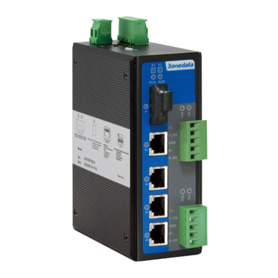
User Manual CHAPTER 2 HARDWARE DESCRIPTION 2.1 Panel design Vertical view and Bottom view Rear view Front view IES615-2DI (3IN1) IES615-1F-2DI (3IN1) IES615-2F-2D (3IN1) 1. Ground screw 2. 2-pin terminal block for relay output 3. Console port 4. 4-pin terminal block for power input 5. -
Page 7: Power Supply Input
User Manual 2.2 Power supply input The switch have redundant power input, provides one terminal block (4 bits) for PWR1 and PWR2 input. The redundant power can be used single and used two self-governed power to supply to the system, PWR1 and PWR2 input at the same time, when neither of these two power fails, the other power acts as a backup, and automatically supplies power needs, ensure running Ethernet reassuring. - Page 8 User Manual MDI-X — — 4, 5, 7, 8 Information necessary to explain: Note: ―TX±‖Transmitting data±, ―RX±‖receiving data±, ―—‖no use MDI(straight-through cable): MDI-X(Cross over cable): 100Base-FX fiber port 100Base-FX port works with full-duplex, SM or MM SC/ST/FC optional. The fiber port must be used in pair, TX (transmitting) port connects remote switch‘s RX (receive) port;...
-
Page 9: Serial Port Connection
User Manual 2.6 Serial port connection Serial port: The RS-232/485/422 serial port uses 5-pin terminal block as shown below. 1 2 3 4 5 PIN RS-232 RS-485 RS-422... -
Page 10: Led Indicator
User Manual 2.7 LED Indicator System Indication LED State Description PWR1 is connected and operates properly. PWR1 is not connected or operates abnormally. PWR2 is connected and operates properly. PWR2 is not connected or operates abnormally. ON/OFF The system is running abnormally. The system is running properly. - Page 11 User Manual Wiring Requirements Cable laying need to meet the following requirements, 1. It is needed to check whether the type, quantity and specification of cable match the requirement before cable laying; 2. It is needed to check the cable is damaged or not, factory records and quality assurance booklet before cable laying;...
-
Page 12: Chapter 3 Appearance And Dimension
User Manual Chapter 3 Appearance and Dimension 3.1 Appearance IES615-2DI(3IN1) IES615-1F-2DI(3IN1) IES615-2F-2DI(3IN1) 3.2 Dimension The series of products are the same size, but their types of interfaces are different. Unit (mm) -
Page 13: Chapter 4 Packling List
User Manual Chapter 4 Packing List Please check the packaging and accessories by your first using. Please inform us or our distributor if your equipments have been damaged or lost any accessories, we will try our best to satisfy you. Quantity Description Industrial Ethernet switch... -
Page 14: Chapter 5 Network Configuration
User Manual Chapter 5 Network Configuration 5.1 Modify IP address The switch default address is: 192.168.1.254, subnet mask is: 255.255.255.0. When entering into the switch Web interface through internet explorer, the IP address of the switch and PC must be in the same Local Area Network. -
Page 15: Login Web Server
User Manual 1. The lowest requirement for user's computer is as below: Install operating system (Windows XP/2000/7/8,etc) Install Ethernet card Install Web explorer (IE6.0 or higher version) Install and start TCP/IP protocol 2. Establish the correct network configuration The default management IP address of the switch: 192.168.1.254, subnet mask as: 255.255.255.0. -
Page 16: Main Menu
User Manual (Figure 5.3.1) 5.3.1 Main menu Menu Introduction: Main Menu Function Display device information and port information such System Status System information as software version, IP address, etc. COM Settings Serial parameter and Working mode configuration Serial Server Display incorrect data statistics and connection COM Information information that send by serial port. -
Page 17: System Status
3onedata Technology Co., Ltd. the registered trademark, the upper right corner of display is the current time, as shown in figure 5.4 show: (Figure 5.4) -
Page 18: Port Information
User Manual (Figure 5.4.1) 5.4.2 Port information The switch a total of 5 ports, ports can confirm whether the port with the equipment complies with the information bar. Equipment at work, via the port status of the port information in the status view, for example in the figure below you can see port 3 is LINK and port connection status as FULL, speed is 100M and port type for the TX(RJ45). - Page 19 User Manual Stop bits (bits) 1,1.5,2 The last of the data package The length of frame from Max frame space(bytes) 1-1460 serial data to Ethernet data. The time space from serial Character delay(ms) 1-500 data to Ethernet data Enter into the switch WEB interface, knock [Serial Server/COM settings]; please choice necessary configuration in drop down list, the serial configuration interface is as follows: (Figure 5.5.1) Configuration option: [Baud rate], [Parity], [Data Bits], [Stop Bits], [Max Frame Space], [Character Delay]...
- Page 20 User Manual RS-232, RS-485, RS-422 serial port Optional.
-
Page 21: Configure Working Mode
User Manual 5.5.2 Configure working mode Working mode configuration menu (Figure 5.5.2.1) [Sessions] Each serial port of serial device servers can support 1-4 sessions. It means serial port of serial device server send the received data to Ethernet through socket. More than one of the sessions means serial port of serial device server sends the received data to Ethernet through more than one socket. - Page 22 User Manual it will connect immediately. Data trigger: Once the switch receive the data, it will connect immediately. [Keep-alive] Setting the vacancy time for connection cut off automatic; if there do not have data transfer, the connection will cut off. If set ―0‖, means do not care how much time vacancy, the switch do not cut off voluntary.
- Page 23 User Manual how to create the Virtual COM port, please the VSP Management Software user manual. 1. Address pool just support Type A and type B address 2. Start address and end address must in the network segment. 3. Start address value must less than or equal to end address. Advanced mode 1.
-
Page 24: Com Information
User Manual 5.5.3 COM Information It main function of serial port information: Display incorrect data statistics and connection information that send by serial port. Figure as 5.5.3 (Figure 5.5.3) 5.6 Port Configuration 5.6.1 Port Settings The port configuration interface mainly include port type (Electric port or optical port), setup speed mode and duplex mode, flow control. - Page 25 User Manual Configuration Description Items Port Port name, corresponding to mark in panel. Type Display port type (TX or FX). Speed Display configurable speed of port or auto-negotiation mode. Auto-negotiation (AUTO), full duplex (FULL), half duplex (HALF) optional, Duplex default mode is auto-negotiation mode. Configurable ports enable or disable.
-
Page 26: Bandwidth Management
User Manual Two types of flow control: 1. In the half duplex mode, flow control is through back pressure. It is to send a jamming signal to the transmission source to reduce transmission speed. 2. In the full duplex mode, flow control generally follow IEEE802.3x standard. Switch sends "pause" to information source to pause its sending information. -
Page 27: L2 Features
User Manual (Figure 5.6.2.2) 5.7 L2 Features 5.7.1 VLAN The product supports based on 802.1Q VLAN. It deals with messages based on Tag of recognized message(including 802.1p priority and VLAN ID, etc.) Frames with 802.1q add 4 byte Tag based on Ethernet frames, including 2 byte TPID, 3 byte Priority, 1 byte CFI and 12 byte VLAN ID. - Page 28 User Manual Put the VLAN tag point to Port Put the VLAN tag point to Port Access default VLAN ID for message default VLAN ID for message Put the VLAN tag point to Port Keep up VLAN ID, no need Trunk default VLAN ID for message replace...
- Page 29 User Manual (Figure 5.7.1.1) We can know as the figure, the type of port 2, 3 is Trunk, can allow the data of VLAN 1 and VLAN 2 pass. 5. Modify VLAN It can re-configure existing VLAN including modifying member‘s type and quantity of the port. Steps are as follows: 1.
- Page 30 User Manual (Figure 5.7.1.3) 7. VLAN Configuration of Single Ring 1. Need to set one port as managed port, managed port and CPU port must in a same VLAN, figure as 5.7.1.4, port 1 is managed port. 2. The port that already set in ring network port, the VLAN port type must Trunk and take Tag, figure as 5.7.1.4.
-
Page 31: Igmp Snooping
User Manual (Figure 5.7.1.5) VLAN maximum support 64 VLAN item, VID value range:1~4095 Manged port is the port that manage and configure switch, it must in a same VLAN as CPU port 5.7.2 IGMP snooping IP host applies to join (or leave) multicast group to the neighboring router through IGMP (Internet Group Management Protocol) protocol. -
Page 32: Qos
User Manual The device provides the function of static MAC address forwarding. The destination address includes the data packets with static MAC address which will be transferred to the appointed port. Embedded forwarding address list in the switch chip can learn and support 2,000 MAC addresses and 16 multicast forwarding ports list. -
Page 33: Cos
User Manual (Figure 5.8.1.1) Users can select the QOS priority queue mechanism, the queue mechanism in two ways: weighted Fair mode and strict mode. Weighted Fair priority Weighted Fair refers to this port sends message according to queue priority High, Medium, Normal and low in proportion of 8:4:2:1 when some ports traffic is heavy. -
Page 34: Tos (Dscp)
User Manual The QoS technique developed by the working group, also known as class of service (CoS), is a 3-bit field called the Priority Code Point (PCP) within an Ethernet frame header when using VLAN tagged frames as defined by IEEE 802.1Q. It specifies a priority value of between 0 and 7 inclusive that can be used by QoS disciplines to differentiate traffic. -
Page 35: Redundancy
User Manual (AF) defines four service levels, each service level has 3 down process, so spent 12 DSCP values ((10,12,14), (18,20,22), (26,28,30), (34,36,38)). The priority value of the device (1-16) is defined as the lowest priority, as the first queue. Priority value (17-32) is defined as the second queue, the priority value (33-48) is defined as the third queue, the priority value (49-64 is defined as the fastest queue, the highest priority. -
Page 36: Rapid Ring
User Manual In telecommunications, trunking is a method for a system to provide network access to many clients by sharing a set of lines or frequencies instead of providing them individually. This is analogous to the structure of a tree with one trunk and many branches. Trunking is set by the configuration software, the two or more physical ports get together into a logical path to increase the bandwidth between the switch and the network node. - Page 37 User Manual and can facilitate the quick recovery of any network section of automatic system disconnected from the network. The switch supports maximum 4 ring groups. Each group set up 2 ports as Ring Port and a port cannot belong to several rings. Hello_time setting is time interval of sending detecting packet to network at regular time.
-
Page 38: Ring V3 Single Ring Configuration
User Manual (Figure 5.9.2.3) 3. Enable Ring Group 1(or Group 2), and enter into Network ID(support 0-255 number only). Select Ring Port between Port 1 and Port 2. ―Chain‖ refers to strengthen user‘s capability of making any type of redundant topological structure with flexibility by taking an advanced software technology. -
Page 39: Ring V3 Dual Ring Configuration
User Manual (Figure 5.9.2.5) 5.9.2.2 Ring V3 dual ring configuration Figure as 5.9.2.6, we can send dual ring is 2 rings combining, the point is number 105 switch Operating method: 1. Use the configure method of singe ring to configure 101, 102, 103, 104, 105 switch‘s port 1 and port 2 as ring port and group is 1 2. -
Page 40: Ring V3 Chain Configuration
User Manual Operating method: 1. Enable Ring Group 1 and Ring Group 2; (Hello_time can be disable too, if it enable, time of sending Hello packet could not be very fast, or it will influence CPU dealing speed.); 2. Set up Port 1 and 2 of Device 105, 106 to be Ring Ports in Ring Group 1, Network ID is 1, Ring Type Single;... -
Page 41: Ring V3 Dual_Homing Configuration
User Manual Chain (Figure 5.9.2.10) Operating method: 1. Enable Ring Group 1: Hello time can be disable too, if it enable, time of sending Hello packet could not be very fast, or it will influence CPU dealing speed. 2. Set up Port 4 and 5 of Device 100, 101, 102 and 103 to be Ring Port in Ring Group 1, Network ID is1, Ring Type is Single. - Page 42 User Manual Operating method: 1. Enable Ring Group 1 and Ring Group 2; (Hello_time can be disable too, if it enable, time of sending Hello packet could not be very fast, or it will influence CPU dealing speed.); 2. Set up Port 1 and 2 of Device 101, 102, 103, 104,105 to be Ring Ports in Ring Group 1, Network ID is 1, Ring Type Single;...
-
Page 43: Rapid Spanning Tree Protocol (Rstp)
User Manual (Figure 5.9.2.15) 5. Use a wire to connect Port 1 and 2 of Device 101-105 in turn to make a Single Ring. Use a wire to connect Port 1 and 2 of Device 118-122 in turn to make a Single Ring. Use a wire to connect Port 4 and 5 of Device 106-118 in turn to make a dual_homing. - Page 44 User Manual (Figure 5.9.3.1) Rapid Spanning Tree of concepts: Switch priority:As the bridge priority,the bridge priority and bridge MAC address combine bridge ID,the smallest ID bridge will become the root bridge on the network. Polling interval:how often send BPDU packet at one time. Forwarding delay:the port state of switch remain a forward delay time over the listening and learning.
-
Page 45: Access Profile
User Manual The example of Configuration: The priority of network bridge is ―32768‖,If there did not have network ID less than itself, itself is root network bridge. There did not have same network ID in network. Every 2 seconds, the network bridge will transmit BPDU message to all appoint port. If did not receive BPDU message more than 20 seconds, it realized port invalid, will calculate the status of network bridge again. -
Page 46: Remote Monitoring
User Manual (Figure 5.10.1) 1. User must remember user name and password after modified. If forget it, please use DIP switch to make default factory. The default user name and password: admin. 2. Set same user mane, the front settings of user name/password will be available. Remote monitoring 5.11 5.11.1 SNMP management... - Page 47 User Manual relationship of SNMP NMS and SNMP Agent. User can choose the following one or more features related to community name. 1. Defines MIB view of community name. 2. Setup visit privilege of MIB objective is Write or Read. Community name with Read privilege can check the device information only.
-
Page 48: Relay Alarm
User Manual The device supports warm start of Trap. If existed IP address in Trap gateway, click "Apply", the Trap receiver can get the trap information. If the trap receiver cannot get trap information, please check network setting and connecting. Please pay attention to the privilege of Read and Write in SNMP Explorer. -
Page 49: Traffic Statistics
User Manual 5.12 Traffic Statistics The function of traffic Statistics is to calculate the data packets in a fixed time, included transmit and receive data packets. Operate method: Start to calculate after select clear (Figure 5.12.1) 5.12.1 RX frame statistics Frame Name Description InUnicasts... -
Page 50: Tx Frame Statistics
User Manual InFiltered Valid frames filtered (because of VLAN and so on) 5.12.2 TX frame statistics OutUnicasts unicast data frames output OutBroadcasts Broadcast data frames output OutPause Number of output flow control pause frames OutMulticasts Multicast data frames output OutFCSErr Invalid FCS frames output OutOctets Number of output bytes(including FCS) -
Page 51: Basic Settings
User Manual (Figure 5.13.1) Mirror Port It defines a group of ports which are needed to be monitored. The device collects data from these ports. Monitored Port It defines a group of ports which are used to monitor other ports. The device outputs the data through these ports. - Page 52 User Manual Default gateway in the host PC is generally called default route. Default route refer to a kind of router that destination address of IP data packet will choose when it don‘t find other existing route. All data packets of destination address which don‘t exist in the list of router will choose default route.
-
Page 53: System Identification
User Manual 5.14.2 System identification In System Identification interface we can see Model, Name, Description, Serial NO., and Contact Information. We can modify these above items by this function. It will take effect after system reboot. Figure 5.14.2 is initial device settings of the switch. (Figure 5.14.2) Name To give a name to each device, length is not more than 16 bytes. -
Page 54: System File Upgrade
User Manual 5.14.3 System File Upgrade The menu included 5 functions: Factory default, Download Configuration, up load configuration, upgrade firmware. (Figure 5.14.3) 1. Factory Default If you know the IP address of the device, user name and password: Use IE to login Web interface. Click "System Management"... -
Page 55: Logout
User Manual Click "System File Update" Choose "Upload Configuration" Click "Upload" 4. Upgrade Firmware If you know the IP address of the device, user name and password: Use IE to login Web interface. Click "System Management" Click "System File Update" Choose "Upgrade Firmware"... -
Page 56: Appendix 1 Glossary Table
User Manual Appendix 1 Glossary table Glossary Description ARP (Address An IP address to physical address protocol Resolution Protocol) Auto-Negotiation Switches at both ends of the device in accordance with the maximum performance to auto-negotiate the speed and duplex mode Broadcast Storm A port send excessive broadcast frame meantime on the network, accumulate the respond to send messages on the network ,... - Page 57 User Manual...
-
Page 58: Appendix 2 Default Factory
User Manual Appendix 2 Default factory Main Menu Function Main Menu Name IndustrialSwitch Module ManagedSwitch System System Desription 5PORT status information Serial No. Contact information Port enable Enable Port Speed mode Consult automatic Port configuration configuratio Flow control enable Egress No cofiguration Bandwidth management... -
Page 59: Appendix 3 Treatment Of Common Problem
User Manual Appendix 3 Treatment of common problem 1. Why the page is not normal when configured by a web browser? Before the access to WEB interface, please clear the IE cache and cookies. Otherwise, the WEB interface may be not normal. 2.
Need help?
Do you have a question about the IES615-2DI Series and is the answer not in the manual?
Questions and answers