3onedata IES6210 Series User Manual
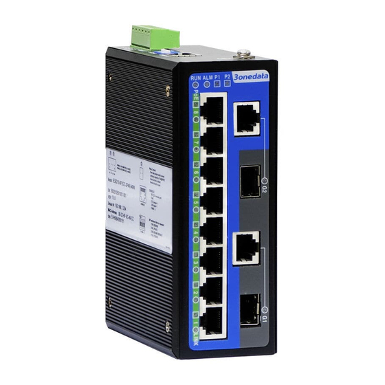
Managed industrial ethernet switch
Hide thumbs
Also See for IES6210 Series:
- Quick installation manual (4 pages) ,
- Quick installation manual (4 pages)

Subscribe to Our Youtube Channel
Related Manuals for 3onedata IES6210 Series


Summary of Contents for 3onedata IES6210 Series
- Page 1 IES6210 Series Managed Industrial Ethernet Switch (Optional POE) User Manual Version 01 Issue Date: 2019-01-22 Industrial Ethernet Communication Solutions Expert 3onedata Co., Ltd.
- Page 2 Purchased product, service or features should be constrained by 3ondedata commercial contracts and clauses. The whole or part product, service or features described in this document may beyond purchasing or using range. 3onedata won't make any statement or warranty for this document content unless any other appointment exists.
- Page 3 3onedata Co., Ltd. 3/B, Zone 1, Baiwangxin High Technology Industrial Park, Song Bai Road, Headquarter address: Nanshan District, Shenzhen, 518108, China Technology support: tech-support@3onedata.com Service hotline: +86-400-880-4496 E-mail: sales@3onedata.com Fax: +86-0755-26703485 Website: http://www.3onedata.com...
- Page 4 Managed Industrial Ethernet Switch User Manual Preface Managed Industrial Ethernet Switch User Manual has introduced this series of switches: Product feature Network management method Network management relative principle overview Readers This manual mainly suits for engineers as follows: Network administrator responsible for network configuration and maintenance ...
- Page 5 Managed Industrial Ethernet Switch User Manual Format Description operation may result in data loss or equipment damage. Pay attention to the notes on the mark, improper operation may cause personal injury. Make a necessary supplementary instruction for operation description. Configuration, operation, or tips for device usage. Pay attention to the operation or information to ensure success device configuration or normal working.
-
Page 6: Table Of Contents
LINK BACKUP ........................38 ......................38 APID 6.1.1 Instance: create single ring .................... 42 6.1.2 Instance: create coupling ring ..................44 6.1.3 Creating Spanning Tree ....................52 ......................56 RUNKING 6.2.1 Static Trunking ......................56 3onedata proprietary and confidential Copyright © 3onedata Co., Ltd. - Page 7 13.2 ..................84 ONFIGURATION ROBLEM 13.3 ....................85 LARM ROBLEM 13.4 ....................85 NDICATOR ROBLEM MAINTENANCE AND SERVICE ..................87 14.1 ....................87 NTERNET ERVICE 14.2 ....................87 ERVICE OTLINE 14.3 ................88 RODUCT EPAIR OR EPLACEMENT 3onedata proprietary and confidential Copyright © 3onedata Co., Ltd.
-
Page 8: Preface
Above 128MB Resolution Above 1024x768 Color Above 256 color Browser Above Internet Explorer 6.0 Operating System Windows XP Windows 7 1.2 Setting IP Address of PC The switch default management as follows: 3onedata proprietary and confidential Copyright © 3onedata Co., Ltd. - Page 9 Open "Control Panel > Network Connection> Local Area Connection> Properties> Internet Protocol Version 4 (TCP / IPv4)> Properties". Step 2 Change the selected "5" in red frame of the picture below to "1". 3onedata proprietary and confidential Copyright © 3onedata Co., Ltd.
-
Page 10: Log In The Web Configuration Interface
WebServer will provide 3 times opportunities to enter username and password. If enter the error information for 3 times, the browser will display a "Access denied" to reject access message. Refresh the page and try again. Step 5 Click "OK". 3onedata proprietary and confidential Copyright © 3onedata Co., Ltd. - Page 11 Step 6 End. After login in successfully, user can configure relative parameters and information according to demands. Notes: After login in the device, modify the switch IP address for usage convenience. 3onedata proprietary and confidential Copyright © 3onedata Co., Ltd.
-
Page 12: System Configuration
In "System Information" page, user can check "Device Information" and "Port Info". Operation Path Open in order: "Main Menu > System Config > System Information". Interface Description Device information interface as follows: 3onedata proprietary and confidential Copyright © 3onedata Co., Ltd. - Page 13 Display the contact information of the device maintenance personnel. Link status Port connection state, display state as follows: "LINK" represents connected port; "LOS" represents disconnected port. Port state Port work state, display state as follows: 3onedata proprietary and confidential Copyright © 3onedata Co., Ltd.
- Page 14 10.0.0.0/2. Gateway Fill in the gateway address information of device, e.g.: 10.0.0.1. Notes: Connect to the Internet to use NTP, please fill in the correct and available gateway and DNS address. 3onedata proprietary and confidential Copyright © 3onedata Co., Ltd.
-
Page 15: Port Configuration
After selecting automated negotiation, speed and duplex will be gained via automated negotiation. Operation Path Open in order: "Main Menu > Port Config > Port Setting". Interface Description Port setting interface as follows: 3onedata proprietary and confidential Copyright © 3onedata Co., Ltd. - Page 16 Click the drop-down list box of “Duplex” to select corresponding duplex mode of the port. Notes: When the speed mode is “AUTO”, the port will automatically match the opposite port mode, “Duplex” mode is disabled. 3onedata proprietary and confidential Copyright © 3onedata Co., Ltd.
-
Page 17: Sfp Ddm
This device’s SFP type Model Name Transmission wavelength of SFP module of the device port, Wavelength unit is: nm. The voltage that this device offers SFP. Its unit is V. Vcc(V) 3onedata proprietary and confidential Copyright © 3onedata Co., Ltd. -
Page 18: Poe Configuration
PD that connects to PSE is limited by the power of PoE power supply. Function Description The "PoE Config" page mainly includes: PoE total power settings; PoE port power settings; Priority settings; PoE port enablement. 3onedata proprietary and confidential Copyright © 3onedata Co., Ltd. - Page 19 Max power (W) Check the box to enable port PoE power function. Enabled Priority The priority configuration of PoE port power supply. Port power distribution priority with the constraint of gross power. 3onedata proprietary and confidential Copyright © 3onedata Co., Ltd.
-
Page 20: Bandwidth Management
Operation Path Open in order: “Main Menu > Port Configuration > Bandwidth Management”. Interface Description Interface printscreen of bandwidth management as follows: 3onedata proprietary and confidential Copyright © 3onedata Co., Ltd. - Page 21 Step 2 On the region of “Egress”, choose the egress bandwidth of port 1 as “4M”. Step 3 On the region of “Ingress”, conduct following operations on the row of port 1: Choose “Policy” as “Broadcast only”; 3onedata proprietary and confidential Copyright © 3onedata Co., Ltd.
- Page 22 Choose “Rate of Normal Priority Queue” as “2M”; Choose “Rate of Medium Priority Queue” as “4M”; Choose “Rate of High Priority Queue” as “8M”. Step 4 Click “Apply”. Step 5 End. 3onedata proprietary and confidential Copyright © 3onedata Co., Ltd.
-
Page 23: Layer 2 Features
Under the provisions of IEEE 802.1Q protocol, the device can add 4 bytes VLAN tag (Tag for short) between Source address and Length/Type fields of Ethernet data frame, identifying the VLAN information. As the picture below: 3onedata proprietary and confidential Copyright © 3onedata Co., Ltd. - Page 24 Operation Path Open in order: "Main Menu > L2 Feature > VLAN". Interface Description 1: Port-based VLAN Port-based VLAN interface as follows: The main elements configuration description of port-based VLAN interface: 3onedata proprietary and confidential Copyright © 3onedata Co., Ltd.
- Page 25 Click “Apply”, port 2 and port 3 are divided into VLAN3, port 2 and port 3 that belong to the same VLAN can transmit data to each other. Interface Description: VLAN based on 802.1Q Interface screenshot of VLAN based on 802.1Q as follows: 3onedata proprietary and confidential Copyright © 3onedata Co., Ltd.
- Page 26 PVID PVID (Port Default VLAN ID) port default VLAN ID, value range is 1-4094. Notes: If the port type is “access”, PVID will replace the 3onedata proprietary and confidential Copyright © 3onedata Co., Ltd.
- Page 27 VLAN configuration for all-purpose single ring Examples for typical VLAN configuration Example: Create IEEE 802.1Q VLAN Create a new IEEE 802.1Q VLAN. Operation steps Step 1 Open “Main Menu > L2 Feature > VLAN”. 3onedata proprietary and confidential Copyright © 3onedata Co., Ltd.
- Page 28 Step 8 Click “Apply”. Step 9 Open “Main Menu > Basic Settings > Network & Reboot”. Step 7 On the column of “Device Reboot”, click the button of “Reboot”. Step 10 END. 3onedata proprietary and confidential Copyright © 3onedata Co., Ltd.
- Page 29 Management port can manage and configure the switch; it must belong to the same VLAN to CPU port. Step 3 On the “Type” setting row of “VLAN Port Settings” column: Configure the “Type” of port 7 as “Trunk”. 3onedata proprietary and confidential Copyright © 3onedata Co., Ltd.
- Page 30 Step 8 Click “Apply”. Step 9 Open “Main Menu > Basic Settings > Network & Reboot”. Step 9 On the column of “Device Reboot”, click the button of “Reboot”. Step 10 END. 3onedata proprietary and confidential Copyright © 3onedata Co., Ltd.
- Page 31 Port 3, Port 4. Configure the "Type" of Port 3 and Port 4 to U. According to the forwarding entry analysis of Port 3, Port 4 and Port 5, forwarding entry design picture as follows: 3onedata proprietary and confidential Copyright © 3onedata Co., Ltd.
- Page 32 Step 10 On the column of “802.1Q VLAN Settings”, enter 4 in the “VID” text box of creating VLAN entry. Step 11 Conduct following operations on the drop-down list of “Type”: Select the “Type” of Port3 as Untagged. Select the “Type” of Port4 as Untagged. 3onedata proprietary and confidential Copyright © 3onedata Co., Ltd.
-
Page 33: Multicast Filtering
On the column of “Device Reboot”, click the button of “Reboot”. Step 13 End. 4.2 Multicast Filtering 4.2.1 IGMP Snooping Function Description On the “Dynamic multicast” page, user can: Enable/disable IGMP snooping Enable/disable IGMP query Routing mouth set 3onedata proprietary and confidential Copyright © 3onedata Co., Ltd. - Page 34 IGMP query interval, unit: second. Notes: The time range that can be entered is 60-1000s. Group survival The maximum time that multicast members in device can survive from existence to not receiving any response. Unit: 3onedata proprietary and confidential Copyright © 3onedata Co., Ltd.
-
Page 35: Static Filtering
On the page of “Static Multicast”, user can configure the forwarding port list of static multicast. Operation Path Open in order: “Main Menu > L2 Feature > Multicast Configuration”. Interface Description Static filtering interface as follows: 3onedata proprietary and confidential Copyright © 3onedata Co., Ltd. - Page 36 IGMP dynamic learning won’t update statically typed multicast address, static multicast forwarding table is more of a security mechanism. Example: Static Multicast Filtering Configuration For example: configure the filtering port of multicast address 01-00-00-00-00-01 as 01, 02 and 03. 3onedata proprietary and confidential Copyright © 3onedata Co., Ltd.
- Page 37 Tick the check box after “3-”. Step 4 Click “Add”. Step 5 Configured static filtering is displayed in the display frame on the bottom of the page, click “Apply”. Step 6 End. 3onedata proprietary and confidential Copyright © 3onedata Co., Ltd.
-
Page 38: Qos
Queuing mechanism Enable ToS Enable CoS Port priority Operation Path Open in order: “Main Menu > QoS > QoS Classification”. Interface Description Screenshot of QoS Classification interface: 3onedata proprietary and confidential Copyright © 3onedata Co., Ltd. - Page 39 Inspect CoS After checking the checkbox, the priority of CoS would be checked during queue scheduling. Default port priority To configurate default port priority for ports that haven’t 3onedata proprietary and confidential Copyright © 3onedata Co., Ltd.
-
Page 40: Cos Mapping
5.2 CoS Mapping Function Description On the page of “CoS Mapping”, user can configurate mapping between CoS value and priority queues. Operation Path Open in order: “Main Menu > QoS > QoS Mapping”. 3onedata proprietary and confidential Copyright © 3onedata Co., Ltd. - Page 41 1. When the CoS value is “0”,choose Low as the corresponding priority. 2. When the CoS value is “1”,choose Low as the corresponding priority. 3. When the CoS value is “2”,choose Normal as the corresponding priority. 3onedata proprietary and confidential Copyright © 3onedata Co., Ltd.
-
Page 42: Tos Mapping
On the page of “CoS Mapping”, user can configurate mapping between CoS value and priority queue. Operation Path Open in order: “Main Menu > QoS > ToS Mapping”. Interface Description Screenshot of ToS Mapping interface: 3onedata proprietary and confidential Copyright © 3onedata Co., Ltd. - Page 43 When the ToS value is set to 0x00~0x3C, the corresponding priority is Low. When the ToS value is set to 0x40~0x7C, the corresponding priority is Normal. When the ToS value is set to 0x80~0xBC, the corresponding priority is Medium. 3onedata proprietary and confidential Copyright © 3onedata Co., Ltd.
- Page 44 3. When the “ToS value” is “0x80”~“0xBC”, choose Medium as the corresponding priority. 4. When the “ToS value” is “0xC0”~“0xFC”, choose High as the corresponding priority. Step 3 Click “apply”. Step 4 Ends. 3onedata proprietary and confidential Copyright © 3onedata Co., Ltd.
-
Page 45: Link Backup
On the “Rapid ring” page, user can choose redundancy protocol and configure the ring network under this protocol quickly. Operation Path Open in order: “Main Menu > Redundancy > Rapid Ring”. Interface Description Initial rapid ring interface as follows: 3onedata proprietary and confidential Copyright © 3onedata Co., Ltd. - Page 46 Operation Path Open in order: “Main Menu > Redundancy > Rapid Ring”. Choose “Ring V3” in the drop-down list of “protocol of redundancy”. Interface Description Ring network interface as follows: 3onedata proprietary and confidential Copyright © 3onedata Co., Ltd.
- Page 47 Type According to the requirement in the scene, user can choose different ring network. Single: single ring, using a continuous ring to connect all 3onedata proprietary and confidential Copyright © 3onedata Co., Ltd.
- Page 48 Enable Enable or disable the corresponding ring group. Click “rapid ring state” to check the ring state of current ring network group configuration. Rapid ring state interface as follows: 3onedata proprietary and confidential Copyright © 3onedata Co., Ltd.
-
Page 49: Instance: Create Single Ring
6.1.1 Instance: create single ring Single ring could be created when the redundant protocol is “Ring V1”, “Ring V2” or “Ring V3”. Here we take creating single ring in Ring V3 for example. 3onedata proprietary and confidential Copyright © 3onedata Co., Ltd. - Page 50 In the setting area of the “Rapid Ring” page, choose “Ring V3” as the “protocol of redundancy”. Step 3 Check the box of “Enable” in “Group 1”. Step 4 Choose “Single” in the drop-down list of “Type” of “Group 1”. 3onedata proprietary and confidential Copyright © 3onedata Co., Ltd.
-
Page 51: Instance: Create Coupling Ring
When using Ring V2 to create coupling ring: “Port 1” represents “coupling port”, no control port. The creation process of coupling ring is same as that of Ring V3. 3onedata proprietary and confidential Copyright © 3onedata Co., Ltd. - Page 52 100, 101, 105 and 106 are in Ring 3. It is a coupling ring. Port 1 is coupling port. Port 2 is control port. Operation Step 1: configuring Ring 1 in WEB interface Configuring Device 105, 106, 107, 108 and 109 in the following steps respectively. 3onedata proprietary and confidential Copyright © 3onedata Co., Ltd.
- Page 53 Configuring Device 100, 101, 102, 103 and 104 in the following steps respectively. Step 1 Choose “Main Menu > Redundancy > Rapid Ring”. Step 2 In the “Settings” area of “Rapid Ring” page, choose “Ring V3” as “Protocol of Redundancy”. 3onedata proprietary and confidential Copyright © 3onedata Co., Ltd.
- Page 54 Check the “Enable” box in the “Group 2”. Step 4 Choose “Couple” in the drop-down list of “Type” of “Group 2”. Step 5 Enter “3” into the “ID” textbox of “Group 2”. 3onedata proprietary and confidential Copyright © 3onedata Co., Ltd.
- Page 55 The chain could be created when the “Protocol of Redundancy” is “Ring V3”. Instance For example: creating chain. Its basic architecture is shown as below: Instance analysis Basic framework, we can make the following analyses: 3onedata proprietary and confidential Copyright © 3onedata Co., Ltd.
- Page 56 Step 4 In the “settings” area of “Rapid Ring”: 1. Set “Type” to “Single”; 2. Set “ID” to “1”; 3. Set “Port 1” to “2”; 4. Set “Port 2” to “3”; 3onedata proprietary and confidential Copyright © 3onedata Co., Ltd.
- Page 57 In the “Settings” area of “Rapid Ring” page, set the “Type” to “Chain”. Step 5 In the “Settings” area of “Rapid Ring” page, set the “ID” to “2”. Step 6 Set “Port 1” to “02” and set “Port 2” to “03”. 3onedata proprietary and confidential Copyright © 3onedata Co., Ltd.
- Page 58 When forming complicated ring networks like tangent ring, please make sure the ID conforms to the unity of single ring network ID. Network ID of different single ring must be different. 3onedata proprietary and confidential Copyright © 3onedata Co., Ltd.
-
Page 59: Creating Spanning Tree
The main element configuration description of RSTP interface: Interface Element Description Protocol Choose the algorithm of redundancy protocol, options are: None: represents disabling ring network function; redundancy Ring V1: supports single ring; 3onedata proprietary and confidential Copyright © 3onedata Co., Ltd. - Page 60 Auto: adopt negotiation mechanism that could implement quick conversion of port states. Edge The switch that is on the edge of network and connects to the terminal devices. 3onedata proprietary and confidential Copyright © 3onedata Co., Ltd.
- Page 61 The path cost from this port to the root bridge is the lowest. When the path costs of multiple ports are the same, the one with the highest priority would be the root port. 3onedata proprietary and confidential Copyright © 3onedata Co., Ltd.
- Page 62 Blocking: port only receives and processes BPDU, doesn’t forward user flow; Disabled: blocked or physically disconnected. The settings of rapid spanning tree will take effect after rebooting the device. 3onedata proprietary and confidential Copyright © 3onedata Co., Ltd.
-
Page 63: Port Trunking
Enable or disable trunking configuration. Group Choose trunking group. Join port Check the box of ports that join the trunking group. Deal with Add, edit, delete or apply the configuration of port trunking group. 3onedata proprietary and confidential Copyright © 3onedata Co., Ltd. - Page 64 Setting one port as both ring network port and trunking port is not supported. Each trunking group should have 2 ports at least, up to 4. One port can only join a trunking group. 3onedata proprietary and confidential Copyright © 3onedata Co., Ltd.
-
Page 65: Lldp
Operation Path Open in order: “Main Menu > LLDP > Parameter Configuration”. Interface Description Parameter configuration interface as follows: Main elements configuration description of parameter configuration interface: Interface Elements Description 3onedata proprietary and confidential Copyright © 3onedata Co., Ltd. -
Page 66: Neighbor Information
Port description; System name; System function; Management address. Operation Path Open in order: “Main Menu > LLDP > Neighbor Information”. Interface Description Neighbor information interface as follows: 3onedata proprietary and confidential Copyright © 3onedata Co., Ltd. - Page 67 Management address is released to public after being packaged in Management Address TLV of LLDP message. 3onedata proprietary and confidential Copyright © 3onedata Co., Ltd.
-
Page 68: Access Control
On the “Login Settings” page, user can configure the login name and password of logging in to WEB configuration page and other parameter information. Operation Path Open in order: “Main Menu > Access control > Login settings”. Interface Description Login settings interface as follows: 3onedata proprietary and confidential Copyright © 3onedata Co., Ltd. - Page 69 1. Choose “1” as “Index” number 2. Choose “administrator” as “access level” 3. Enter “admin8” as “login name” 4. Enter “admin8” as “password” 5. Enter “admin8” as “confirm password”. Step 4 Click “apply”. Step 5 End. 3onedata proprietary and confidential Copyright © 3onedata Co., Ltd.
-
Page 70: Remote Monitoring
Configure SNMP V1/V2 read-only community name; Configure SNMP gateway. Operation Path Open in order: "Main Menu > Remote Monitoring > SNMP Configuration". Interface Description Interface screenshot of SNMP configuration as follows: 3onedata proprietary and confidential Copyright © 3onedata Co., Ltd. - Page 71 Notes: It will send out alarm during cold or warm start, port offline/online, power on/off. Please pay attention to the permission problem of read and write in the SNMP browser, 3onedata proprietary and confidential Copyright © 3onedata Co., Ltd.
-
Page 72: Relay Warning
Operation Path Open in order: "Main Menu > Remote Monitoring > Relay Warning". Interface Description Relay warning interface as follows: 3onedata proprietary and confidential Copyright © 3onedata Co., Ltd. - Page 73 Display the device power supply number. Alarm Setting Configure the power supply alarm function. Options as follows: Enable; Disable. Notes: DC provides 2 power supplies (AC without power supply 3onedata proprietary and confidential Copyright © 3onedata Co., Ltd.
- Page 74 On the region of "System Events", select "Enable" the "Alarm Setting" of power 1. Step 5 On the region of "Port Events", select "Enable" the "Alarm Setting" of power 1. Step 6 Click "Apply". Step 7 End. 3onedata proprietary and confidential Copyright © 3onedata Co., Ltd.
-
Page 75: Port Statistics
Operation Path Open in order: “Main Menu > Port Statistics > Frame Statistics”. Interface Description Frames statistics interface as follows: 3onedata proprietary and confidential Copyright © 3onedata Co., Ltd. - Page 76 FCS verification is invalid when the data frame length is less than 64 bytes. InOversize Received valid oversize data frames number. Notes: Oversize frames refer to those data frames whose length is more than 1518 or 1522 bytes. 3onedata proprietary and confidential Copyright © 3onedata Co., Ltd.
- Page 77 Multiple Successfully output data frames number after multiple times collision. OutFCSErr Output invalid FCS data frames number. Late Number of output frames with the occurrence of collisions after 64 bytes. 3onedata proprietary and confidential Copyright © 3onedata Co., Ltd.
-
Page 78: Network Diagnosis
Open in order: “Main Menu > Diagnosis > Mirror”. Interface Description Port mirror interface as follows: The main element configuration description of port mirror interface: Interface Element Description Mirror Setting port mirror function, options are: 3onedata proprietary and confidential Copyright © 3onedata Co., Ltd. - Page 79 In the option of “mirror port”, choose port “1”, “2” and “3”. Step 5 In the option of “collect port”, choose port “4”. Step 6 In the option of “watch direction”, choose “all”. Step 7 Click “apply”. Step 8 End. 3onedata proprietary and confidential Copyright © 3onedata Co., Ltd.
-
Page 80: System Management
Log information interface as follows: Main elements configuration description of log information interface: Interface Elements Description Log record Enable or disable log record. Display Type User can check the device booting, connection and 3onedata proprietary and confidential Copyright © 3onedata Co., Ltd. -
Page 81: Time Configuration
Selection of standard time zone for countries in the world. NTP Server Host name or IP address that provides NTP timing and time service for user. System Time Time of the device itself, after powering on, press 3onedata proprietary and confidential Copyright © 3onedata Co., Ltd. -
Page 82: Device Address
Configure gateway address; Configure DNS server; Reboot the device. Operation Path Open in order: “Main Menu > Basic Settings > Network & Reboot”. Interface Description Device address interface as follows: 3onedata proprietary and confidential Copyright © 3onedata Co., Ltd. - Page 83 Automatically obtain Configure the acquisition form of DNS server address as DNS server address automatic acquisition. Notes: When IP address is manual configuration, this option becomes gray and is not optional. 3onedata proprietary and confidential Copyright © 3onedata Co., Ltd.
-
Page 84: System Information
Step 4 Click “Apply”, system will automatically save the configuration. Step 5 End. 12.4 System Information Function Description On the page of “System Identification”, user can configure the following options: Device model; Device name; 3onedata proprietary and confidential Copyright © 3onedata Co., Ltd. - Page 85 The number length shouldn’t be more than 30 bytes. Contact Information Configure the contact Information of the device maintenance personnel. Notes: Support the entering of Chinese characters, English letters, 3onedata proprietary and confidential Copyright © 3onedata Co., Ltd.
-
Page 86: File Management
Restore factory defaults; Upload and download configuration files; System upgrading. Operation Path Open in order: "Main Menu > System Management > File Management". Interface Description File management interface as follows: 3onedata proprietary and confidential Copyright © 3onedata Co., Ltd. - Page 87 Upload Configuration Configure the switch via uploading configuration files information. Upgrade Firmware from Configuration column of system upgrade Local PC Upgrade Firmware Upgrade operating system of the switch. 3onedata proprietary and confidential Copyright © 3onedata Co., Ltd.
- Page 88 Alarm information is displayed in the pop-up dialog box of "messages from the webpage", click "OK". Step 8 The device is rebooted automatically and its configuration is updated. Step 9 End. 3onedata proprietary and confidential Copyright © 3onedata Co., Ltd.
-
Page 89: System Logout
Click “OK”. Step 6 Alarm information is displayed on the pop-up dialog box of “messages from the webpage”, click “OK”. Step 7 Login successfully to the WEB interface. Step 8 End. 3onedata proprietary and confidential Copyright © 3onedata Co., Ltd. -
Page 90: The Second Part: Frequently Asked Questions
Both of the initial user name and password are "admin". Is configuring via WEB browser same to configuring via BlueEyes_Ⅱ software? Both configurations are the same, without conflict. 3onedata proprietary and confidential Copyright © 3onedata Co., Ltd. -
Page 91: Configuration Problem
The port self-adaption state detection is conducted according to following order: 1000Mbps full duplex, 100Mbps full duplex, 100Mbps half-duplex, 10Mbps full duplex, 10Mbps half-duplex, detect in order from high to low, connect automatically in supported highest speed. 3onedata proprietary and confidential Copyright © 3onedata Co., Ltd. -
Page 92: Alarm Problem
Ethernet copper port and Combo port indicator are connected normally, but can't transmit data, what's the reason? When the system is power on or network configuration changes, the device and switch configuration in the network will need some time. Troubleshooting, after 3onedata proprietary and confidential Copyright © 3onedata Co., Ltd. - Page 93 Network cable is disturbed by static electricity or surge; Troubleshooting, change the shielded cable or install a lightning protector. High and low temperature influence; troubleshooting, check the device temperature usage range. 3onedata proprietary and confidential Copyright © 3onedata Co., Ltd.
-
Page 94: Maintenance And Service
Users using our company products can call technical support office. Our company has professional technical engineers to answer the questions and help solve the products or usage problems ASAP. Free service hotline: +86-400-880-4496 3onedata proprietary and confidential Copyright © 3onedata Co., Ltd. -
Page 95: Product Repair Or Replacement
According to the company's handling procedure, customers should negotiate with our company's technical staff and salesmen to complete the product maintenance, replacement or return. 3onedata proprietary and confidential Copyright © 3onedata Co., Ltd. - Page 96 Managed Industrial Ethernet Switch User Manual 3onedata Co., Ltd. Headquarter address: 3/B, Zone 1, Baiwangxin High Technology Industrial Park, Song Bai Road, Nanshan District, Shenzhen Technology support: tech-support@3onedata.com Service hotline: +86-400-880-4496 Official Website: http://www.3onedata.com 3onedata proprietary and confidential Copyright © 3onedata Co., Ltd.
Need help?
Do you have a question about the IES6210 Series and is the answer not in the manual?
Questions and answers