Table of Contents
Advertisement
Quick Links
One Technology Way • P.O. Box 9106 • Norwood, MA 02062-9106, U.S.A. • Tel: 781.329.4700 • Fax: 781.461.3113 •
Evaluating the ADXRS290 Dual-Axis Gyroscope
FEATURES
Flexible inertial sensor evaluation platform
Single main board operates with interchangeable
satellite boards
Separates DUT from controller for accurate
environmental testing
Continuous stream to file data recording
Standard USB cable for power and communications
PC-based graphical user interface (GUI)
Fast, easy installation
ONLINE RESOURCES
Evaluation Kit Contents
Mother board, satellite board
An USB A to Mini-B cable
An 18-inch, 20-pin ribbon cable
Documents Needed
ADXRS290
datasheet
Required Software
ISEB USB Driver
ISEB Run Time Engine
ADXRS290 Evaluation GUI Installer
Design and Integration Files
Schematics, layout files
EQUIPMENT NEEDED
PC running Windows
USB 2.0 port
PLEASE SEE THE LAST PAGE FOR AN IMPORTANT
WARNING AND LEGAL TERMS AND CONDITIONS.
Evaluation Board User Guide
www.analog.com
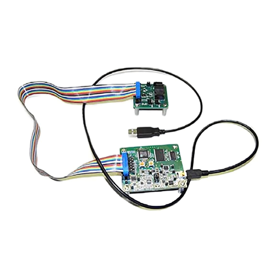
TYPICAL SETUP
Figure 1. EVAL-ADXRS290Z-M Evaluation System
Rev. 0 | Page 1 of 11
EVAL-ADXRS290Z-M
GENERAL DESCRIPTION
The iMEMS® ADXRS290 inertial sensor evaluation system
is an easy-to-use evaluation tool targeting bench or desktop
characterization of Analog Devices, Inc., inertial sensor products.
The system consists of the inertial sensor evaluation board (ISEB),
or main board, for any Analog Devices inertial sensor product.
The ISEB connects directly to a PC via an USB cable, with the
USB connection providing both communications and power to
the board. The ISEB is connected to the satellite board through
a ribbon cable. This cable allows the satellite to be easily
manipulated for testing or separately placed into an
environmental chamber for temperature or humidity testing.
Separating the boards mitigates corruption of data due to the
temperature and humidity effects of other components.
The ISEB is an universal main board and is intended to be used
with various satellites of Analog Devices inertial sensors, including
analog and digital accelerometers, as well as gyroscopes. The
different products are evaluated by means of separate GUIs that are
customized for performance and characterization measurements
relevant to the inertial sensor being evaluated. Since the power
consumption of gyro is relatively high compared with the
accelerometers, different shunt resistor have to be used to
detect its power consumption, the difference between
ADXRS290 –M with other –M is just the circuits for detecting
the power consumption of the gyroscope.
The EVAL-ADXRS290Z-M system contains the ISEB and the
EVAL-ADXRS290Z-S satellite board. Also included is an USB
A to Mini-B cable to connect the ISEB to a PC and an 18-inch,
20-pin ribbon cable to connect the ISEB to the satellite.
Advertisement
Table of Contents

Related Manuals for Analog Devices EVAL-ADXRS290Z-M


Summary of Contents for Analog Devices EVAL-ADXRS290Z-M
-
Page 1: Features
The system consists of the inertial sensor evaluation board (ISEB), Continuous stream to file data recording or main board, for any Analog Devices inertial sensor product. Standard USB cable for power and communications The ISEB connects directly to a PC via an USB cable, with the... -
Page 2: Table Of Contents
Evaluation Board User Guide EVAL-ADXRS290Z-M One Technology Way • P.O. Box 9106 • Norwood, MA 02062-9106, U.S.A. • Tel: 781.329.4700 • Fax: 781.461.3113 • www.analog.com Evaluating the ADXRS290 Dual-Axis Gyroscope TABLE OF CONTENTS Evaluation Board Circuitry ............7 Features ..................1 Gyroscope ................ -
Page 3: Getting Started
Evaluation Board User Guide EVAL-ADXRS290Z-M GETTING STARTED This section provides quick start procedures for using EVAL- ADXRS290Z-M board. Both the default and optional settings are described. The steps below should be followed to successfully set up and run the ADXRS290 evaluation system: Install the USB drivers for the inertial sensor evaluation system (ISEB). - Page 4 Figure 5. addition, as new firmware is made available, it can be downloaded Select Device Manager, expand the Ports (COM & LTP) from the Analog Devices FTP menu item as shown in Figure 6. ADI Inertial Sensor (ftp://ftp.analog.com/pub/iMEMS_Sensor_Eval/).
- Page 5 Evaluation Board User Guide EVAL-ADXRS290Z-M Click Browse… and select the ADI_ISEB_FW_XRS290.hex file. ADuC7026 Click Configure to display the box shown in Figure 8. The downloader file should be configured for the ADuC7026 microcontroller on the ISEB. This can be selected in the Parts tab.
-
Page 6: Evaluation Board Setup Procedures
Figure 1 shows typical bench characterization setup used to evaluate the EVAL- ADXRS290Z-M. Firstly, the EVAL-ADXRS290Z-M could be used to study and evaluate ADXRS290. User can view and save the real time output of ADXRS290 on PC for algorithm developing; check the noise performance of ADXRS290;... -
Page 7: Jumper Settings
Evaluation Board User Guide EVAL-ADXRS290Z-M JUMPER SETTINGS EVALUATION BOARD CIRCUITRY Set the jumper settings/link options on the evaluation board for This section describes the key parts on the development board. the required operating modes before powering on the board. GYROSCOPE The functions of the jumpers are described in Table 1. -
Page 8: How To Use The Software For Testing
Set Vs sets the supply voltage of the ADXRS290. The default shortcut to launch the executable is added to the Program Menu->Analog Devices – Inertial Sensor Eval. To launch the value is 3.3V. When the Set Vs knob is clicked, the ISEB applies the desired supply voltage, and then reads back the evaluation GUI, click ADXRS290 EVB GUI. -
Page 9: Real Time Data Tab
Evaluation Board User Guide EVAL-ADXRS290Z-M REAL TIME DATA TAB NOISE TAB Figure 16. Real Time Data Tab Figure 17. Noise Tab The Real Time Data tab configures the inertial sensor The Noise tab configures the ADXRS290 for real-time angular evaluation system and the ADXRS290 for real-time angular velocity monitoring and noise calculation. -
Page 10: Power Consumption Tab
UG-065 Evaluation Board User Guide POWER CONSUMPTION TAB TEMPERATURE TAB Figure 18. Power Consumption Tab Figure 19. Temperature Tab The Power Consumption tab contains two oscilloscope-like The Temperature tab as shown in Figure 19 is designed to interfaces that can be used to view the output of the 2-axes gyro facilitate temperature testing of the ADXRS290. - Page 11 By using the evaluation board discussed herein (together with any tools, components documentation or support materials, the “Evaluation Board”), you are agreeing to be bound by the terms and conditions set forth below (“Agreement”) unless you have purchased the Evaluation Board, in which case the Analog Devices Standard Terms and Conditions of Sale shall govern. Do not use the Evaluation Board until you have read and agreed to the Agreement.
Need help?
Do you have a question about the EVAL-ADXRS290Z-M and is the answer not in the manual?
Questions and answers