Table of Contents
Advertisement
Quick Links
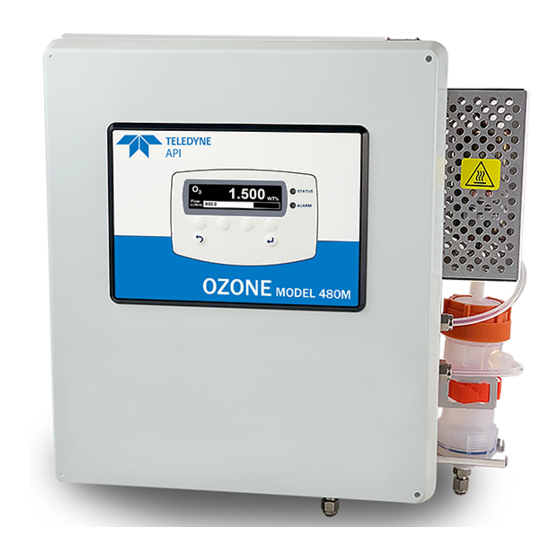
OZONE MONITOR
Toll-Free:
Phone:
Email:
Website:
Copyright 2021
Teledyne API
User Manual
Model 480M
Teledyne API (TAPI)
©
9970 Carroll Canyon Road
San Diego, CA 92131-1106
+1 800-324-5190
+1 858-657-9800
Fax
+1 858-657-9816
api-sales@teledyne.com
http://www.teledyne-api.com
09420A DCN8343
30 June 2021
Advertisement
Table of Contents

Subscribe to Our Youtube Channel
Related Manuals for TELEDYNE API 480M


Summary of Contents for TELEDYNE API 480M
- Page 1 User Manual Model 480M OZONE MONITOR Teledyne API (TAPI) © 9970 Carroll Canyon Road San Diego, CA 92131-1106 Toll-Free: +1 800-324-5190 Phone: +1 858-657-9800 +1 858-657-9816 Email: api-sales@teledyne.com Website: http://www.teledyne-api.com Copyright 2021 09420A DCN8343 Teledyne API 30 June 2021...
- Page 2 THIS PAGE IS INTENTIONALLY LEFT BLANK...
- Page 3 If you use this product in a manner other than that for which it was intended, unpredictable behavior could ensue with possible hazardous consequences. NEVER use any combustible/explosive gas with this product! 09420A DCN8343 Teledyne API Model 480M O Monitor User Manual...
- Page 4 été prévu, l’instrument pourrait se comporter de façon imprévisible et entraîner des conséquences dangereuses. NE JAMAIS utiliser de gaz explosive ou combustible avec cet produit! Teledyne API Model 480M O Monitor User Manual 09420A DCN8343...
- Page 5 Product Return All units or components returned to Teledyne API should be properly packed for handling and returned freight prepaid to the nearest designated Service Center. After the repair, the equipment will be returned, freight prepaid.
- Page 6 This page intentionally left blank Teledyne API Model 480M O Monitor User Manual 09420A DCN8343...
-
Page 7: Table Of Contents
6.3.1. MODBUS Commands Supported ....................40 6.3.2. Notes on MODBUS registers ...................... 40 6.3.3. Real-Time Concentration and Status Registers (Read Only) ............41 6.3.4. Instrument Setup and Configuration Registers (Read / Write)............ 41 09420A DCN8343 Teledyne API Model 480M O Monitor User Manual... - Page 8 TATUS UTPUTS 8.2.1. Sensor OK ........................... 55 8.2.2. Invalid Reading ........................... 55 8.2.3. Check Lamp..........................55 8.2.4. Pneumatic Error ......................... 55 8.2.5. Technical Assistance ........................56 9. PRINCIPLES OF OPERATION................57 Teledyne API Model 480M O Monitor User Manual 09420A DCN8343...
- Page 9 FIGURES Figure 3-1. Model 480M Display and Control Panel..................13 Figure 3-2: 480M Dimensions ........................16 Figure 3-3. AC Power Connection to Monitor ....................17 Figure 3-4. Interior Location of I/O Connectors .................... 19 Figure 3-5. Mainboard – Analog Output Configuration ................21 Figure 3-6.
- Page 10 Table 5-4. VARS List ............................ 34 Table 5-5. Alarm Configuration Settings ...................... 35 Table 6-1. RS-232/RS-485 Port Setup ......................38 Table 7-1. Maintenance Schedule ........................43 Table 8-1. Status LED/Output Definitions ....................54 viii Teledyne API Model 480M O Monitor User Manual 09420A DCN8343...
-
Page 11: Introduction
We at Teledyne API will be pleased to provide you with any support required so that you may utilize our equipment to the fullest extent. Our full time technical support department is always available to answer your questions. - Page 12 This page intentionally left blank Teledyne API Model 480M O Monitor User Manual 09420A DCN8343...
-
Page 13: Specifications And Agency Approvals
24 VDC, 30mA per output Max SPDT (Form C) Dry Contact, 250VAC, 5A High Current Relay Outputs (System OK, Global HI alarm, Global HI-HI alarm) Ethernet Communication Interface RS-232 / RS-485 09420A DCN8343 Teledyne API Model 480M O Monitor User Manual... -
Page 14: Approvals
2.2. APPROVALS This section presents Safety and Electromagnetic Compatibility (EMC) compliance approvals for the Model 480M monitor. 2.2.1. SAFETY IEC/EN 61010-1:2010 (3 Edition), Safety requirements for electrical equipment for measurement, control, and laboratory use. 2.2.2. EMC IEC/EN 61326-1:2010, Class A Emissions/Industrial Immunity FCC 47 CFR Part 15B, Class A Emissions 2.2.3. -
Page 15: Getting Started
Never allow organic contaminants, including but not limited to peroxides and chlorates, into monitor. Figure 3-1. Model 480M Display and Control Panel 09420A DCN8343 Teledyne API Model 480M O... -
Page 16: Unpacking
3.1. UNPACKING Upon receiving the 480M please verify that there is no apparent shipping damage. (If damage has occurred please advise shipper first, then Teledyne API). Check your packing slip for options that may be included, depending on your order, e.g., disposable sample inlet filters. - Page 17 09420A DCN8343 Teledyne API Model 480M O Monitor User Manual...
-
Page 18: Ac Power Connection
• quickly and easily accessible • clearly labeled as the disconnecting device for this instrument • Teledyne API Model 480M O Monitor User Manual 09420A DCN8343... -
Page 19: Wiring Instructions
• Neutral (White): Connect the Neutral wire to the terminal block directly across from the white wire that leads to the power supply. Figure 3-3. AC Power Connection to Monitor 09420A DCN8343 Teledyne API Model 480M O Monitor User Manual... -
Page 20: Electrical I/O Connections
There are two conduit penetrations on the enclosure, and an additional penetration can be added to one of the walls of the enclosure if needed. Teledyne API Model 480M O Monitor User Manual 09420A DCN8343... -
Page 21: Figure 3-4. Interior Location Of I/O Connectors
Figure 3-4. Interior Location of I/O Connectors 09420A DCN8343 Teledyne API Model 480M O Monitor User Manual... -
Page 22: Analog Output
• for Voltage output (0-5 VDC), jumper Pins 2-3 on both J15 and J17. 5. If applicable, reinstall/connect Relay Expansion board. 6. Re-secure the front panel (NEMA Configuration). 7. Reconnect power to the monitor. Teledyne API Model 480M O Monitor User Manual 09420A DCN8343... -
Page 23: Status Outputs
Electrically these outputs are optically isolated digital outputs that consist of open collector transistors with a common ground. They can be used to interface with devices that accept logic-level digital inputs, such as Programmable Logic Controllers (PLCs). 09420A DCN8343 Teledyne API Model 480M O Monitor User Manual... -
Page 24: High-Current Relay Outputs
Additionally, when the Failsafe is ON, the Alarm relays, HI Alarm and HI-HI Alarm behave the same as the System OK relay. In that the normal operating state, the relay coils are energized and the (NO) contact closes. Teledyne API Model 480M O Monitor User Manual 09420A DCN8343... -
Page 25: Digital Communication Interfaces
(see Figure 3-4) to a personal computer serial port. If communication cannot be established, it’s possible that the cable is pinned differently, and the signal pinout for the RS-232 connector can be swapped. See Section 6.2 for additional details. 09420A DCN8343 Teledyne API Model 480M O Monitor User Manual... -
Page 26: Pneumatic Connections
Provision must be made for keeping dust and other particulate matter out of the monitor and upstream sample delivery tubing. The monitor is equipped with an internal particulate filter at the inlet of the Sample line. Teledyne API Model 480M O Monitor User Manual 09420A DCN8343... -
Page 27: Exhaust Connection
Note that the monitor may be equipped with an internal ozone scrubber for removal of ozone from the exhaust stream. For safety reasons, the exhaust port must still be vented appropriately as described above. 09420A DCN8343 Teledyne API Model 480M O Monitor User Manual... -
Page 28: Pneumatic Flow Diagram
3.6. PNEUMATIC FLOW DIAGRAM Figure 3-7. Pneumatic Diagram Teledyne API Model 480M O Monitor User Manual 09420A DCN8343... -
Page 29: Calibration
Teledyne API if required. Teledyne API also recommends that the monitor be re-calibrated once a year. Teledyne API can provide NIST traceable calibration services at our factory or on-site. Please contact Technical Support for details on these services (see Section 8.2.4.2). - Page 30 This page intentionally left blank Teledyne API Model 480M O Monitor User Manual 09420A DCN8343...
-
Page 31: Operation
5.1. FRONT PANEL OVERVIEW The front panel provides a display screen, status LEDs and menu navigation and selection buttons. Figure 5-1. Front Panel Display and Controls 09420A DCN8343 Teledyne API Model 480M O Monitor User Manual... -
Page 32: Display
Alarm screen and a table which shows by a solid filled radio button whether there is a Hi Alarm or a Hi Hi Alarm. Teledyne API Model 480M O Monitor User Manual 09420A DCN8343... -
Page 33: Front Panel Menus
Enter button or exit without changing the setting by pressing the Back button. Note that limit checking is enforced while editing values and changes that would result in invalid values are ignored. 09420A DCN8343 Teledyne API Model 480M O Monitor User Manual... -
Page 34: Sensor Menu
4 mA 1.25 V 8 mA 2.50 V 12 mA 3.75 V 16 mA 100% 5.00 V 20 mA Press the Back button to exit from the Analog Step-Test function. Teledyne API Model 480M O Monitor User Manual 09420A DCN8343... - Page 35 If you are unsure regarding the suitability of a particular source of calibration gas, contact Technical Support at Teledyne API for assistance. In the Diag>Cal>Span Cal menu, use the buttons under the Up/Down arrow fields...
-
Page 36: Setup Menu
ETUP The VARS menu allows viewing and editing of various global setup variables that effect how the 480M operates. These variables are stored in the instrument’s non- volatile memory. Table 5-4 lists these variables and their function. Table 5-4. VARS List... -
Page 37: Table 5-5. Alarm Configuration Settings
Select Comm Addr to set the MODBUS address; the Register Maps are presented in Section 6.3. Select Ethernet to view Info or to set the IP Mode to Static or DHCP (Section 6.1). 09420A DCN8343 Teledyne API Model 480M O Monitor User Manual... -
Page 38: Status Screen
5.2.5. STATUS SCREEN Provides the status of Pneumatic, Sensor, Lamp, and Valid Reading functions, and becomes the default screen any time an Error occurs. See Section 8.2 for descriptions. Teledyne API Model 480M O Monitor User Manual 09420A DCN8343... -
Page 39: Digital Communications
6. DIGITAL COMMUNICATIONS The 480M comes equipped with digital communications capability that can be connected to a computer or digital data acquisition system (DAS). See Section 3.4.4 for configuration information. There is a serial communications connector that can be configured for RS-232 or RS485 and an Ethernet connector that uses Ethernet 10 Mbit standard. -
Page 40: Serial Configuration - Rs-232 And Rs-485
RS-232 connector, need to be changed to accommodate the serial cable pins. In that case, refer to Figure 6-1 to make the adjustments for 232 XSED OVER by setting the jumper pins 2-3 on both J20 and J23. Teledyne API Model 480M O Monitor User Manual 09420A DCN8343... -
Page 41: Figure 6-1. Rs-232/Rs-485 Signal Configurations
Figure 6-1. RS-232/RS-485 Signal Configurations 09420A DCN8343 Teledyne API Model 480M O Monitor User Manual... -
Page 42: Modbus Register Maps
6.3. MODBUS REGISTER MAPS 6.3.1. MODBUS COMMANDS SUPPORTED Table 6-2 lists the MODBUS commands that are supported by the 480M. Note that the “Write” commands will only work with registers that are configured as Read/Write, see Section 6.3.4. The “Read” commands can be used with any register. -
Page 43: Real-Time Concentration And Status Registers (Read Only)
Data Type # Bits Address Stream 1 HI Alarm STREAM_1_HI_ALARM_ENABLE Boolean Enable, 1=ON Stream 1 HI-HI Alarm Enable, STREAM_1_HI_HI_ALARM_ENABLE Boolean 1=ON Alarm Latch Mode, 1= Latching, 0= ALARM_MODE Boolean Non-Latching 09420A DCN8343 Teledyne API Model 480M O Monitor User Manual... - Page 44 Data Type Address Bits Inverse Stream 1 HI Alarm Limit (PPB) STREAM_1_HI_ALARM_SETPOINT Float(Double) Stream 1 HI-HI Alarm Limit Inverse STREAM_1_HI_HI_ALARM_SETPOINT (PPB) Float(Double) Inverse Stream 1 Analog Range (PPB) STREAM_1_RANG Float(Double) Teledyne API Model 480M O Monitor User Manual 09420A DCN8343...
-
Page 45: Maintenance
7.1. MAINTENANCE SCHEDULE Table 7-1 below outlines the suggested maintenance procedures and intervals for ensuring the 480M continues to operate accurately and reliably. These intervals are based on continuous (24 hours a day – 7 days a week) operation. These intervals may be lengthened for intermittent operation. -
Page 46: Instrument Layout
High voltage may be present when power is connected to the instrument. Figure 7-1 shows the internal layout of the 480M. These figures will be referenced in the procedures that follow. Note the caution areas, Power Supply and Electrical Terminal Block, where high voltage (line voltage) may be present when power is connected to the instrument. -
Page 47: Particulate Filter Replacement
8. Place the sample filter body on the sample body base and secure with the four screws and four washers. 9. Close the front panel. Figure 7-2. Particulate Filter (PN 02832) Replacement 09420A DCN8343 Teledyne API Model 480M O Monitor User Manual... -
Page 48: Sample Pump Replacement
9. Reconnect tubing; note that outlet fitting of pump should be connected to tubing routed to the ‘Exhaust’ fitting on rear panel. 10. Re-install new tubing clamps or cable-ties to secure tubing connections. Figure 7-3. J9 Pump Connector on Mainboard Teledyne API Model 480M O Monitor User Manual 09420A DCN8343... -
Page 49: Auto-Zero Valve Replacement
7.5. AUTO-ZERO VALVE REPLACEMENT 1. Disconnect power from the 480M. 2. Open front panel. 3. Locate the auto-zero valve (See Figure 7-1). 4. Unplug the two-pin valve connector from the mainboard PCA. 5. Remove the silver retainer clip from the top of the sensor valve. A pair of pliers may be used to slide off the retainer clip. -
Page 50: Uv Led Replacement
After installing and securing the replacement UV LED PCA assembly, it is recommended to perform a Zero Cal (see Section 5.2.3.2). Figure 7-4. O Sensor Module Board Figure 7-5. UV LED Access Teledyne API Model 480M O Monitor User Manual 09420A DCN8343... -
Page 51: Sensor Module Replacement
Then remove the four large socket head screws (Figure 7-6) that hold the mounting bracket in place. Do the reverse to install the replacement module. Figure 7-6. Sensor Module Removal 09420A DCN8343 Teledyne API Model 480M O Monitor User Manual... -
Page 52: Display Assembly Replacement
10. Route the display cable through the plastic retainers, locating the ferrite core in the center of the display. 11. Remove the tape backing from the ferrite core and press the ferrite core onto the door until well bonded. Teledyne API Model 480M O Monitor User Manual 09420A DCN8343... -
Page 53: Cleaning Exterior Surfaces
Figure 7-7. Display Assembly Removal 7.9. CLEANING EXTERIOR SURFACES If necessary, the front panel mask and keyboard of the 480M can be cleaned with a damp cloth. Do not attempt to clean any of the other surfaces of the instrument. Do not submerge any part of the instrument in water or cleaning solution. - Page 54 This page intentionally left blank Teledyne API Model 480M O Monitor User Manual 09420A DCN8343...
-
Page 55: Troubleshooting
Non-critical warnings are those that indicate some maintenance would be useful, but not immediately required. If the front panel LED indicates a status issue, details can be viewed in the STATUS 09420A DCN8343 Teledyne API Model 480M O Monitor User Manual... -
Page 56: Figure 8-2. Status Outputs
O3 Concentration > F.S. Range Check Lamp Reference < 250.0 mV OR Measure > 3120.0mV Pneumatic Pressure < 9.0 psia Error Pressure >18.0 .0 psia Flow < 500 cc/min Flow > 1100 cc/min Teledyne API Model 480M O Monitor User Manual 09420A DCN8343... -
Page 57: Sensor Ok
If the value then drops to within the acceptable range, then one of the sample lines is at elevated pressure. If the inlet is being pressurized, then the design of the sample system should be reviewed and corrected. 09420A DCN8343 Teledyne API Model 480M O Monitor User Manual... -
Page 58: Technical Assistance
If an issue persists, technical assistance may be obtained from: Teledyne API, Technical Support 9970 Carroll Canyon Road San Diego, California 92131-1106 USA Toll-free Phone: +1 800-324-5190 Phone: +1 858-657-9800 Fax: +1 858-657-9816 Email: api-techsupport@teledyne.com Website: http://www.Teledyne-API.com Teledyne API Model 480M O Monitor User Manual 09420A DCN8343... -
Page 59: Principles Of Operation
The detection of ozone molecules is based on absorption of 254 nm UV light due to an internal electronic resonance of the O 3 molecule. The 480M uses a UV LED constructed so that a large majority of the light emitted is at the 254nm wavelength. - Page 60 The voltage is converted into a number by a high resolution A/D (analog-to-digital) converter. The digitized signal, along with the other variables, is used by the CPU to compute the concentration using the above formula. Teledyne API Model 480M O Monitor User Manual 09420A DCN8343...
Need help?
Do you have a question about the 480M and is the answer not in the manual?
Questions and answers