Sign In
Upload
Manuals
Brands
TELEDYNE API Manuals
Measuring Instruments
480M
User Manuals: TELEDYNE API 480M Ozone Monitor
Manuals and User Guides for TELEDYNE API 480M Ozone Monitor. We have
1
TELEDYNE API 480M Ozone Monitor manual available for free PDF download: User Manual
TELEDYNE API 480M User Manual (72 pages)
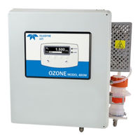
OZONE MONITOR
Brand:
TELEDYNE API
| Category:
Measuring Instruments
| Size: 10 MB
Table of Contents
Table of Contents
9
Introduction
13
Specifications and Agency Approvals
15
Model 480M Specifications
15
Compliance and Certifications
16
Getting Started
17
Figure 3-1. Model 480M Display and Control Panel
17
Unpacking
18
Mechanical Installation
18
Ac Power Connection
20
Wiring Requirements
20
Figure 3-2: 480M Mounting Hole Locations and Dimensions
20
Wiring Instructions
21
Figure 3-3. AC Power Connection to Monitor
21
Electrical I/O Connections
22
Figure 3-4. Interior Location of I/O Connectors
23
Analog Output
24
Status Outputs
25
Figure 3-5. Mainboard - Analog Output Configuration
25
High-Current Relay Outputs
26
Failsafe Operation Signal and Relay Outputs
26
Table 3-1. Status Output Definitions
26
Table 3-2. Relay Functions
26
Digital Communication Interfaces
27
Pneumatic Connections
28
Sample Inlet Connection
28
Figure 3-6. Pneumatic Connections
28
Exhaust Connection
29
Pneumatic Flow Diagram
30
Figure 3-7. Pneumatic Diagram
30
Calibration
31
Factory Calibration
31
Zero, Span, and Flow Calibrations
31
Operation
33
Front Panel Overview
33
Figure 5-1. Front Panel Display and Controls
33
Display
34
Control Keys
34
Indicator Leds
34
Figure 5-2. Front Panel Selection and Control Buttons
34
Front Panel Menus
35
Editing Settings
35
Table 5-1. Menu Structure
35
Sensor Menu
36
Diag Menu
36
Table 5-2. Sensor Menu Parameters
36
Table 5-3. Analog Step Test Values
36
Setup Menu
38
Table 5-4. VARS List
38
Table 5-5. Alarm Configuration Settings
39
Status Screen
40
Digital Communications
41
Ethernet Configuration
41
Serial Configuration - Rs-232 and Rs-485
42
Table 6-1. RS-232/RS-485 Port Setup
42
Figure 6-1. RS-232/RS-485 Signal Configurations
43
Modbus Register Maps
44
MODBUS Commands Supported
44
Notes on MODBUS Registers
44
Real-Time Concentration and Status Registers (Read Only)
45
Instrument Setup and Configuration Registers (Read / Write)
46
Maintenance
47
Maintenance Schedule
47
Table 7-1. Maintenance Schedule
47
Instrument Layout
48
Figure 7-1. Instrument Layout
48
Pneumatic Leak Check
49
Particulate Filter Replacement
49
Sample Pump Replacement
50
Figure 7-2. Particulate Filter (PN 02832) Replacement
50
Auto-Zero Valve Replacement
51
Figure 7-3. J9 Pump Connector on Mainboard
51
Uv Led Replacement
52
Figure 7-4. O Sensor Module Board
52
Sensor Module Replacement
53
Figure 7-5. UV LED Access
53
Figure 7-6. Sensor Module Removal
54
Display Assembly Replacement
55
Cleaning Exterior Surfaces
56
Removing/Installing Relay Expansion Board
56
Figure 7-7. Display Assembly Removal
56
Figure 7-8. Relay Board Removal
57
Boot Loader Operation
58
Boot Loader - Full Instrument Update
58
Figure 7-9. J7 Bootload Configuration
58
Boot Loader - Recovery Option
64
Troubleshooting
65
Reference Drawings
65
Troubleshooting Using Front Panel Status Led and Status Outputs
65
Figure 8-1. Display and Control Panel
65
Figure 8-2. Status Outputs
66
Table 8-1. Status Led/Output Definitions
66
Sensor OK
67
Invalid Reading
67
Check Lamp
67
Pneumatic Error
67
Technical Assistance
68
Principles of Operation
69
Advertisement
Advertisement
Related Products
TELEDYNE API 480L
TELEDYNE API 465M
TELEDYNE API 465H
TELEDYNE API 452
TELEDYNE API 470
TELEDYNE API Everywhereyoulook 480H
TELEDYNE API 465L
TELEDYNE API API-465H
TELEDYNE API API-465M
TELEDYNE API N100
TELEDYNE API Categories
Measuring Instruments
Accessories
Monitor
Recording Equipment
Portable Generator
More TELEDYNE API Manuals
Login
Sign In
OR
Sign in with Facebook
Sign in with Google
Upload manual
Upload from disk
Upload from URL