Table of Contents
Advertisement
Quick Links
Copyright 2019
Teledyne API
User Manual
Model T500U
CAPS NO
2
with NumaView™ software
© TELEDYNE API (TAPI)
9970 CARROLL CANYON ROAD
SAN DIEGO, CALIFORNIA 92131-1106
USA
Toll-free Phone:
Phone:
Fax:
Email:
Website:
Analyzer
+1 800-324-5190
+1 858-657-9800
+1 858-657-9816
api-sales@teledyne.com
http://www.teledyne-api.com/
083730510A DCN8172
05 September 2019
Advertisement
Table of Contents
Troubleshooting

Related Manuals for TELEDYNE API T500U


Summary of Contents for TELEDYNE API T500U
- Page 1 User Manual Model T500U CAPS NO Analyzer with NumaView™ software © TELEDYNE API (TAPI) 9970 CARROLL CANYON ROAD SAN DIEGO, CALIFORNIA 92131-1106 Toll-free Phone: +1 800-324-5190 Phone: +1 858-657-9800 Fax: +1 858-657-9816 Email: api-sales@teledyne.com Website: http://www.teledyne-api.com/ Copyright 2019 083730510A DCN8172...
- Page 3 NOTICE OF COPYRIGHT © 2019 Teledyne API (TAPI). All rights reserved. TRADEMARKS All trademarks, registered trademarks, brand names or product names appearing in this document are the property of their respective owners and are used herein for identification purposes only.
- Page 4 NEVER use any gas analyzer to sample combustible gas(es)! For Technical Assistance regarding the use and maintenance of this instrument or any other Teledyne API product, contact Teledyne API’s Technical Support Department: Telephone: +1 800-324-5190 Email: api-techsupport@teledyne.com...
- Page 5 été prévu, l’instrument pourrait se comporter de façon imprévisible et entraîner des conséquences dangereuses. NE JAMAIS utiliser un analyseur de gaz pour échantillonner des gaz combustibles! 083730510A DCN8172 Teledyne API T500U CAPS NO Analyzer with NumaView™ Software...
-
Page 6: Warranty
PRODUCT RETURN All units or components returned to Teledyne API should be properly packed for handling and returned freight prepaid to the nearest designated Service Center. After the repair, the equipment will be returned, freight prepaid. - Page 7 Provides information about that which could either affect accuracy of instrument readings or cause loss of data. Provides information pertinent to the proper care, Note operation or maintenance of the instrument or its parts. 083730510A DCN8172 Teledyne API T500U CAPS NO Analyzer with NumaView™ Software...
-
Page 8: Table Of Contents
Downloading DAS (Data Acquisition System) Data ..........49 Setup>Events ........................50 Editing or Deleting Events ..................52 Using Events as Triggers for Data Logging ............53 Setup>Dashboard ........................ 53 Teledyne API T500U CAPS NO Analyzer with NumaView™ Software 083730510A DCN8172... - Page 9 Software/Firmware Updates ......................86 Remote Updates ........................86 Manual Reload/Update Procedures ..................86 Time Zone Changes ........................88 Hardware Maintenance Procedures ....................89 Replacing the Sample Filter ....................89 083730510A DCN8172 Teledyne API T500U CAPS NO Analyzer with NumaView™ Software...
- Page 10 Removing / Replacing the Relay PCA from the Instrument ........ 110 Frequently Asked Questions ......................111 Technical Assistance ........................112 6. PRINCIPLES OF OPERATION ......................113 Glossary ............................... 115 viii Teledyne API T500U CAPS NO Analyzer with NumaView™ Software 083730510A DCN8172...
-
Page 11: List Of Figures
Figure 4-2. Zero and Span Calibration Screens ..................78 Figure 4-3. Auto Cal Page........................... 79 Figure 5-1: Report Generation Page ......................85 Figure 5-2. Remote Update Page ....................... 86 083730510A DCN8172 Teledyne API T500U CAPS NO Analyzer with NumaView™ Software... - Page 12 Table 2-14. LAN/Ethernet Configuration Properties ................... 64 Table 3-1. Ethernet Status Indicators ......................67 Table 3-2. Teledyne API's Hessen Protocol Response Modes ..............71 Table 3-3. Hessen Status Flags and Default Bit Assignments ..............72 Table 4-1. AUTO CAL States ........................80 Table 4-2.
-
Page 13: Introduction, Specifications, Approvals, & Compliance
(lost light) is directly proportional to the path-length and the concentration of the absorbing gas (Beer-Lambert law), providing direct measurement of NO The T500U uses few components: an optical cell, a pair of highly reflective spherical mirrors centered at 450nm (strong NO absorbance band), a light emitting diode (LED), and a vacuum photodiode detector. -
Page 14: Epa Designation
• Intended for Indoor Use Only at Altitudes ≤ 2000m Note: All specifications are based on constant conditions EPA DESIGNATION Teledyne API’s Model T500U cavity attenuated phase shift spectroscopy nitrogen dioxide analyzer is officially designated as a US EPA Federal Equivalent Method (FEM), Designation number EQNA-0514-212 for NO measurement as defined in 40 CFR Part 53. -
Page 15: Emc
IEC/EN 61326-1, Class A Emissions/Industrial Immunity FCC 47 CFR Part 15B, Class A Emissions CE: 2004/108/EC, Electromagnetic Compatibility Directive OTHER CERTIFICATIONS EU: EN14211 TÜV Rheinland QAL1 Certified: EN15267 MCerts: Sira MC160304/00 083730510A DCN8172 Teledyne API T500U CAPS NO Analyzer with NumaView™ Software... -
Page 16: Getting Started
Do not operate this instrument without first removing dust plugs from SAMPLE and EXHAUST ports on the rear panel. Note Teledyne API recommends that you store shipping containers and materials for future use if/when the instrument should be returned to the factory for repair and/or calibration service. See... -
Page 17: Ventilation Clearance
MINIMUM REQUIRED CLEARANCE 10 cm / 4 in Back of the instrument 2.5 cm / 1 in Sides of the instrument 2.5 cm / 1 in Above and below the instrument 083730510A DCN8172 Teledyne API T500U CAPS NO Analyzer with NumaView™ Software... -
Page 18: Instrument Layout
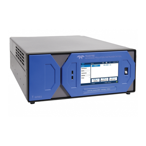
The front panel (Figure 2-1) includes two USB ports for peripheral device connections, which can be used with mouse and keyboard as alternatives to the touchscreen interface, or with flash drive for uploads/downloads (devices not included). Figure 2-1. Front Panel Layout Teledyne API T500U CAPS NO Analyzer with NumaView™ Software 083730510A DCN8172... -
Page 19: Rear Panel
ANEL Figure 2-2 shows the layout of the rear panel. Figure 2-2. Rear Panel Layout 083730510A DCN8172 Teledyne API T500U CAPS NO Analyzer with NumaView™ Software... -
Page 20: Table 2-2. Rear Panel Description
Connector for network or Internet remote communication, using Ethernet cable USB (option) Option for direct connection to laptop computer, using USB cable. Model Label Includes voltage and frequency specifications Teledyne API T500U CAPS NO Analyzer with NumaView™ Software 083730510A DCN8172... -
Page 21: Internal Chassis
NTERNAL HASSIS Figure 2-3 shows the internal chassis layout. Figure 2-3. Internal Chassis Layout 083730510A DCN8172 Teledyne API T500U CAPS NO Analyzer with NumaView™ Software... -
Page 22: Connections And Startup
AC voltage range and ensure that it is equipped with a functioning earth ground. It is important to adhere to all safety and cautionary messages. Teledyne API T500U CAPS NO Analyzer with NumaView™ Software 083730510A DCN8172... -
Page 23: Connecting Analog Outputs
I Out + through the Ground I Out - Setup>Analog I Out + Outputs menu. Ground I Out - I Out + Ground I Out - Not Available Ground Not Available 083730510A DCN8172 Teledyne API T500U CAPS NO Analyzer with NumaView™ Software... -
Page 24: Current Loop Analog Outputs (Option 41) Setup
ESD damage, refer to the manual, Fundamentals of ESD, PN 04786, which can be downloaded from our website at http://www.teledyne-api.com. Figure 2-5. Current Loop Option Installed on the Motherboard Teledyne API T500U CAPS NO Analyzer with NumaView™ Software 083730510A DCN8172... -
Page 25: Connecting The Status Outputs (Digital Outputs)
1.2V from its collector to emitter. STATUS Map the digital outputs 1 thru 8 through the Setup>Digital Outputs menu. +5V to external device Figure 2-6. Status Output Connector for Digital Outputs 083730510A DCN8172 Teledyne API T500U CAPS NO Analyzer with NumaView™ Software... -
Page 26: Connecting The Control Inputs (Digital Inputs)
(more convenient), or by a separate external 5 VDC power supply (ensures that these inputs are truly isolated). Refer to Figure 2-7. CONTROL IN CONTROL IN 5 VDC Power Supply Local Power Connections External Power Connections Figure 2-7. Energizing the Control Inputs Teledyne API T500U CAPS NO Analyzer with NumaView™ Software 083730510A DCN8172... -
Page 27: Concentration Alarm Relay (Option 61)
Ethernet interface connector to an Ethernet port. Although the analyzer is shipped with DHCP enabled by default, it should be manually configured with a static IP address. Configuration: Section 2.5.10.5 083730510A DCN8172 Teledyne API T500U CAPS NO Analyzer with NumaView™ Software... -
Page 28: Figure 2-9. Rear Panel Connector Pin-Outs For Rs-232 Mode
For RS-232 communications with data terminal equipment (DTE) or with data communication equipment (DCE) connect either a DB9-female-to-DB9-female cable (Teledyne API part number WR000077) or a DB9-female-to-DB25-male cable (Option 60A), as applicable, from the analyzer’s RS-232 port (see Figure 2-9 for connector pin assignments) to the device. -
Page 29: Figure 2-10. Default Pin Assignments For Cpu Com Port Connector (Rs-232)
Figure 2-10. Default Pin Assignments for CPU COM Port Connector (RS-232) Teledyne API offers two mating cables, one of which should be applicable for your use. P/N WR000077, a DB-9 female to DB-9 female cable, 6 feet long. Allows connection •... - Page 30 (Be aware that the CPU’s COM2 connector is not used in Multidrop) J4 on the Multidrop/LVDS PCA to J12 on the motherboard • J1 on the Multidrop/LVDS PCS to the front panel LCD • Teledyne API T500U CAPS NO Analyzer with NumaView™ Software 083730510A DCN8172...
-
Page 31: Figure 2-11. Jumper And Cables For Multidrop Mode
LEDs (RX and TX) of the COM1 connector (labeled RS232) are both lit. (Ensure you are using the correct RS-232 cables internally wired specifically for RS-232 communication; see Figure 2-10). 083730510A DCN8172 Teledyne API T500U CAPS NO Analyzer with NumaView™ Software... -
Page 32: Pneumatic Connections
The (communication) Host instrument can address only one Note instrument at a time, each by its unique ID (see step 7 above). Teledyne API recommends setting up the first link that runs Note between the Host and the first analyzer, and testing it before setting up the rest of the chain. - Page 33 • Run a leak check once the appropriate pneumatic connections have been made; check all pneumatic fittings for leaks per Section 5.4.12.1 (or Section 5.4.12.2 for detailed check if any leaking is suspected). 083730510A DCN8172 Teledyne API T500U CAPS NO Analyzer with NumaView™ Software...
-
Page 34: Critical Tubing, Pressure, Venting And Exhaust Requirements
Calibration Gas Sources: The source of calibration gas or zero air is also attached to the SAMPLE inlet, but • only when a calibration operation is actually being performed. Teledyne API T500U CAPS NO Analyzer with NumaView™ Software 083730510A DCN8172... -
Page 35: Basic Connections From Calibrator
SAMPLE inlet, but only when a calibration operation is actually being performed. ENTING Vent the output of the calibrator if calibrator not already vented. XHAUST UTLET Attach an exhaust line to the EXHAUST outlet fitting and vent outside the shelter. 083730510A DCN8172 Teledyne API T500U CAPS NO Analyzer with NumaView™ Software... -
Page 36: Pneumatic Flow Diagrams
This section shows a diagram of the basic pneumatic flow with the zero/span valves option (Figure 2-14) and with the internal zero/span Option (Figure 2-15). NEUMATIC LOW FOR ASIC ONFIGURATION Figure 2-14. Pneumatics, Basic Configuration with Zero/Span Valve Option Teledyne API T500U CAPS NO Analyzer with NumaView™ Software 083730510A DCN8172... -
Page 37: Startup, Functional Checks And Calibration
When the instrument is first started (Section 2.3.4.1), check its functionality (Section 2.3.4.3) and run an initial calibration (Section 2.3.4.4). Section 2.4 introduces the menu system, and Section 2.5 provides setup/customization instructions. 083730510A DCN8172 Teledyne API T500U CAPS NO Analyzer with NumaView™ Software... -
Page 38: Startup
Figure 2-16. Status Screens at Startup Upon any startup, this instrument should warm up for approximately one hour before reliable measurements can be taken. Figure 2-17. Home Page Example Teledyne API T500U CAPS NO Analyzer with NumaView™ Software 083730510A DCN8172... -
Page 39: Alerts: Warnings And Other Messages
Figure 2-18. Viewing Active Alerts Page If Alerts about warning conditions persist after the warm up period or after being cleared, investigate their cause using the troubleshooting guidelines in Section 0. 083730510A DCN8172 Teledyne API T500U CAPS NO Analyzer with NumaView™ Software... -
Page 40: Functional Checks
Follow the appropriate calibration instructions presented in Section 4. Teledyne API T500U CAPS NO Analyzer with NumaView™ Software 083730510A DCN8172... -
Page 41: Menu Overview
Section 2.5.9 connected to a network that is connected to the Internet. Time Zone change requires special procedures (Section 5.5). Comm View and configure network and serial communications. Section 2.5.10 083730510A DCN8172 Teledyne API T500U CAPS NO Analyzer with NumaView™ Software... -
Page 42: Home Page
Section 2.5.6 provides configuration instructions. Figure 2-20. User Interface Orientation Teledyne API T500U CAPS NO Analyzer with NumaView™ Software 083730510A DCN8172... -
Page 43: Figure 2-21. Concentration And Stability Graph (Top) And Meter Graph (Bottom)
Figure 2-21. Concentration and Stability Graph (top) and Meter Graph (bottom) 083730510A DCN8172 Teledyne API T500U CAPS NO Analyzer with NumaView™ Software... -
Page 44: Dashboard
2.5.3 provides configuration instructions). If there is a graphing icon in the upper right corner of a parameter, pressing that parameter displays a live plot of its readings as in Figure 2-22. Figure 2-22. Dashboard Page Teledyne API T500U CAPS NO Analyzer with NumaView™ Software 083730510A DCN8172... -
Page 45: Alerts
To clear Alerts from the Active Alerts page, either check individual boxes to choose specific Alerts, or check the Select All box to choose all Alerts, then press the Clear Selected button. 083730510A DCN8172 Teledyne API T500U CAPS NO Analyzer with NumaView™ Software... -
Page 46: Calibration
Figure 2-25. Utilities>Alerts Log of Active and Past Alerts and Events ALIBRATION The Calibration menu is used for zero/span/multipoint calibrations and for external calibration with valve options installed. Calibration procedures are presented in Section 4. Teledyne API T500U CAPS NO Analyzer with NumaView™ Software 083730510A DCN8172... -
Page 47: Utilities
Sample mode after conducting a calibration. ETUP The Setup menu is used to configure the instrument’s various features, functions, and data log. Section 2.5 provides details for the menus under Setup. 083730510A DCN8172 Teledyne API T500U CAPS NO Analyzer with NumaView™ Software... -
Page 48: Setup Menu: Features/Functions Configuration
Sections 2.5.1.1 and 2.5.1.2 providing additional details. To transfer captured instrument data to a flash drive see Section 2.5.1.3. Figure 2-26. Datalog Configuration, New Log Page Figure 2-27. Datalog Configuration, Existing Log Teledyne API T500U CAPS NO Analyzer with NumaView™ Software 083730510A DCN8172... -
Page 49: Figure 2-28. Creating A New Data Log
Figure 2-28. Creating a New Data Log The parameters available in the list of Log Tags include the names of Events configured in the Events page (Section 2.5.2). 083730510A DCN8172 Teledyne API T500U CAPS NO Analyzer with NumaView™ Software... -
Page 50: Configuring Trigger Types: Periodic
Periodic Trigger requires an interval that is set to number of minutes and a start time that is set to date and clock time. Figure 2-29. Datalog Periodic Trigger Configuration Teledyne API T500U CAPS NO Analyzer with NumaView™ Software 083730510A DCN8172... -
Page 51: Configuring Trigger Types: Conditional
2. Select all or define a period from which to download the collected data. 3. Press the Download button, and when complete, as indicated in the Status field, press the Done button (changed from “Cancel”) and remove the flash drive. 083730510A DCN8172 Teledyne API T500U CAPS NO Analyzer with NumaView™ Software... -
Page 52: Setup>Events
Home>Setup>Events menu (Figure 2-32). Press ADD to create a new Event (refer to Figure 2-33 for details), or select an existing Event to either Edit or Delete it (Figure 2-35). Teledyne API T500U CAPS NO Analyzer with NumaView™ Software 083730510A DCN8172... -
Page 53: Figure 2-33. Event Configuration
Event state. Non-latching allows the entry in the Active Alerts screen and the internal Event state to continuously update based on the Event criteria, requiring no user interaction to clear the Alert or Event state). 083730510A DCN8172 Teledyne API T500U CAPS NO Analyzer with NumaView™ Software... -
Page 54: Editing Or Deleting Events
Select an Event from the list (Figure 2-32) and press the Edit button to view or edit the details (Figure 2-34), or press the Delete button to delete the Event. Figure 2-35. Edit or Delete an Event Teledyne API T500U CAPS NO Analyzer with NumaView™ Software 083730510A DCN8172... -
Page 55: Using Events As Triggers For Data Logging
Tags of the Datalog Configuration page. The Data Logger is presented in Section 2.5.1. >D ETUP ASHBOARD Figure 2-36. Dashboard Display and Configuration >A ETUP WITH ALVE PTION Auto Cal is available with installed valve options (see Section 4.3). 083730510A DCN8172 Teledyne API T500U CAPS NO Analyzer with NumaView™ Software... -
Page 56: Setup>Vars
Disable or activate the pump without cycling the instrument power. Range Mode Controls range mode, single (SNGL) or dual (DUAL). (When set to DUAL, ensure that Max Concentration Range has been set). System Hours Total system runtime hours Teledyne API T500U CAPS NO Analyzer with NumaView™ Software 083730510A DCN8172... -
Page 57: Setup>Homescreen
Setup>Homescreen menu or from Home page using the configuration icon (Figure 2-37). Figure 2-37. Homescreen Configuration An orientation to the Homescreen was presented in Section 2.4.1, including Figure 2-20 and Figure 2-21. 083730510A DCN8172 Teledyne API T500U CAPS NO Analyzer with NumaView™ Software... -
Page 58: Setup>Digital Outputs
Go to the Utilities>Diagnostics>Digital Outputs menu to change the state (ON/OFF) of individual digital outputs. Figure 2-38. Digital Outputs Setup Teledyne API T500U CAPS NO Analyzer with NumaView™ Software 083730510A DCN8172... -
Page 59: Setup>Analog Outputs
Allow Overrange: check to allow a ± 5% over-range; uncheck to disable over-range if • the recording device is sensitive to excess voltage or current. 083730510A DCN8172 Teledyne API T500U CAPS NO Analyzer with NumaView™ Software... -
Page 60: Figure 2-40. Analog Outputs Group Calibration Screen
While these are the physical limits of the current loop modules, typical applications use 2-20 mA or 4-20 mA for the lower and upper limits. For manual calibration adjustments, see Section 2.5.8.1 for voltage and Section 2.5.8.2 for current. Teledyne API T500U CAPS NO Analyzer with NumaView™ Software 083730510A DCN8172... -
Page 61: Manual Calibration Of Voltage Range Analog Outputs
90 mV ±0.001V 0.02 mV 1 VDC ±0.001V 900 mV ±0.001V 0.24 mV 5 VDC ±0.002V 4500 mV ±0.003V 1.22 mV 10 VDC ±0.004V 4500 mV ±0.006V 2.44 mV 083730510A DCN8172 Teledyne API T500U CAPS NO Analyzer with NumaView™ Software... -
Page 62: Manual Adjustment Of Current Range Analog Outputs
Figure 2-4 for pin assignments and diagram of the analog output connector). This allows the use of a voltmeter connected across the resistor to measure converter output as VDC or mVDC. Teledyne API T500U CAPS NO Analyzer with NumaView™ Software 083730510A DCN8172... -
Page 63: Setup>Instrument
When an instrument is connected to a network that is connected to the Internet, follow the instructions on this Remote Update page to check for and activate software/firmware updates. (Also refer to Section 5.3). 083730510A DCN8172 Teledyne API T500U CAPS NO Analyzer with NumaView™ Software... -
Page 64: Setup>Comm (Communications)
(? CR). Stop bits Select either 0 or 1 stop bit (typically set in conjunction with Parity and Data bits). Teledyne API T500U CAPS NO Analyzer with NumaView™ Software 083730510A DCN8172... -
Page 65: Tcp Port1
(DHCP). Most users will want to configure the instrument with a static IP address: click the Static radio button to manually assign a static IP address (consult your network administrator, and see Table 2-14 for information). Figure 2-45. Communications Configuration, Network Settings 083730510A DCN8172 Teledyne API T500U CAPS NO Analyzer with NumaView™ Software... -
Page 66: Table 2-14. Lan/Ethernet Configuration Properties
A string of numbers very similar to the Instrument IP address (e.g. Default 192.168.76.1.) that is the address of the computer used by your LAN and serves Gateway as a router to access the Internet or another network. Teledyne API T500U CAPS NO Analyzer with NumaView™ Software 083730510A DCN8172... -
Page 67: Transferring Configuration To Other Instruments
7. When the Status field indicates that the USB drive has been detected, press the “Upload Configuration to Instrument” Start button. 8. When the Status field indicates that the upload is complete, remove the flash drive. 083730510A DCN8172 Teledyne API T500U CAPS NO Analyzer with NumaView™ Software... -
Page 68: Communications And Remote Operation
RS232 on instrument rear panel) and/or COM2 (labeled COM2 on instrument rear panel) for communication modes, baud rate and serial communications. If using a USB option communication connection, setup requires that the instrument’s baud rate and personal computer baud rate match. Teledyne API T500U CAPS NO Analyzer with NumaView™ Software 083730510A DCN8172... -
Page 69: Serial Communication: Rs-232
A code-activated switch (CAS), can also be used on either port to connect typically between 2 and 16 send/receive instruments (host computer(s) printers, data loggers, analyzers, monitors, calibrators, etc.) into one communications hub. Contact Teledyne API Sales (front cover, this manual) for more information on CAS systems. -
Page 70: Communications Protocols
MODBUS registers are provided in Appendix A. MODBUS These instructions assume that the user is familiar with MODBUS communications, and provide minimal information to get started. Please refer to the Teledyne API MODBUS manual, PN 06276, and to www.modbus.org for MODBUS communication protocols. Minimum Requirements: Instrument firmware with MODBUS capabilities installed •... -
Page 71: Figure 3-2. Modbus Via Serial Communication (Example)
Setup>Vars>Instrument ID menu. Next, for the settings to take effect, power off the analyzer, wait 5 seconds, and power it on again. 083730510A DCN8172 Teledyne API T500U CAPS NO Analyzer with NumaView™ Software... -
Page 72: Hessen
Create a unique identification number for each instrument in Important the multidrop chain via the Setup>Vars>Instrument ID menu. The Hessen protocol is not strictly defined; therefore, while Teledyne API’s application is completely compatible with the protocol itself, it may be different from implementations by other companies. -
Page 73: Hessen Settings Configuration
ESPONSE Set the response mode under Hessen Response Mode, referring to Table 3-2 for descriptions. Table 3-2. Teledyne API's Hessen Protocol Response Modes MODE ID MODE DESCRIPTION This is the default setting. Reponses from the instrument are encoded as the traditional command format. -
Page 74: Hessen Gas List
Be careful not to assign conflicting flags to the same bit as each status bit will be triggered if any of the assigned flags is active. HESSEN GAS LIST In the T500U there is no Hessen Gas List to configure as there is only one gas, NO2, the Hessen ID for which is 213. Teledyne API T500U CAPS NO Analyzer with NumaView™... -
Page 75: Calibration
See Section 4.2.1 for instructions for initial calibration of the analyzer in its base configuration. See Section 4.2.2 for information regarding setup and calibration of the analyzer with • Z/S Valve options. 083730510A DCN8172 Teledyne API T500U CAPS NO Analyzer with NumaView™ Software... -
Page 76: Zero Air
Alternatively, if a calibrator is available that is a trusted source of stable ozone, e.g., Teledyne API Model T700U with certified photometer, it is possible to use that O output directly to obtain the NO concentration. -
Page 77: 2 Permeation Tubes
ERMEATION UBES Teledyne API offers an optional internal span gas generator that utilizes an NO permeation tube as a span gas source. The accuracy of these devices is only about ±5%. Whereas this may be sufficient for quick, daily calibration checks, we recommend using certified NO gases for accurate calibration. -
Page 78: Calibration And Check Procedures For Basic Configuration
Stability falls below 1.0 PPB (either in the gas graph or in the Dashboard). Otherwise, follow the steps presented in Sections 4.2.1.1 and 4.2.1.2. Figure 4-1. Multi-Point Calibration Page Teledyne API T500U CAPS NO Analyzer with NumaView™ Software 083730510A DCN8172... -
Page 79: Zero Calibration Check And Actual Calibration
3. Press the Stop button and return to Home screen. 4. In the Dashboard, check and record the Slope(s) and the Offset(s). (See Table Section 4.4, Calibration Quality Analysis, expected/acceptable values). 083730510A DCN8172 Teledyne API T500U CAPS NO Analyzer with NumaView™ Software... -
Page 80: Calibration And Check Procedures With Valve Options Installed
The remote calibration contact closures may be activated in any order. • It is recommended that contact closures remain closed for at least 10 minutes to establish a reliable reading. Teledyne API T500U CAPS NO Analyzer with NumaView™ Software 083730510A DCN8172... -
Page 81: Automatic Zero/Span Cal/Check (Auto Cal)
Table 4-1 and Table 4-2 show how to set up the operating states of each calibration or check, and Table 4-3 shows how to program the execution of each. Figure 4-3. Auto Cal Page 083730510A DCN8172 Teledyne API T500U CAPS NO Analyzer with NumaView™ Software... -
Page 82: Table 4-1. Auto Cal States
Zero Low High Calibrate For each sequence, there are four parameters that control operational details: Date, Time (both in the Start field), Interval, and Duration, as presented in Table 4-3. Teledyne API T500U CAPS NO Analyzer with NumaView™ Software 083730510A DCN8172... -
Page 83: Calibration Quality Analysis
Otherwise, refer to the troubleshooting Section 5.7.6. Table 4-4. Calibration Data Quality Evaluation FUNCTION MINIMUM VALUE OPTIMUM VALUE MAXIMUM VALUE SLOPE -0.800 1.000 1.200 OFFSET -10 ppb 0.0 ppb 10.0 ppb 083730510A DCN8172 Teledyne API T500U CAPS NO Analyzer with NumaView™ Software... -
Page 84: Epa Protocol Calibration
Government Publishing Office at http://www.gpo.gov/fdsys/) and with Quality Assurance Guidance documents (available on the EPA website: http://www3.epa.gov/ttn/amtic/qalist.html). Give special attention to specific regulations regarding the use and operation of ambient NO analyzers (chemiluminescence). Teledyne API T500U CAPS NO Analyzer with NumaView™ Software 083730510A DCN8172... -
Page 85: Maintenance And Service
MAINTENANCE AND SERVICE Although the T500U analyzer requires little service, a few simple procedures should be performed regularly to ensure that the T500U continues to operate accurately and reliably over its lifetime. In general, the exterior can be wiped down with a lightly damp cloth. -
Page 86: Predictive Diagnostics
The following table, checked weekly, can be used as a basis for taking action as these values change with time. Teledyne API T500U CAPS NO Analyzer with NumaView™ Software 083730510A DCN8172... -
Page 87: Operational Health Checks
Figure 5-1: Report Generation Page The report can also be set to generate periodically and sent to a Web services “cloud” where it is available for viewing by Teledyne API technical support personnel. Set this function with two Vars: Setup>Vars>Upload Report to Cloud: set to True. -
Page 88: Software/Firmware Updates
Figure 5-3. Manual Update Page (and other utilities) 3. Insert a flash drive into a front panel USB port and wait for the Status field to indicate that the drive has been detected. Teledyne API T500U CAPS NO Analyzer with NumaView™ Software 083730510A DCN8172... - Page 89 6. When complete, as indicated in the Status field, press the Done button, which replaces the Cancel button, and remove the flash drive. 7. Power off and restart the instrument to complete the new firmware installation. 083730510A DCN8172 Teledyne API T500U CAPS NO Analyzer with NumaView™ Software...
-
Page 90: Time Zone Changes
6. After the Time Zone is implemented first (Steps 1 through 5), then other changes to the date and/or time can be made, and recycling the power is not necessary. Figure 5-4. Time Zone Change Requirements Teledyne API T500U CAPS NO Analyzer with NumaView™ Software 083730510A DCN8172... -
Page 91: Hardware Maintenance Procedures
4. Remove the AREF filter assembly from the mounting brackets. 5. Remove the fittings that connect the two filters to one another. 6. Install replacement filters and reconnect AREF assembly and fittings in reverse order. 083730510A DCN8172 Teledyne API T500U CAPS NO Analyzer with NumaView™ Software... -
Page 92: Replacing The Internal Pump
13. Use caution when fastening the new pump into position to ensure that no wires or pneumatic tubes get pinched under the pump mounting bracket. Figure 5-7. Internal Pump Teledyne API T500U CAPS NO Analyzer with NumaView™ Software 083730510A DCN8172... -
Page 93: Changing The Internal Span Gas Generator Permeation Tube
Do not ship the instrument without removing the permeation tube. The tube continues to emit NO even at room temperature and will contaminate the entire instrument. 083730510A DCN8172 Teledyne API T500U CAPS NO Analyzer with NumaView™ Software... -
Page 94: Checking For Pneumatic Leaks
7. Clean surfaces from soap solution, reconnect the sample and pump lines and replace the instrument cover. 8. Restart the analyzer. Teledyne API T500U CAPS NO Analyzer with NumaView™ Software 083730510A DCN8172... -
Page 95: Performing A Sample Flow Check
Do not drop tools into the analyzer or leave them after your procedures. Do not short or touch electric connections with metallic tools while operating inside the analyzer. Use common sense when operating inside a running analyzer. 083730510A DCN8172 Teledyne API T500U CAPS NO Analyzer with NumaView™ Software... -
Page 96: Fault Diagnosis With Alerts
It should be noted that if more than two or three warning Alerts occur at the same time, it is often an indication that some fundamental sub-system (power supply, relay PCA, motherboard) has failed rather than an indication of the specific failures referenced by the warnings. Teledyne API T500U CAPS NO Analyzer with NumaView™ Software 083730510A DCN8172... -
Page 97: Table 5-3. Warning Alerts, Fault Conditions And Possible Causes
Failed +5 VDC power Fatal Error caused software to restart Loose connector/wiring Clears the next time successful zero calibration is performed. Clears the next time successful span calibration is performed. 083730510A DCN8172 Teledyne API T500U CAPS NO Analyzer with NumaView™ Software... -
Page 98: Fault Diagnosis With Dashboard Functions
Many of the components and functions that are normally under algorithmic control of • the CPU can be manually exercised. The technician can directly control the signal level Analog and Digital Output signals. • Teledyne API T500U CAPS NO Analyzer with NumaView™ Software 083730510A DCN8172... -
Page 99: Using The Analog Output Channels
If the front panel displays properly but DS5 does not flash, then the program files have become corrupted, contact Teledyne API's Technical Support Department (see Section 5.9) because it may be possible to recover operation of the analyzer. If after 30 –... -
Page 100: Figure 5-9. Relay Pca Status Leds Used For Troubleshooting
Valve broken or stuck, valve driver chip broken LED ROW 2 Internal span gas generator Yellow Heater broken, thermistor broken perm tube heater Green Dual span select valve Valve broken or stuck, valve driver chip broken Teledyne API T500U CAPS NO Analyzer with NumaView™ Software 083730510A DCN8172... -
Page 101: Calibration Problems
4. Confirm the sample pressure, sample temperature, and sample flow readings are correct and steady. 5. Verify that the sample filter element is clean and does not need to be replaced. 083730510A DCN8172 Teledyne API T500U CAPS NO Analyzer with NumaView™ Software... -
Page 102: Inability To Span - Deactivated Span Button
If a mass flow calibrator is used and the flow is less than 10% of the full scale flow on either flow controller, you may need to purchase lower concentration standards. Teledyne API T500U CAPS NO Analyzer with NumaView™ Software 083730510A DCN8172... -
Page 103: Discrepancy Between Analog Output And Display
Dirty or plugged sample filter or sample lines. • Sample inlet line is too long. • Dirty or plugged flow restrictor. Check flows, pressures and, if necessary, change restrictor. 083730510A DCN8172 Teledyne API T500U CAPS NO Analyzer with NumaView™ Software... -
Page 104: Aref Warnings
This section describes how to determine if a certain component or subsystem is actually the cause of the problem being investigated. Teledyne API T500U CAPS NO Analyzer with NumaView™ Software 083730510A DCN8172... -
Page 105: Ac Main Power
Table 5-6. DC Power Test Point and Wiring Color Codes NAME TEST POINT# COLOR DEFINITION DGND Black Digital ground AGND Green Analog ground +15V Blue -15V Yellow +12R Purple 12 V return (ground) line +12V Orange 083730510A DCN8172 Teledyne API T500U CAPS NO Analyzer with NumaView™ Software... -
Page 106: I 2 C Bus
Assuming that there are no wiring problems and that the DC power supplies are operating properly, the display screen should light and show the splash screen and other indications of its state as the CPU goes through its initialization process. Teledyne API T500U CAPS NO Analyzer with NumaView™ Software 083730510A DCN8172... -
Page 107: Relay Pca
Although not all test points (TP) on the DAQ are used, if the values for TP14 through TP21, TP23 and TP24 do not come back as expected (Figure 5-11), contact Teledyne API Technical Support for a replacement. Figure 5-11. DAQ PCA Test Points and LEDs... -
Page 108: Motherboard
5. Alternately turn on and off the output noting the voltage on the voltmeter. • It should vary between 0 volts for ON and 5 volts for OFF. Teledyne API T500U CAPS NO Analyzer with NumaView™ Software 083730510A DCN8172... -
Page 109: Cpu
RS-232 T ENERAL ROUBLESHOOTING Teledyne API's analyzers use the RS-232 communications protocol to allow the instrument to be connected to a variety of computer-based equipment. Problems with RS-232 connections usually center around five general areas: Incorrect cabling and connectors. See Section 2.3.1.7 under RS-232 Connection for •... -
Page 110: Internal Span Gas Generator And Valve Options
At about 30° C, the signal should be around 1500 mV. • To check the accuracy of the sensor, use a calibrated external thermometer/ • temperature sensor to verify the accuracy of the box temperature by: Teledyne API T500U CAPS NO Analyzer with NumaView™ Software 083730510A DCN8172... -
Page 111: Service Procedures
Regular maintenance procedures are discussed in Section 5.5 Note and are not listed here). Also, there may be more detailed service notes for some of the below procedures. Contact Teledyne API's Technical Support Department. WARNING – ELECTRICAL SHOCK HAZARD Unless the procedure being performed requires the instrument... -
Page 112: Removing / Replacing The Relay Pca From The Instrument
The Relay retainer plate installed on the relay PCA covers the lower right mounting screw of the relay PCA. Therefore, when removing the relay PCA, the retainer plate must be removed first. Teledyne API T500U CAPS NO Analyzer with NumaView™ Software 083730510A DCN8172... -
Page 113: Frequently Asked Questions
Figure 5-14. Relay PCA Mounting Screw Locations FREQUENTLY ASKED QUESTIONS The following list was compiled from the Teledyne API's Technical Support Department’s ten most commonly asked questions relating to the analyzer. QUESTION ANSWER Why does the ENTR button Sometimes the ENTR button will disappear if you select a setting that is... -
Page 114: Technical Assistance
Teledyne API Technical Support 9970 Carroll Canyon Road San Diego, California 92131-1106 USA Toll-free Phone: +1 800-324-5190 Phone: +1 858-657-9800 Fax: +1 858-657-9816 Email: api-techsupport@teledyne.com Website: http://www.teledyne-api.com/ Teledyne API T500U CAPS NO Analyzer with NumaView™ Software 083730510A DCN8172... -
Page 115: Principles Of Operation
(A = Absorbance, ε = Molar absorptivity, l = Mean path Length, c = concentration) The CAPS method employed in the T500U is unique in that it applies this fundamental optical absorption law in the frequency domain, rather than using relative changes in light intensity as the primary signal. -
Page 116: Figure 6-1. T500U Optical Absorption Cell
DETECTOR 2X 450 nm BANDPASS MIRRORS FILTER T500U OVEN Figure 6-1. T500U Optical Absorption Cell LED ON Absorbing Gas LED OFF ϑ Figure 6-2. Phase Shift Representation of Increased Concentration of NO (Black = LED State, Blue = Light build up in the absence of NO... -
Page 117: Glossary
Disk On Module, a 44-pin IDE flash drive with up to 128MB storage capacity for instrument’s firmware, configuration settings and data Disk Operating System DRAM Dynamic Random Access Memory DR-DOS Digital Research DOS 083730510A DCN8172 Teledyne API T500U CAPS NO Analyzer with NumaView™ Software... - Page 118 Teflon ® Programmable Logic Controller, a device that is used to control instruments based on a logic level signal coming from the analyzer Programmable Logic Device Phase Lock Loop Teledyne API T500U CAPS NO Analyzer with NumaView™ Software 083730510A DCN8172...
- Page 119 Variables, the variable settings of the instrument VARS Voltage-to-Frequency Zero / Span 083730510A DCN8172 Teledyne API T500U CAPS NO Analyzer with NumaView™ Software...
-
Page 120: Appendix A - Modbus Registers
External analog input 3 slope eng unit /V External analog input 3 offset eng unit External analog input 4 value Volts External analog input 4 slope eng unit /V Teledyne API T500U CAPS NO Analyzer with NumaView™ Software 083730510A DCN8172... - Page 121 Sample pressure warning System reset warning Rear board communication warning Relay board communication warning Front panel communication warning Analog calibration warning Dynamic zero warning Dynamic span warning Invalid concentration 083730510A DCN8172 Teledyne API T500U CAPS NO Analyzer with NumaView™ Software...
- Page 122 Refer to the Calibration section of this manual for running a calibration check without changing slope and offset vs actual calibration. Concentration alarm option. Hessen option. Manifold heater option. IZS option. External analog input option. Teledyne API T500U CAPS NO Analyzer with NumaView™ Software 083730510A DCN8172...
- Page 123 Appendix B Analog Status Control RS-232 RS-485 Out J1020 Out J1017 In J1004 J1013 J1010 & 1011 AC POWER SWITCH AC POWER Motherboard ENTRANCE CN5 CN4 058021400 CPU 06724 CP34 J107 J106 J106 PUMP 078510000 Thrm/Heater PCA, Caps Daq 076730000 (+5, ±15) Assy LED Preamp/Mixr...
Need help?
Do you have a question about the T500U and is the answer not in the manual?
Questions and answers