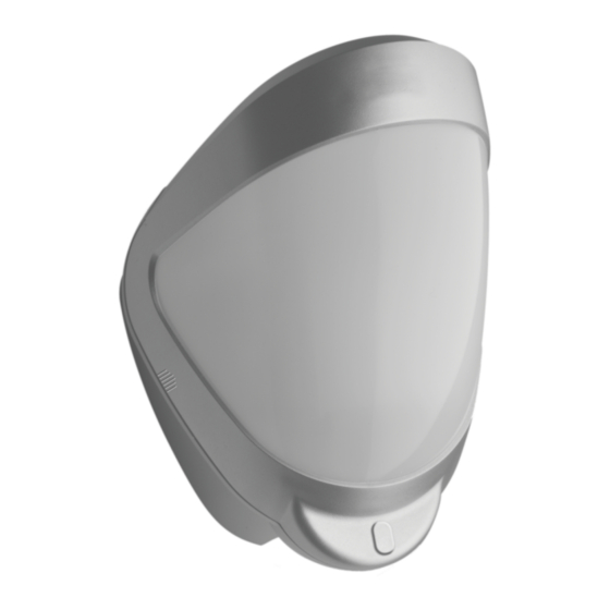
Summary of Contents for UTC Fire and Security interlogix DI601AM
- Page 1 DI601AM Outdoor PIR/AM Detector Installation Sheet Figure 1 Figure 2 Figure 3...
- Page 2 Figure 4 Figure 5 Figure 6 Figure 7 Figure 8...
- Page 3 Figure 9 Note: EN50131-2-2 Grade 3 compliance requires 3m mounting Long range 30m section height and 0º adjustment, or 1.5m mounting height and -2º adjustment. Short/ medium range 6m to 20m section 0° 10 12 14 16 18 20 22 24 26 28 30m Figure 10 Note: This setup has not been tested...
- Page 4 Figure 12 MASK THIS SECTION OFF FOR CURTAIN COVERAGE APPLICATIONS 45° 8 10 12 14 16m Figure 14 Figure 13 70° 70° 2 4 6 8 10 12 14 16 18 20 22 24 26 28 30m...
- Page 5 Figure 15 Legend: J TEOL: Jumper to enable TEOL. Figure 15a, Item 1 Ja: Jumper to set EOL resistor value for alarm. Figure 15a, item 2 Jt: Jumper to set EOL resistor value for standby. Figure 15a, item 3 alarm n/c Jf: Jumper to set EOL resistor value for fault.
- Page 6 Figure 16 Single zone TEOL Calculation Event Default (Ohm) CALCULATION TAMPER (SHORT) CLOSED CIRCUIT STANDBY ALARM Rt + Ra FAULT 14K7 Rt + Rf ANTI MASK 19K4 Rt + Ra + Rf TAMPER (OPEN) Inf. OPEN CIRCUIT EXAMPLE USING 4K7 TAMPER, 4K7 ALARM AND 10K FAULT/A-M RESISTORS ALSO TEOL JUMPER SELECTED REMOVE ALL JUMPERS FOR ISOLATED OUTPUTS Single zone DEOL Calculation...
-
Page 7: En: Installation Sheet
3.Use a razor knife to open a rubber seal to allow the cabling EN: Installation Sheet into the unit (see Figure 4). Feed standard eight-core or 12-core alarm cable though the wall and directly into the cable entry. Bare the wires and connect to the top PCB terminal block Package (Figure 15) The package contains:... -
Page 8: Multibeam Alignment And Masking
4, 5 TEOL Triple End-of-Line Curtain cover- Figure resistors age [2] 5, 7 DEOL Double End-of- [1]Black area should be masked for pet alley applications up to Line resistors 30 meters. 5, 6 ALARM N/C Alarm relay, [2]Black area should be masked for curtain coverage normally closed applications. -
Page 9: Resetting Options
To change any of DI601AM settings: CAUTION The range of the detector increases without the protective front Note: Only the top PCB red LED is used in programming the cover. Therefore the front cover must be fitted to establish detector. the correct beam pattern. -
Page 10: Specifications
Specifications Regulatory information Manufacturer UTC Fire & Security Americas Detection range Programmable: 10 m, 20 m Corporation, Inc. or 30 m 1275 Red Fox Rd., Arden Hills, MN 55112-6943, USA Coverage 10 to 70° detection angle, 30 Authorized EU manufacturing x 24 m coverage max.


Need help?
Do you have a question about the interlogix DI601AM and is the answer not in the manual?
Questions and answers