Table of Contents
Advertisement
Quick Links
CAUTION
1. The wiring procedures in this manual are
intended to ensure proper functioning of the
device under normal conditions.
because of the many variations in wiring
codes and regulations, total compliance to
these ordinances cannot be guaranteed. Be
certain that all wiring complies with applicable
regulations that relate to the installation of
electrical equipment in a hazardous area. If in
doubt, consult a qualified official before wiring
the system.
2. The
devices
in
semiconductor devices that are susceptible
to damage by electrostatic discharge.
electrostatic charge can build up on the skin
and discharge when an object is touched.
Therefore, use caution when handling the
device, taking care not to touch the terminals
or electronic components. Observe normal
precautions for handling electrostatic sensitive
devices.
3. The fault detection circuitry does not monitor the
operation of external response equipment or the
external wiring to these devices. It is important
that these devices be checked periodically to
ensure that they are operational.
SYSTEM DESCRIPTION
Det-Tronics Flame Detection/Releasing System (FDRS)
combines flame detection, signal processing, relay and
detonation output devices into a single system (Figure
5). In addition to the Det-Tronics flame detectors, the
FDRS accepts inputs from devices such as heat and
smoke sensors, and manual trip stations. The FDRS
1.3
©
1.3
Detector Electronics Corporation 2004
However,
this
system
contain
An
Flame Detection / Releasing System
with X-Series Flame Detectors
provides alarm and fault relay outputs, a detonator
output that provides high speed output for direct
connection to a deluge valve, and extinguishing agent
release signals for connection to a releasing panel. The
system includes:
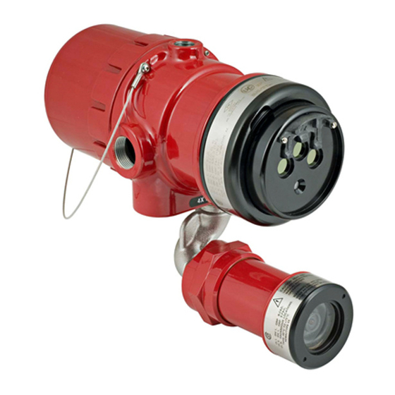
X2200 UV Flame Detector with Pulse Output
X9800 IR Flame Detector with Pulse Output
X5200 UV/IR Flame Detector with Pulse Output
X3301 Multispectrum IR Flame Detector with Pulse Output
R7404 Standard Controllers
(system capacity up to 4 controllers, up to 8 flame
detectors per controller)
R7494 Flame Controllers (system capacity up to 4
controllers, up to 8 flame detectors per controller)
R6006 Relay Output Module
R1425 Detonator Module
Power Supply/Battery Charger and Battery Backup
W2400 Ground Fault Monitor Module
BFD Battery Failure Detector
NEMA Rated Enclosure
System Drawings
The FDRS is FM approved per ANSI/NFPA-72 National
Fire Alarm Code:
1. Equivalent to Class B, Style A initiating device circuit
(IDC) when detector is installed in single detector
configuration.
2. Equivalent to Class A, Style D initiating device circuit
(IDC) when detectors are installed in a redundant
configuration (two detectors monitor exactly the
same area). The configuration continues to provide
area coverage via the second detector in the event
a single circuit fault disables one of the detectors/
circuits.
1
INSTRUCTIONS
95-8574
3/04
95-8574
Advertisement
Table of Contents

Related Manuals for UTC Fire and Security Det-Tronics X Series


Summary of Contents for UTC Fire and Security Det-Tronics X Series
- Page 1 INSTRUCTIONS Flame Detection / Releasing System with X-Series Flame Detectors CAUTION provides alarm and fault relay outputs, a detonator output that provides high speed output for direct 1. The wiring procedures in this manual are intended to ensure proper functioning of the connection to a deluge valve, and extinguishing agent release signals for connection to a releasing panel.
-
Page 2: Major Component Descriptions
Figure 1A—X3301 Multispectrum IR Flame Detector Figrue 1B—X2200 UV Flame Detector SySTEm POwER aND wIRINg X Series Flame Detectors include the following: The R7404, R7494, R6006, R1425 and W2400 are all X3301 Multispectrum IR Detector — See Figure 1A. mounted within a mounting rack that is located within a NEMA Rated enclosure. - Page 3 automatic Oi R7494 CONTROLLER The detector includes the Automatic Optical Integrity The R7494 Controller is also used with all X-Series (o i ) feature — a calibrated performance test that is Pulse Output Flame Detectors. Up to 8 detectors can automatically performed once per minute to verify be used with each controller, with up to 4 controllers complete detector operation capabilities.
- Page 4 RELAY MODULE RELAY MODULE RELAYS RELAYS RELAY ALARM FAULT ACCEPT RELAY STATUS RELAY STATUS SELECT TEST SELECT TEST SYSTEM SYSTEM STATUS FAULT INHIBIT STATUS FAULT INHIBIT LAMP TEST LAMP TEST POWER POWER TEST TEST RESET RESET NORMAL NORMAL R6006A, C R6006B, D RED ALARM RELAY LED, NORMALLY OFF—BLINKS WHEN RELAY ENERGIZED, ON (STEADY) WHEN RELAY DE-ENERGIZED, (ALARM ACCEPT) SELECT/ALARM ACCEPT BUTTON—IN NORMAL MODE, DE-ENERGIZES ALARM RELAY –...
-
Page 5: System Operation
environmental and operating conditions. As a result, battery failures can occur, decreasing battery capacity and the ability to provide the necessary system operating power. The BFD monitors the overall battery voltage and the mid-point voltage of each battery string in the system. It reports an alarm if the monitored voltage is outside the acceptable limits, indicating a battery problem. -
Page 6: Specifications
SPECIFICATIONS INSTALLATION A partial list of system specifications is provided here. A set of System Drawings is supplied with each For detailed specifications, refer to the applicable system and is specific to that system. These manual for the device or contact the factory. drawings detail system wiring, terminal assignments, enclosure dimensions, standard symbols and wiring specifications. - Page 7 table 2—Standby Current Requirements at +24 vdc Device Type No. of Devices Standby Current Total Current for Device Type X2200 0.104 X9800 0.087 X5200 0.116 X3301 0.167 R7404A/B 0.062 R7494 0.063 R6006 0.104 R1425 0.104 w2400 0.015 0.160 Resistor network load 0.012 heat Sensor Manual Pull...
-
Page 8: Troubleshooting And Maintenance
table 4—Back-Up Battery Requirements for Deluge and Pre-Action Applications Standby Current: Standby time: Standby Amp hours: __________ 90 hours __________ Alarm Current: 10 Minute Alarm Alarm Amp hours: __________ time: 0.17 hour __________ Sum of Standby and Alarm Amp hours 10% Safety Factor total Battery Amp hour Requirement table 5—Back-up Battery Requirements for Automatic Release of extinguishing Systems except Deluge... -
Page 9: Ordering Information
ORDERING INFORMATION 4. Loosen the captive screw at the bottom of the front panel of the module and slide it out of the mounting For assistance in ordering, please contact: rack. Detector Electronics Corporation 5. Return to the factory for repair as instructed in the 6901 West 110th Street “Repair and Return”... - Page 10 95-8574...
- Page 11 95-8574...
Need help?
Do you have a question about the Det-Tronics X Series and is the answer not in the manual?
Questions and answers