Advertisement
Quick Links
www.norix.com ● TEL 800 234-4900
Assembly Notes:
Norix is not responsible for any damage due to improper installation. If your shipment does not match the parts list, please contact Norix Customer Service at 800-234-4900.
Norix reserves the right to modify design specifications at any time without an obligation to owners of previously sold products.
___________________________________________________________________________________________________________________________________________________________________________________________________
Important Note: For a successful installation, careful and accurate
layout of the anchor brackets is a must. Read through the
instructions first and familiarize yourself with all of the steps. If you
have any questions, please call Norix Customer Care before
proceeding. Norix is not responsible for damage to components
due to improper installation.
Security Caulk is highly recommended to help seal gaps and
secure the furniture in place. Apply caulk to clean surfaces.
Anchor hardware: Please familiarize yourself with the anchoring components as shown below.
If any components are missing, contact Norix Customer Care before proceeding.
Floor Anchor Bracket (2)
011-058
Drill Guide, Pin (1)
011-063
Concrete Anchor,
5/16" X 2" L (4)
024-024
Rev. C - 10/20/20
091-989
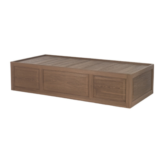
Prodigy Bed
Assembly Instructions
Model Number
PRD100
Anchor Tab, Straight (2)
011-059
5/8" Drill Bit (1)
029-944
Guide Tube (2)
029-941
Patents Pending
Low RPM Variable Speed Drill
Pin-in-Torx® Driver Bit T-40 (provided)
Anchor Hook, Left (1)
011-067
Screw, 5/16-18 X 5/8" L, BH (2)
Shim (4)
060-197
Pin Extractor Tool (1)
011-066
Tools Needed
Hammer Drill
5/16" masonry drill bit
5/8" Drill Bit (provided)
Anchor Hook, Right (1)
011-068
021-118
Ball Lock Pin (2)
002-027
Page 1 of 13
Advertisement

Related Manuals for norix PRD100


Summary of Contents for norix PRD100
- Page 1 Assembly Notes: Norix is not responsible for any damage due to improper installation. If your shipment does not match the parts list, please contact Norix Customer Service at 800-234-4900. Norix reserves the right to modify design specifications at any time without an obligation to owners of previously sold products.
- Page 2 See appropriate section depending on location of installation: Section I: Mid-wall installation with long side against wall, page 2 Section II: Mid-wall installation with short side against wall, page 6 Section III: Corner installation, page 10 Section I Mid-wall installation with long side against wall: open areas Note: In this installation, the Left and Right Anchor Hooks will not be used.
- Page 3 6. Carefully measure 3" inward from the first line Make new lines and mark a second line. Repeat at the other end. 3'' inward 3" 7. Place Floor Anchor Bracket with holes centered on centerline as shown, and vertical face aligned with the line as shown.
- Page 4 10. Install Anchor Tabs on Bed Install (2) Straight Anchor Tabs where shown, using (2) 5/16" Screws. 5/16" X 5/8" L Screw Straight Anchor Tab 11. Install Guide Tube Insert the Guide Tubes into the drilled holes in each end. If necessary, use a hammer and block of wood (to protect the Guide Tube).
- Page 5 WALL 12. Set Bed in Place Turn the Bed upright and Floor position in place over the Bracket Floor Brackets. Slide the Bed to engage the Anchor Tabs with the Floor Brackets. Anchor WALL Tab engaged under Anchor Bracket 13. Install the Ball Lock Pins Ball Lock Pin Thread the Pin Extractor Tool into Pin Extractor Tool...
- Page 6 Section II Mid-wall installation with short side against wall: Note: In this installation, (1) Anchor Hook and (1) Straight Anchor Tab will be used. open areas Only (1) Ball Lock Pin and Guide Tube will be used. 1. Marking the Location Place the Bed on the floor in an upright position in the location where it is to be installed, pushed tight against the wall.
- Page 7 8. On the end that will be exposed, Wall carefully measure 3" inward from the first line and mark a second line. On the wall end, measure 4-3/4" from the " wall and draw a second line. Wall end, 4-3/4" 3"...
- Page 8 11. Install Floor Anchors and Brackets If floor anchors other than the provided Concrete Wedge Anchors are to be used, consult the manufacturer for proper installation. If the provided Concrete Wedge Anchors are to be used, drill (4) 5/16" dia. holes a minimum of 1" deep into the floor at the locations where previously marked.
- Page 9 14. Install Guide Tube Insert the Guide Tube into the drilled hole in the end. If necessary, use a hammer and block of wood (to protect the Guide Tube). 15. Set Bed in Place Place the upright Bed over the Guide Tube brackets and slide the Bed in place at an angle, ensuring that the Hook Tab...
- Page 10 Section III Corner Installation: 1. Marking the Location Place the Bed on the floor in an upright position in the corner location where it is to be installed, pushed tight against the corner. 2. Mark a line on the floor along the exposed end of the bed, toward the center.
- Page 11 7. On the end that will be exposed, carefully measure 3" inward from the first line and mark a second line. On the corner end, measure 4-3/4" from the wall and draw a second line. " Corner end, 4-3/4" 3" Exposed end: 3"...
- Page 12 10. Install Floor Anchors and Brackets If floor anchors other than the provided Concrete Wedge Anchors are to be used, consult the manufacturer for proper installation. If the provided Concrete Wedge Anchors are to be used, drill (4) 5/16" dia. holes a minimum of 1" deep into the floor at the locations where previously marked.
- Page 13 13. Install Guide Tube Insert the Guide Tube into the drilled hole in the end. If necessary, use a hammer and block of wood (to protect the Guide Tube). 14. Set Bed in Place Guide Tube Place the upright Bed over the brackets and slide the Bed in place at an angle, ensuring that the Hook Tab WALL...
Need help?
Do you have a question about the PRD100 and is the answer not in the manual?
Questions and answers