
Subscribe to Our Youtube Channel
Related Manuals for Daikin DWSC – Vintage C


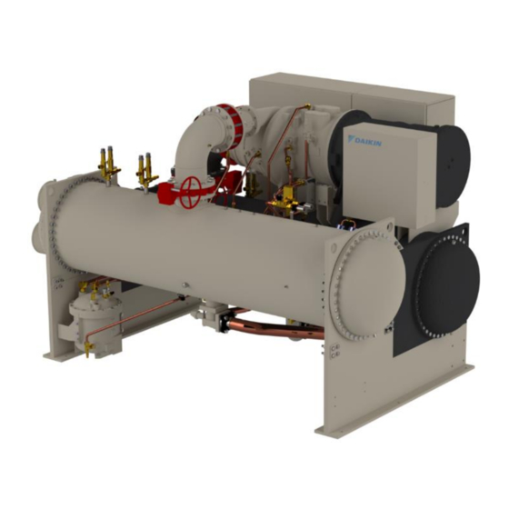
Summary of Contents for Daikin DWSC – Vintage C
- Page 1 Date 06/2021 Supersedes D–EIMWC00803-21_00EN Installation, Operation and Maintenance Manual Installation, Operation and Maintenance Manual D–EIMWC00803-21_01EN DWSC – Vintage C Original Instructions...
-
Page 2: Table Of Contents
CONTENTS INTRODUCTION ..............................10 Precautions against residual risks ........................11 Description ................................12 RECEIVING THE UNIT ............................13 OPERATING LIMITS ............................14 Storing Storage ..............................14 Operation ................................14 MECHANICAL INSTALLATION .......................... 15 Safety ..................................15 Positioning and assembly ............................. 15 System water volume ............................ - Page 3 MAINTENANCE SCHEDULE ..........................38 SERVICE PROGRAMS AND WARRANTY STATEMENT .................. 40 PERIODIC CHECKS AND COMMISSIONING OF PRESSURE EQUIPMENT........... 40 DISPOSAL................................40 IMPORTANT INFORMATION REGARDING THE REFRIGERANT USED ............41 13.1 Factory and Field charged units instructions ....................41 ANNEX A: VARIABLE FREQUENCY DRIVE ..................... 42 14.1 Acceptance of the Product ..........................
- Page 4 Table 8 - Table 1 of EN60204-1 Point 5.2........................... 26 Table 9 - Approved Polyolester oils for R134a units ......................29 Table 10 - Upper Limit For Wear Metals And Moisture In Polyolester Oils In Daikin Centrifugal Chillers ......34 D–EIMWC00803-21_01EN - 4/57...
- Page 5 Fig. 1 - Typical refrigerant circuit Water inlet and outlet are indicative. Please refer to the machine dimensional diagrams for exact water connections D–EIMWC00803-21_01EN - 5/57...
-
Page 6: Fig. 1 - Typical Oil Circuit
Fig. 1 - Typical oil circuit D–EIMWC00803-21_01EN - 6/57... - Page 7 LEGEND DESCRIPTION CENTRIFUGAL COMPRESSOR EVAPORATOR CONDENSER CHECK VALVE SHUT-OFF VALVE* SIGHT GLASS ELECTRONIC EXPANSION VALVE PLUGGED FITTING SOLENOID VALVE FILTER DRYING FILTER #1 DRYING FILTER #2 MOTOR ACUATED VALVE PRESSURE RELIEF VALVE Pset= 13,7 (10,5) bar PRESSURE RELIEF VALVE Pset=13,7 bar OIL HEAT EXCHANGER OIL PUMP WATER VALVE...
-
Page 8: Fig. 2 - Description Of The Labels Applied To The Electrical Panel
Fig. 2 - Description of the labels applied to the electrical panel 1) Electrical hazard symbol 4) Control panel code 2) Non flammable gas symbol 5) Unit nameplate data 3) Gas type 6) Unit characteristics technical Fig. 3 - - Description of the labels applied to the Motor Terminal Box 1) Terminal box fixing 3) Electrical hazard symbol 2) Manufacturer’s logo... -
Page 9: Fig. 4 - Label On Compressor
Fig. 4 - Label on compressor DEVICE UNDER PRESSURE RELEASE PRESSURE IN ALL COMPRESSOR SECTIONS BEFORE SERVICING For more detail see par.13.2.5 D–EIMWC00803-21_01EN - 9/57... -
Page 10: Introduction
All appropriate Personal Protective Equipment (“PPE”) must be used, and a Job Hazard Analysis (“JHA”) must be completed, before beginning any work on the unit. Technicians performing this work must be properly trained on Daikin DWSC Centrifugal equipment. Important Note: In case of any procedure requires accessing the refrigerant circuit of these units, remember that refrigerant is under pressure and oils are contained in these circuits. -
Page 11: Precautions Against Residual Risks
If refrigerant charge of the unit is more than 500 kg it is necessary to install gas sensor on water circuit to catch an eventual gas leakage. Verify that the unit has not zero pressure in the refrigerant circuit before charging water into the heat exchangers. -
Page 12: Description
Description Daikin Centrifugal Water Chillers are complete, self-contained, automatically controlled fluid chilling units. Each unit is completely assembled and factory tested before shipment. Models DWSC are cooling-only. In the DWSC, each unit has one compressor connected to a condenser and evaporator. Information in this manual referring to all DWSC units except where specifically noted. -
Page 13: Receiving The Unit
Extreme care must be used when rigging the equipment to prevent damage to the control panels or refrigerant piping. See the certified dimension drawings included in the job submittal for the center of gravity of the unit. Consult the local Daikin sales office for assistance if the drawings are not available. -
Page 14: Operating Limits
OPERATING LIMITS Storing Storage Environmental conditions must be within the following limits: Equipment room temperature, standby • Water in vessels and oil cooler: 32F to 122F (0C to 50C) • Without water in vessels and oil cooler: 0F to 122F (-18C to 50C) •... -
Page 15: Mechanical Installation
MECHANICAL INSTALLATION Safety The machine must be firmly secured to the ground. It is essential to observe the following instructions: - The machine must be raised only by the lifting points. Only these points can support the whole weight of the unit. - Do not allow unauthorised and/or unqualified personnel to access the machine. -
Page 16: Condensation Control With Well Water
Fig. 6 - Condeser control scheme with cooling tower 1 Cooling tower 2 Condenser Condensation control with well water If ground water is used to cool the condenser, install a normally regulating control valve, direct drive, at condenser outlet. This regulating valve must ensure an adequate condensing pressure in the case where the water temperature entering the condenser is less than 20 °C. -
Page 17: Water Piping
They also serve to shut down the unit in the event that water flow is interrupted to guard against evaporator freeze-up or excessive discharge pressure. Thermal dispersion flow switches and differential pressure switches are available from Daikin as a factory-mounted option. It is mounted in an evaporator and condenser water nozzle and factory wired. -
Page 18: Cooling Towers
Table 1 - Flow switch rates Pipe Size inch 1 1/4 1 1/2 2 1/2 (NOTE!) 32 (2) 38 (2) 63 (3) 102 (4) 127 (4) 153 (4) 204 (5) Min. Flow 13.7 18.0 27.5 65.0 125.0 190.0 205.0 Adjst. 14.8 28.4 43.2... -
Page 19: Field Insulation Guide
Field Insulation Guide D–EIMWC00803-21_01EN - 19/57... - Page 20 Compressor feet D–EIMWC00803-21_01EN - 20/57...
-
Page 21: Physical Data And Weights
4.9.3 Pumpdown To facilitate compressor service, all Daikin centrifugal chillers are designed to permit pumpdown and isolation of the entire refrigerant charge in the unit’s condenser. Dual compressor units and single compressor units equipped with the optional suction shutoff valve can also be pumped down into the evaporator. -
Page 22: Compressor
6000 (2700) 4.10 Oil Coolers Daikin centrifugal chillers, sizes 079 through 126, have a factory-mounted, water-cooled oil cooler, temperature-controlled water regulating valve and solenoid valve per compressor. DWSC single compressor cooling water connections are located near the compressor and are shown on the specific u nit certified drawings. -
Page 23: Fig. 9 - Oil Cooler Piping Across Chilled Water Pump
Fig. 9 - Oil Cooler Piping Across Chilled Water Pump PUMP CHILLER OIL COOLER STOP VALUE SOLENOID VALVE STOP VALVE STRAINER MAX. 40 MESH DRAIN VALVE OR PLUG Fig. 10 - Oil Cooler Piping With City Water OIL COOLER SOLENOID VALVE COOLING TOWER STOP... -
Page 24: Oil Heater
4.11 Oil Heater The oil sump is equipped with an immersion heater that is installed in a tube so that it can be removed without disturbing the oil. 4.12 Relief Valves As a safety precaution and to meet code requirements, each chiller is equipped with pressure relief valves located on the condenser, evaporator, and oil sump vessel for the purpose of relieving excessive refrigerant pressure (caused by equipment malfunction, fire, etc.) to the atmosphere. -
Page 25: Electrical Installation
Power wiring to compressors must be in proper phase sequence. Motor rotation is set up for clockwise rotation facing the lead end with phase sequence of 1-2-3. Care must be taken that the proper phase sequence is carried through the starter to compressor. See wiring diagram. The Daikin start-up technician will determine the phase sequence. D–EIMWC00803-21_01EN - 25/57... -
Page 26: Control Power Wiring
It is the installing contractor’s responsibility to insulate the compressor motor terminals when the unit voltage is 600 volts or greater. This is to be done after the Daikin start-up technician has checked for proper phase sequence and motor rotation. -
Page 27: Phase Unbalance
Phase unbalance In a three-phase system, the excessive imbalance between the phases is the cause of the engine overheating. The maximum permitted voltage unbalance is 3%, calculated as follows: ( ���� − ���� ) ∗ 100 ������������������ % = ���� where: = phase with greater unbalance = average of the tensions... -
Page 28: Prestart System Checklist
Thermometer wells, thermometers, gauges, control wells, controls, etc., installed ❑ ❑ ❑ Minimum system load of 80% of machine capacity available for testing and adjusting controls This checklist must be completed and sent to the local Daikin service location two weeks prior to start-up. D–EIMWC00803-21_01EN - 28/57... -
Page 29: Operation
This Daikin unit represents a substantial investment and deserves the attention and care to keep this equipment in good working order. If the operator observes abnormal or unusual operating conditions, calling Daikin technical service is recommended. -
Page 30: Hot Gas Bypass
When the ambient wet bulb temperature is lower than design, the entering condenser water temperature can be allowed to fall, improving chiller performance. Daikin chillers will start with entering condenser water temperature as low as 55F (42.8C) providing the chilled water temperature is below the condenser water temperature. -
Page 31: Maintenance
MAINTENANCE Pressure/Temperature Chart HFC-R134a Temperature Pressure Chart °F PSIG °F PSIG °F PSIG °F PSIG 41.1 97.0 187.3 10.8 43.2 100.6 192.9 12.0 45.4 104.3 198.7 13.2 47.7 108.1 204.5 14.4 50.0 112.0 210.5 15.7 52.4 115.9 216.6 17.1 54.9 120.0 222.8 18.4... -
Page 32: Routine Maintenance
An annual oil check by a qualified laboratory is essential for maintaining a high level of maintenance. It is useful to have an oil analysis at initial startup to provide a benchmark from which to compare future tests. The local Daikin service office can recommend suitable facilities for performing these tests. - Page 33 The source of tin may be from bearings. Zinc There is no zinc used in the bearings on Daikin chillers. The source, if any may be from additives in some mineral oils. Lead The source of lead in Daikin centrifugal chillers is the thread sealant compounds used during chiller assembly. The presence of lead in the lubricating oil in Daikin chillers does not indicate bearing wear.
-
Page 34: Changing Oil Filters
Changing Oil Filters Daikin chillers are at positive pressure at all times and do not leak contaminated moist air into the refrigerant circuit, th ereby eliminating the need for annual oil changes. An annual laboratory oil check is recommended to check overall compressor condition. -
Page 35: Compressor Maintenance
The centrifugal compressor must rotate in the direction indicated by the arrow on the rear motor cover plate, near the rotation sight glass. If the operator has any reason to suspect that the power system connections have been altered, (phases reversed) the compressor must be jogged to check rotation. For assistance, call the local Daikin service location. 8.2.5... -
Page 36: Cleaning And Preserving
The use of untreated water can result in corrosion, erosion, sliming, scaling or algae formation. It is recommended that the service of a reliable water treatment company be used. Daikin assumes no responsibility for the results of untreated or improperly treated water. -
Page 37: Pressure Testing
pump the system down, close all liquid line valves. With all liquid line valves closed and water flowing, start the compressor. Set the MicroTech control to the manual load. The vanes must be open while pumping down to avoid a surge or other damaging condition. -
Page 38: Maintenance Schedule
MAINTENANCE SCHEDULE Maintenance Check List Item I. Unit • Operational Log • Analyze Operational Log • Refrigerant Leak Test Chiller • Test Relief Valves or Replace II. Compressor • Vibration Test Compressor A. Motor • Meg. Windings (Note 1) • Ampere Balance (within 10% at RLA) •... - Page 39 4. Oil filter change and compressor teardown and inspection should be done based on the results of the annual oil test performed by a company specializing in this type of test. Consult Daikin Factory Service for recommendations. D–EIMWC00803-21_01EN - 39/57...
-
Page 40: Service Programs And Warranty Statement
Daikin offers a variety of maintenance services through the local Daikin service office, its worldwide service organization, and can tailor these services to suit the needs of the building owner. Most popular among these services is the Daikin Comprehensive Maintenance Contract. For further information concerning the many s ervices available, contact your local Daikin service office. -
Page 41: Important Information Regarding The Refrigerant Used
13 IMPORTANT INFORMATION REGARDING THE REFRIGERANT USED This product contains fluorinated greenhouse gases. Do not vent gases into the atmosphere. Refrigerant type: R134a / R513A / R1234ze value: 1430 / 631 / 7 GWP = global warming potential The refrigerant quantity necessary for standard operation is indicated on the unit name plate. Periodic inspections for refrigerant leaks may be required depending on European or local legislation. -
Page 42: Annex A: Variable Frequency Drive
14 ANNEX A: VARIABLE FREQUENCY DRIVE DWSC and DWDC chillers can be equipped with a variable frequency drive (VFD). A VFD modulates the compressor speed in response to load and evaporator and condenser pressures, as sensed by the compressor controller. Due to the outstanding part load efficiency, and despite the minor power penalty attributed to the VFD, the chiller can achieve outstanding overall efficiency. -
Page 43: Vfds And Distortion
14.4 Vfds And Distortion 14.4.1 VFD Line Harmonics VFDs have many benefits, but care must be taken when applying VFDs due to the effect of line harmonics on the building electric system. VFDs cause distortion of the AC line because they are nonlinear loads, that is, they don ’t draw sinusoidal current from the line. -
Page 44: Safety
14.5 SAFETY Installation, start-up and servicing of equipment can be hazardous if certain factors particular to the installation are not considered: operating pressures, presence of electrical components and voltages and the installation site (elevated plinths and built-up up structures). Only properly qualified installation engineers and highly qualified installers and technicians, fully trained for the product, are authorised to install and start-up the equipment safely. -
Page 45: Residual Risks
PE-ADDA400 and PE-ADDA330 products may only be installed in machines designated by the manufacturer Daikin Applied Europe S.p.A. In case of use outside the specifications set out in this manual, the manufacturer’s responsibilities Daikin Applied Europe S.p.A. they come to decay. -
Page 46: Mechanical Installation
Forklift For more safety during transport by forklift, it is recommended ditching the panel to the forklift. Crane or Bridge Crane Fig. 14 - Angle to respect for lifting operation For handling by crane or bridge cranes, before lifting the panel it is necessary to verify the following conditions: •... -
Page 47: Positioning And Assembly
panels and to the base frame. Avoid any part of the machine falling during unloading and/or moving, as this could cause serious damage. All units of the series are supplied with four lifting points. Only use these points for lifting the unit, as shown in Fig. 15. Fig. -
Page 48: General Specifications
14.8 GENERAL SPECIFICATIONS PE-ADDA330, PE-ADDA400 are Variable Frequency Drives (VFDs) specific for Daikin Applied Europe Series Screw Compressors. VFDs are composed of a semi-controlled bridge rectifier, a DC-link, and IGBT power modules. Electronic boards perform power module control and protections. -
Page 49: Individuation Of Parts
14.8.2 Individuation of Parts VFD panel in composed by the elements shown in Fig. below. Fig. 20 - Inverter panel parts (mono) Fig. 21 - Inverter panel parts (dual) Dwg Ref Description Line reactors Capacitors Filters Main switch Fuses D–EIMWC00803-21_01EN - 49/57... -
Page 50: Specification
Fig. 22 - VFD replaceable parts highlighted Dwg Ref Part No. (PE-ADDA200) Part No. (PE-ADDA330) Part No. (PE-ADDA400) Description PE-3ACAP012C PE-3ACAP003C PE-3ACAP014C Capacitor Bank (centrifugal) PE-2PWR001_00EC PE-2PWR001_00FC PE-2PWR001_00CC Power Card PE-2REG002_00AC PE-2REG002_00AC PE-2REG002_00AC Regulation Card PE-2FLT005_01AC PE-2FLT005_01AC PE-2FLT005_01AC Filter Card PE-006FV0400T01 PE-006FV0600L01 PE-006FV0600L01... -
Page 51: Directives And Standards
Max altitude (TN-S, TN-C, TN-CS, TT systems): 2000m with no derating; up to 3000m with 1% rated output current derating every 100m. Max altitude (IT systems): 2000m with no derating; for installation over 2000m please contact your Daikin Applied representative for instructions. -
Page 52: Vfd Terminals
Failure to remove all refrigerant pressure from the whole refrigerant line can result in the pressure ejection of components during disassembly operation and cause personal injury. Any work on refrigerant lines has to be carried out only by trained technicians, please refer to DAIKIN representative. -
Page 53: Maintenance
14.9 Maintenance The maintenance of the product includes the interventions (inspection, verification, control, adjustment and replacement) that are necessary following normal use. For a good maintenance: • Use only original spare parts, tools suitable for the purpose and in good condition. •... -
Page 54: Extraordinary Maintenance
14.9.2 Extraordinary maintenance Any request for extraordinary maintenance must be sent to the manufacturer Daikin Applied Europe S.p.A., who will decide how to proceed. It is recommended not to intervene independently, if the intervention falls outside what is reported in routine maintenance. -
Page 55: Modbus Parameters
14.10.2 Modbus Parameters Main data exchanged through Modbus are: Description Address hex Address scale Type Active current limitation 0x2000 48192 Warning status word 0x2001 48193 STO status word 0x2002 48194 VFD status word 0x2003 48195 Allarmi 0x2004 48196 Regulation Card Temperature 0x2005 48197 Motor Current... - Page 56 Description Address hex Address scale Type VFD Working hours 0x2030 48240 Homopolar motor current 0x2031 48241 Iu true rms 0x2032 48242 Iv true rms 0x2033 48243 Iw true rms 0x2034 48244 Fan working hours 0x2035 48245 Capacitor temperature 0x2036 48246 Max DC Bus 100Hz for grid off P126 0x2037...
- Page 57 The present publication is drawn up by of information only and does not constitute an offer binding upon Daikin Applied Europe S.p.A.. Daikin Applied Europe S.p.A. has compiled the content of this publication to the best of its knowledge. No express or implied warranty is given for the completeness, accuracy, reliability or fitness for particular purpose of its content, and the products and services presented therein.
Need help?
Do you have a question about the DWSC – Vintage C and is the answer not in the manual?
Questions and answers