
Related Manuals for Daikin DWSC Vintage C


Summary of Contents for Daikin DWSC Vintage C
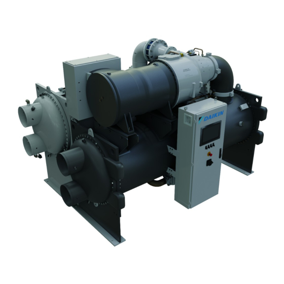
- Page 1 Date 08/2022 D-EOMWC00803-6_00EN Supersedes Operating Manual D-EOMWC00803-26_01EN WATER COOLED CENTRIFUGAL CHILLERS • DWSC Vintage C • DWDC Vintage C...
-
Page 2: Table Of Contents
4.2.10.3 SoftLoad ............................... 17 4.2.10.4 Setpoint Reset ............................. 17 Controller IP setup ............................17 Daikin on Site ............................... 18 Software Options ............................18 4.2.13.1 Changing the Password for buying new Software Options ..............18 4.2.13.2 Inserting the Password in a Spare Controller ..................19 4.2.13.3... - Page 3 Unit Capacity ................................. 23 Unit Mode ................................24 Unit Enable ................................24 Timers ................................... 24 4.10 Alarms ................................... 24 4.11 Commission Unit ..............................25 Alarm Limits ..............................25 Calibrate Sensors ............................25 4.11.2.1 Unit Calibrate Sensors ......................... 25 4.11.2.2 Compressor Calibrate Sensors ......................26 Scheduled Maintenance ..........................
-
Page 4: Safety Considerations
SAFETY CONSIDERATIONS General Installation, start-up and servicing of equipment can be hazardous if certain factors particular to the installation are not considered: operating pressures, presence of electrical components and voltages and the installation site (elevated plinths and built-up up structures). Only properly qualified installation engineers and highly qualified installers and technicians, fully trained for the product, are authorized to install and start-up the equipment safely. -
Page 5: General Description
GENERAL DESCRIPTION Basic Information MicroTech is a system for controlling single or dual-circuit air/water-cooled liquid chillers. MicroTech controls compressor start-up necessary to maintain the desired heat exchanger leaving water temperature. In each unit mode it controls the operation of the condensers to maintain the proper condensation process in each circuit. Safety devices are constantly monitored by MicroTech to ensure their safe operation. -
Page 6: Communication Modules
Figure 1 – Controller Architecture Siemens Part Number Controller/Extension Module Address Usage EWWD/H-VZ/DWSC/DWDC Main Controller POL688.00/MCQ Used on all configurations Unit Extension Module POL985.00/MCQ Used on all configurations Compressor Module 1 POL985.00/MCQ Used on all configurations Compressor Module 2 POL985.00/MCQ Used on some configurations HGBP Module 1 POL94U.00/MCQ... -
Page 7: Using The Controller
USING THE CONTROLLER The control system consists of a unit controller (UC) equipped with a set of extension modules that implement additional features. All boards communicate via an internal peripheral bus with the UC. The UC continuously manages the information received from the various pressure and temperature probes installed on the unit. -
Page 8: Navigating
Alarm status (from any page it links with the page with alarm list, alarm log and alarm snapshot if available). INFO Back to Main Page. Back to the previous level (it can be the Main Page). Used to scroll between the different menu pages, settings and data available on the HMI for the active Wheel password level. -
Page 9: Editing
Editing The Editing Mode is entered by pressing the navigation wheel while the cursor is pointing to a line containing an editable field. Once in the edit mode pressing the wheel again causes the editable field to be highlighted. Turning the wheel clockwise while the editable field is highlighted causes the value to be increased. -
Page 10: Controller Maintenance
Controller maintenance The controller requires to maintain the installed battery. Every two years it’s required to replace the battery. Battery mode l is: BR2032 and it is produced by many different vendors. To replace the battery remove the plastic cover of the controller display using a screw driver as shown in the following pictures: Be careful to avoid damages to the plastic cover. -
Page 11: Embedded Web Interface
Embedded Web Interface The MicroTech controller has an embedded web interface that can be used to monitor the unit when connected to a local network. It is possible to configure the IP addressing of the MicroTech as a fixed IP of DHCP depending on the network configuration. -
Page 12: Menu Structure
Submenu Unit Limiting functions Electrical Data Submenu for electrical data Ctrl IP Setup Submenu for controller IP-address setup Daikin on Site Submenu for connection to Daikin cloud DoS Menu Password Submenu Disable Password for User level D-EOMWC00803-26_01EN - 12/39... -
Page 13: Thermostat Ctrl
Thermostat Ctrl This page resumes all the parameters related to the unit thermostatic control. Setpoint/Sub-Menu Default Range Description 0.0…5.0°C Start Up DT= 2.7°C Offset to start thermostat control 0.0…1.7°C Shut Dn DT= 1.5°C Offset to standby 0.0…1.7°C Stg Up DT= 0.5°C Offset to allow compressor starts 0.0…1.7°C... -
Page 14: Evaporator
Setpoint/Sub-Menu Default Range Description Valve Type NC to Tower NC to tower, NO to Tower Type of bypass valve to tower 15.6…48.9°C Valve/VFD SP= 18.33°C Setpoint for bypass valve and vfd 0…100% Valve Min Pos Valve minimum position 0…100% Valve Max Pos Valve maximum position 0.0…49.0 % Vfd Min Sp... -
Page 15: Options
Setpoint/Sub- Default Range Description Menu Sl1 LWT= Display the Slave1 leaving water temperature Sl2 LWT= Display the Slave2 leaving water temperature Sl3 LWT= Display the Slave3 leaving water temperature Mst EWT= Display the Master entering water temperature Sl1 EWT= Display the Slave1 entering water temperature Sl2 EWT= Display the Slave2 entering water temperature Sl3 EWT=... -
Page 16: Standby Chiller
Setpoint/Sub- Default Range Description Menu Clr Stg Delays This command, visible only with service password, can be Reset used to reset the Stage Up/Dn Timer. 4.2.6.5 Standby Chiller This menu allows to configure the standby chiller Setpoint/Sub- Default Range Description Menu Standby Chiller= No, Auto, Master, Slave 1, Slave... -
Page 17: Power Conservation
Setpoint/Sub- Default Range Description Menu Time 1 0:00..23:59 Define the starting time of 1 time slot Value 1 Off, On Setpoint 1, On Setpoint Define the unit state during 1 time slot Time 2 0:00..23:59 Define the starting time of 2 time slot Value 2 Off, On Setpoint 1, On Setpoint... -
Page 18: Daikin On Site
Check with IT Department on how to set these properties in order to connect the Micro Tech to the local network. Daikin on Site This menu allows to the user to enable the communication with Daikin cloud DoS (Daikin on Site). This option requires that the controller has access to internet. Please contact your service organization for more details. -
Page 19: Inserting The Password In A Spare Controller
If this replacement is scheduled, the customer can ask to Daikin Personnel for a new Password and repeat the steps in chapter 4.2.13.1. If there is no enough time to ask for a Password to Daikin Personnel (ex. an expected failure of the controller), a set of Free Limited Password is provided, in order not to interrupt the machine’s working. -
Page 20: Modbus Mstp Software Option
4.2.13.3 Modbus MSTP Software Option When the software option "Modbus MSTP" is activated and the controller is restarted, the communication protocol settings page can be accessed via the path: Main Menu→Commission Unit→SW Modbus MSTP The values that can be set are the same as those found on the Modbus MSTP option page with the relative driver, and depend on the specific system where the unit is installed. -
Page 21: Bacnet Mstp
4.2.13.4 BACNET MSTP When the software option "BACNet MSTP" is activated and the controller is restarted, the communication protocol settings page can be accessed via the path: Main Menu→Commission Unit→SW BACNet MSTP The values that can be set are the same as those found on the BACNet MSTP option page with the relative driver, and depend on the specific system where the unit is installed. -
Page 22: Bacnet Ip
4.2.13.5 BACNET IP When the software option "BACNet IP" is activated and the controller is restarted, the communication protocol settings page can be accessed via the path: Main Menu→Commission Unit→SW BACNet IP The values that can be set are the same as those found on the BACNet MSTP option page with the relative driver, and depend on the specific system where the unit is installed. -
Page 23: Menu Password
Menu Password It is possible to keep the User level always active to avoid to enter the User password. To do this the Password Disable setpoint shall be set to On. Setpoint/Sub-Menu Default Range Description Pwd Disable Off, On Menu for Circuit #1 Active Setpoint This link jumps to the page “Tmp Setpoint”. -
Page 24: Unit Mode
Unit Mode This item shows the present Operating Mode and jumps to the page for unit mode selection. Setpoint/Sub-Menu Default Description Available Modes= Cool Cool, Available operating modes Cool w/ Glycol, Cool/Ice w/Glycol, Ice w/Glycol, Heat/Cool, Heat/Cool w/Glycol, Heat/Ice w/Glycol, Pursuit, Test Depending on selected mode among availables, the Unit Mode on the main menu will assume the corresponding value... -
Page 25: 4.11 Commission Unit
4.11 Commission Unit Setpoint/Sub-Menu Default Range Description Save Settings Save current settings Software Update Submenu for software updating Alarms Limits Submenu for alarm limits definition Calibrate Sensors Submenus for Unit and Circuit sensor calibration Manual Control Submenus for Unit and Circuit manual control ... -
Page 26: Compressor Calibrate Sensors
4.11.2.2 Compressor Calibrate Sensors This page allows to adjust the sensors and transducers readings. Setpoint/Sub-Menu Default Range Description Suction Temp Suction Temperature current reading (includes the offset) Suction Offset 0.0°C Suction Temperature offset Discharge Temp Discharge Temperature current reading (includes the offset) Discharge Offset 0.0°C Discharge Temperature offset... -
Page 27: Working With This Unit
WORKING WITH THIS UNIT This section contains a guide on how to deal with the everyday usage of the unit. Next sections describe how to perform routine tasks on the unit, such as: • Unit Setup • Unit/Circuit start-up • Alarm handling •... -
Page 28: Temperature Settings
Mode Description Unit Range Pursuit Set in case of double water control cool and contemporary heat. Evaporator leaving water temperature follows the Cool LWT 1 setpoint. Condenser leaving water temperature follows the Heat LWT 1 setpoint. Test Enables the Manual Control of the unit. The manual test feature helps in debugging and checking A/C and W/C the operational status of sensors and actuators. -
Page 29: Pumps
Thermostat Control OFF Thermostat Control ON Thermostat Control OFF AS+SU COOL MODE Capacity load up Capacity Unload AS-SD Thermostat Thermostat Control OFF Thermostat Control ON Control AS+SD Capacity Unload HEAT MODE Capacity load up AS-SU Figure 5 – Thermostat Control Settings 5.1.3.3 Pumps The UC can manages one or two water pumps for both evaporator and condenser. -
Page 30: Current Limit
Capacity Limit Maximum Capacity Parameter Description Unit Capacity Displays current unit capacity Demand Limit En Enables demand limit Demand Limit Displays active demand limit Minimum Capacity Demand Limit [mA] 5.1.4.2 Current Limit Current limit function allows to control unit power consumption taking current drawn below a specific limit. Starting from the Current Limit Setpoint defined through the HMI or BAS communication, user can change the limit. -
Page 31: Soft Load
LWT SP + MR Parameter Default Range 0.0°C 10.0°C Max Reset (MR) 5.0°C 0.0°C 10.0°C 5.0°C Start Reset DT (SRT) Active Setpoint (AS) LWT Target (LWT SP) Cool/Ice LWT LWT SP Evap T SRT 5.1.4.6 Soft Load Soft Loading is a configurable function used to ramp up the unit capacity over a given time period, usually used to influence building electrical demand by gradually loading the unit. -
Page 32: Prepare The Unit To Start
Overall Status Status text Description Noise Reduction Unit is running with the Quiet Mode activated. Active setpoint may differ from what has been set as cooling setpoint. Max Pulldn Unit thermostat control is limiting the unit capacity because the water temperature is dropping at a rate that could exceed the active setpoint. -
Page 33: Figure 6 - Condenser Water Temperatur
Fan Stage Cond VFD Max Speed VFD Min Speed Cond Figure 6 – Condenser Water Temperatur • 1 Vfd by mean of a modulating 0-10V signal generated through a PID controller. The following graph is an example of the modulating signal behavior in case of a PID control supposed to be purely proportional. D-EOMWC00803-26_01EN - 33/39... -
Page 34: Operator Interface Touchscreen-Oits
OPERATOR INTERFACE TOUCHSCREEN-OITS Overview The OITS application is defined to exchange real-time data with the MicroTech controller. Verify that the monitor is connected to the PLC via Ethernet cable so that the PLC data is displayed correctly . It allows the unit's operating parameters to be set and the data to be displayed. At the top of the monitor the Off/On button, the cooling setpoint, the unit mode and the actual capacity are visible. -
Page 35: Set User Level
Set user level In order to unlock customer functionalities, the User must insert the Password through the Set User Level Entry. Homepage The Home page Information Panel contains the main information of the unit such as: Condenser Leaving Water Temperature Condenser Entering Water Temperature Evaporator Leaving Water Temperature Evaporator Entering Water Temperature... -
Page 36: Global Settings
Global settings In the setting menu it is possible to: Select the OITS language (Only English available at the moment) Select the Engineering Units (Imperial, Metric) Calibrate the Touchscreen Select the logging Update the software version when a new release is available. In addition the system device and the USB device (if present) storages are shown. -
Page 37: Tab
Tab pages Each Tab page allows the user to show data from different unit’s component: • Unit • Compressors • Evaporator • Condenser Live trend In this page it is possible to monitor all the datapoints available in the datapoint list. It is possible to track a maximum of 4 datapoints for each graph chart. -
Page 38: Options
OPTIONS Energy Meter including Current Limit (Optional) An energy meter can be optionally installed on the unit. The energy meter is connected through Modbus to the unit controller, which can display all relevant electrical data such as: • Line to Line Voltage (per phase and average) •... - Page 39 Specification are subject to change without prior notice. Refer to the data communicated at the time of the order. Daikin Applied Europe S.p.A. explicitly rejects any liability for any direct or indire ct damage, in the broadest sense, arising from or related to the use and/or interpretation of this publication.
Need help?
Do you have a question about the DWSC Vintage C and is the answer not in the manual?
Questions and answers